How can we help?
Introduction to Through-Hull Deployment Machine
18 January 2023
This article describes the Sonardyne Through-Hull Deployment Machine and the installation procedures.
Description
Our Through-Hull Deployment Machine is described below.
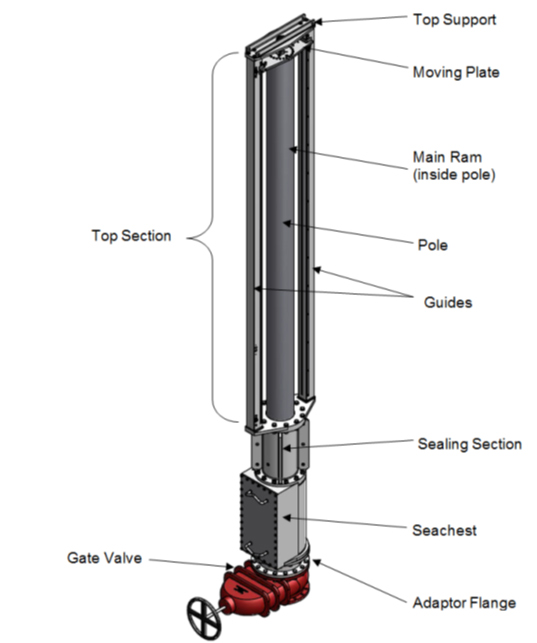
Our standard model typically extends the pole so that the face of an attached Transceiver is about 2‑3 m below the hull.
We can also supply longer versions to accommodate deeper penetrations, or to overcome double-skinned hulls, or shorter ones where installation space is a premium.
These types of machine have been supplied to vessels of all sizes and types all over the world since 1996.
The Deployment Machine sits on a Gate Valve, and with the Gate Valve open, an operator can press a button from one of the available control panels, and the pole will move downwards.
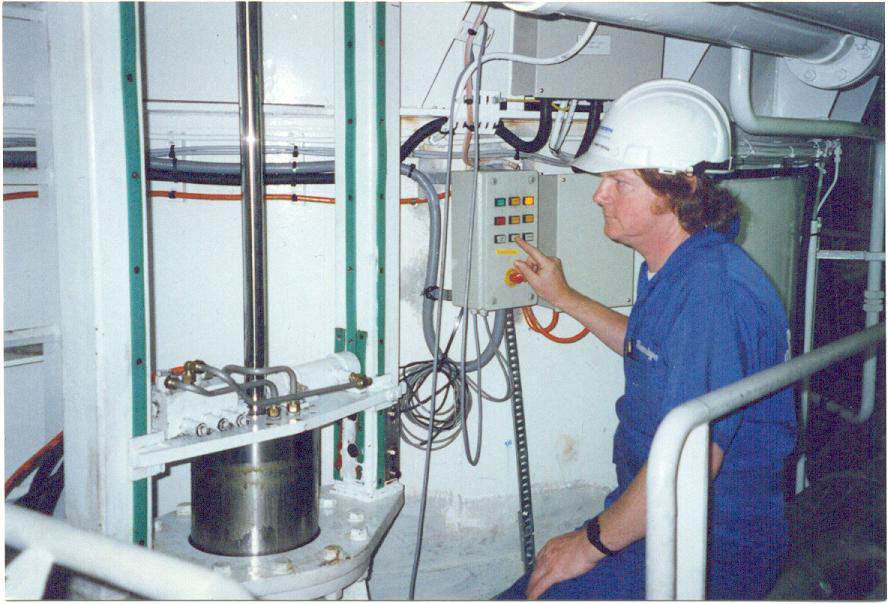
Another button will move the pole up again.
Typically mounted on the end of the pole is our HPT Transceiver or Gyro USBL.
When in dry dock, this is easily serviced by deploying the pole through the hull.
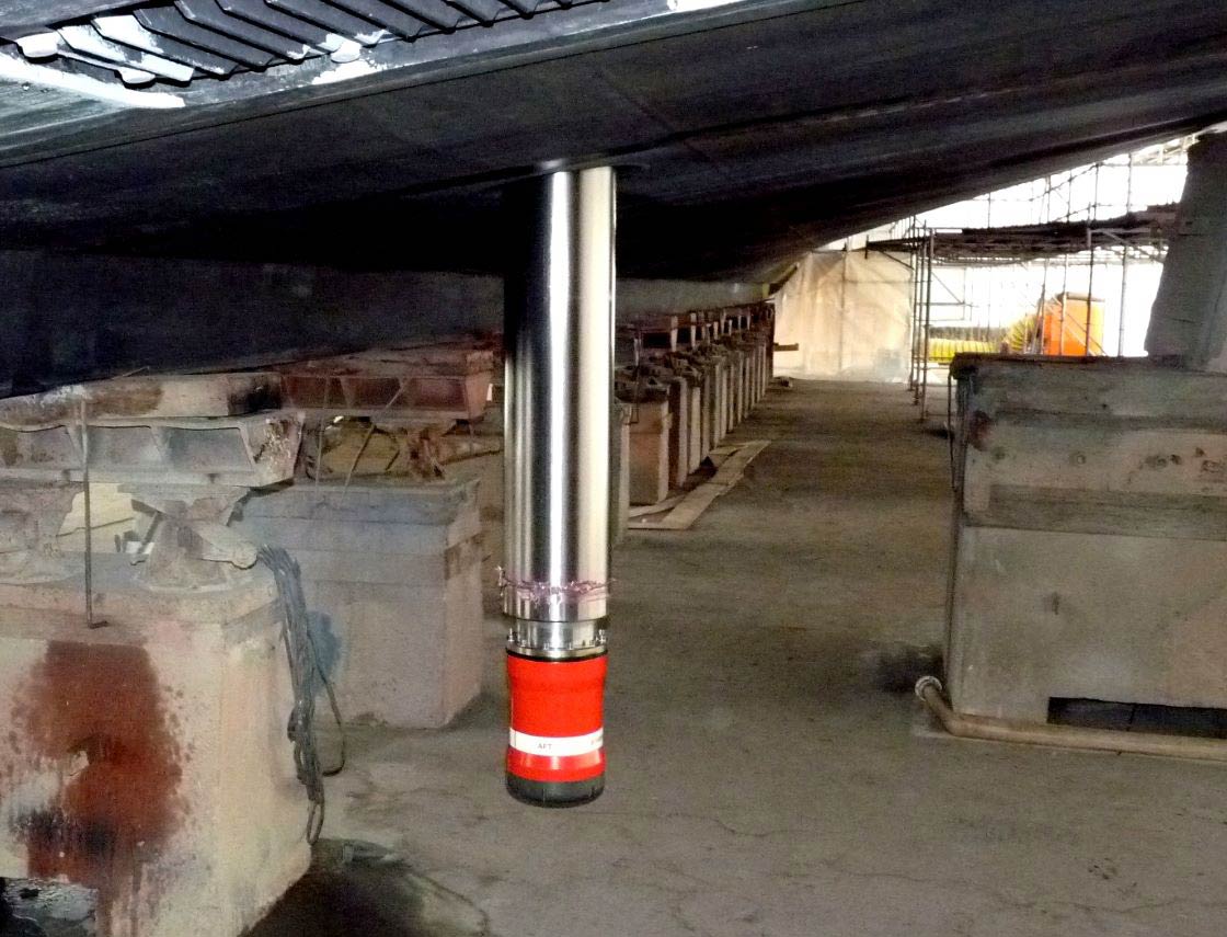
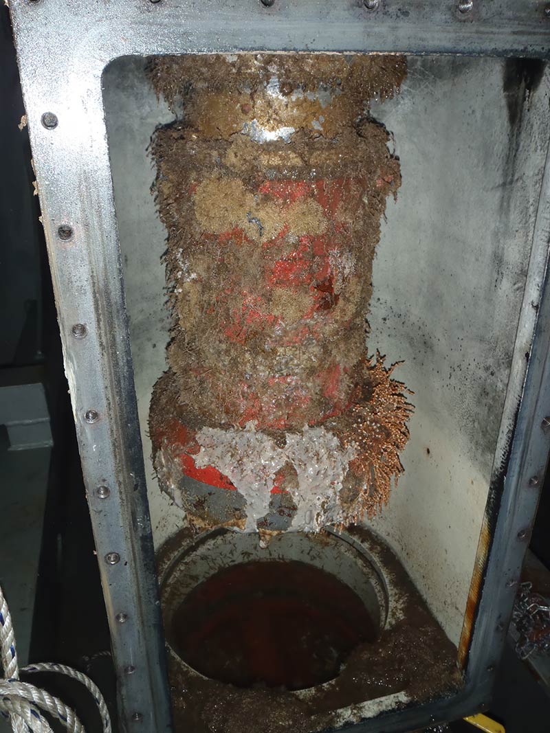
At sea, with the Gate Valve closed, the Sea Chest can be drained, and then opened to gain access to the Transceiver/GyroUSBL.
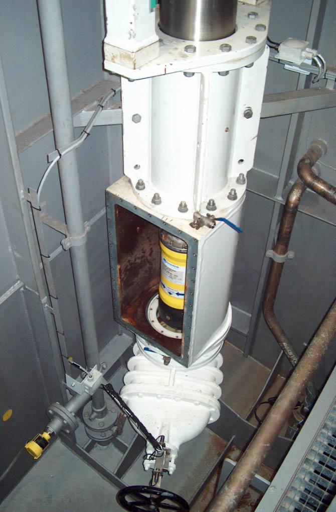
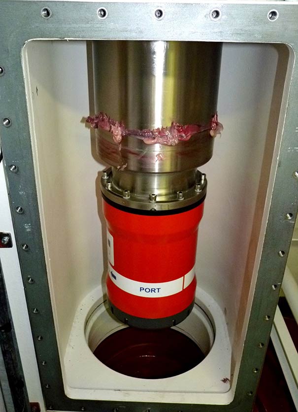
Sometimes it will need cleaning, so it’s a good idea to inspect it now and again.
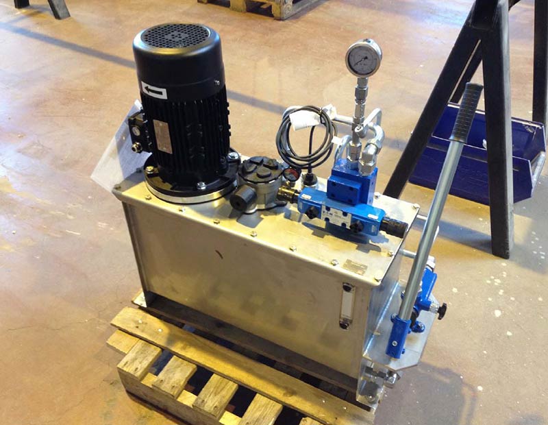
The machine is hydraulically driven from a Hydraulic Power Unit (HPU).
Control Panels
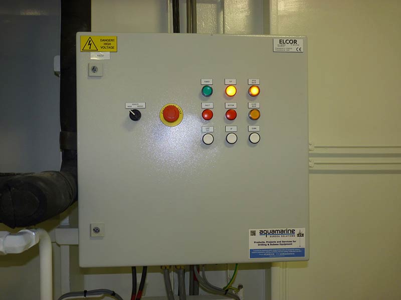
Control panels provide the user-interface, in order to lower and raise the pole, and – if a Hydraulic Actuator is fitted – open and close the Gate Valve.
This is the Main Control Unit.
This is the Local Control Unit, which is intended to be mounted inside the cofferdam, next to the Deployment Machine for commissioning purposes.
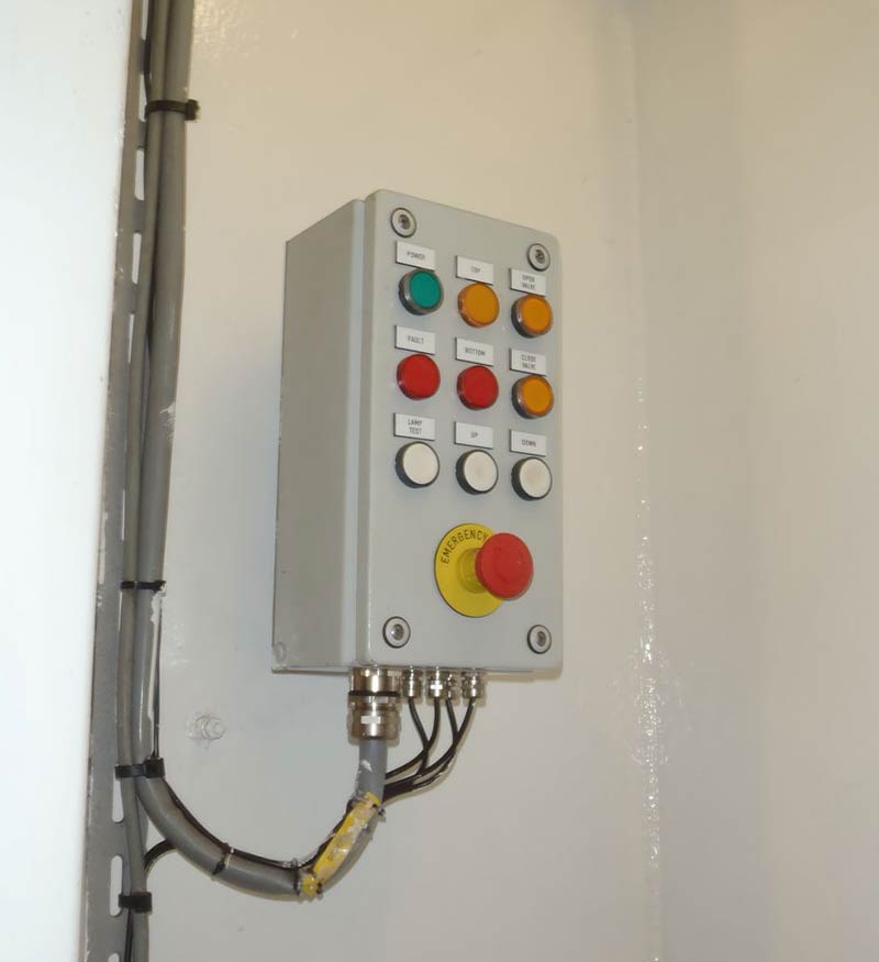
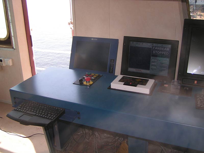
This is the Bridge Panel Assembly, which is often the preferred Bridge control device.
We also provide a Bridge Control Unit (similar to a Local Control Unit) for wall-mounting.
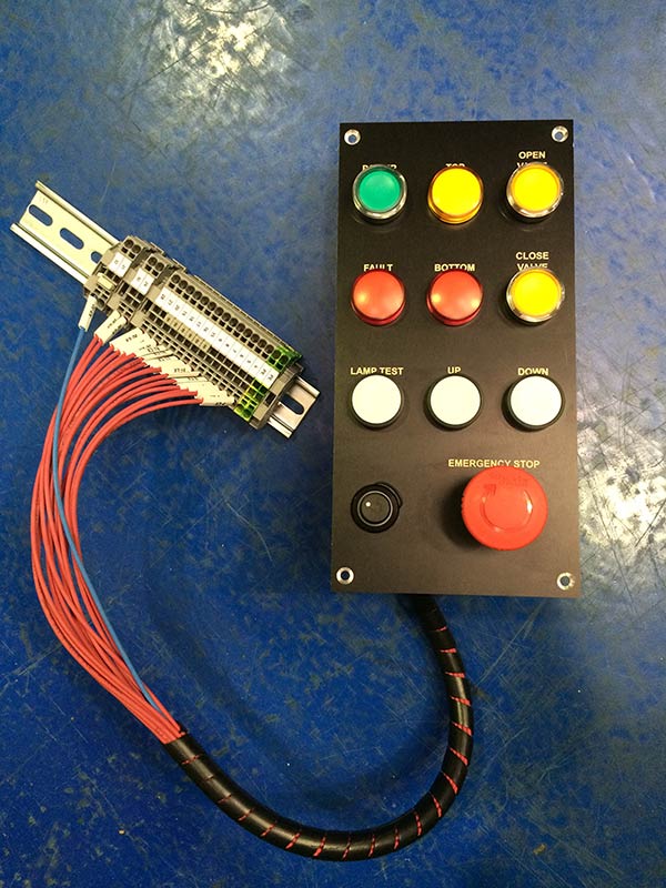
Bridge Panel Assembly
Here’s the Bridge Panel Assembly fitted.
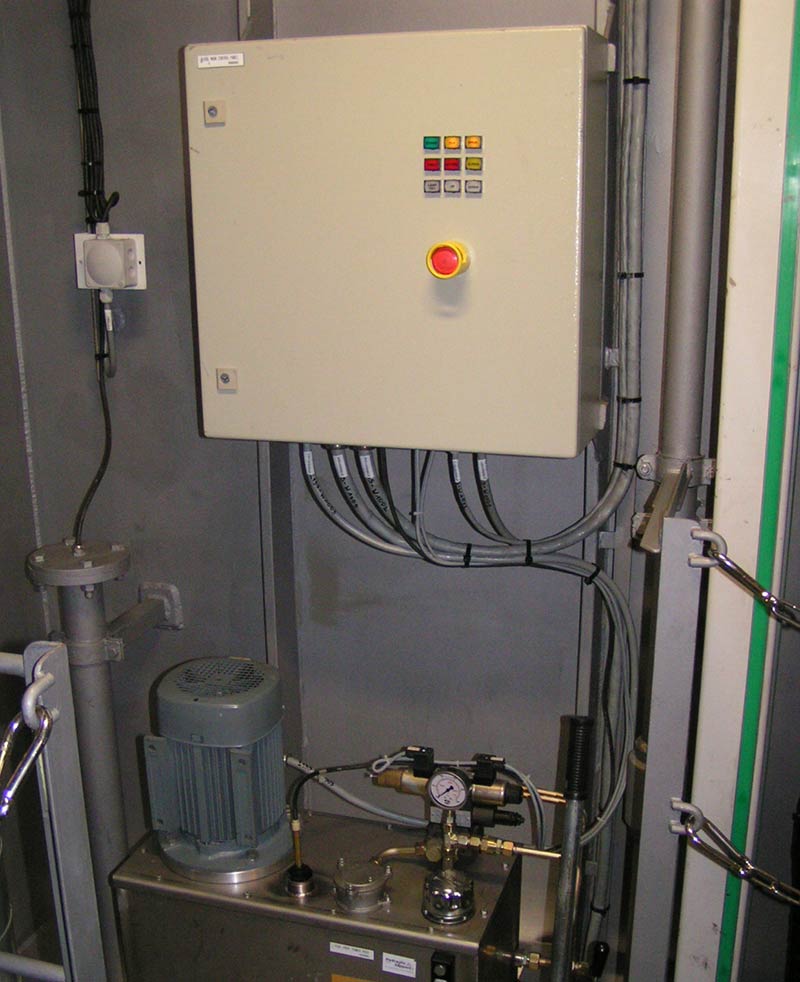
HPU and Main Control Unit
The HPU and Main Control Unit should be mounted close to each other, but outside the cofferdam.
A water-tight cofferdam is the preferred location for the Deployment Machine, so that if it floods, at least only the Local Control Unit will be sacrificed.
The HPU has a hand pump, and in an emergency, and for some commissioning activities, this can be used to manually pump the pole up and down – and if a hydraulic actuator is fitted – pump the Gate Valve open and closed.
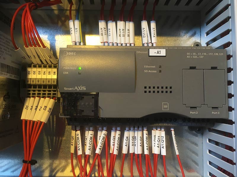
The new IDEC SmartAxis PLC introduced into the new Main Control Cabinet in July 2016, provides an RS485 interface, which can be used to control the Deployment Machine (and Gate Valve Actuator if fitted) via software.
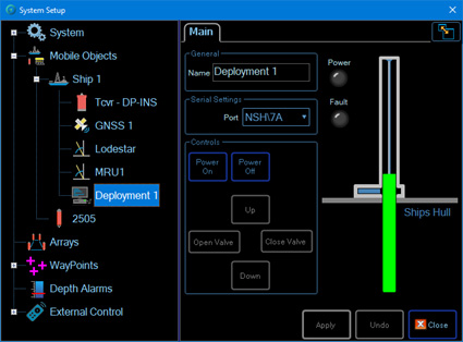
Ranger 2 and Marksman
This is how it looks in Ranger 2 or Marksman.
Installation
Let’s look at a typical installation.
First of all, a suitable hole is cut in the hull of the vessel.
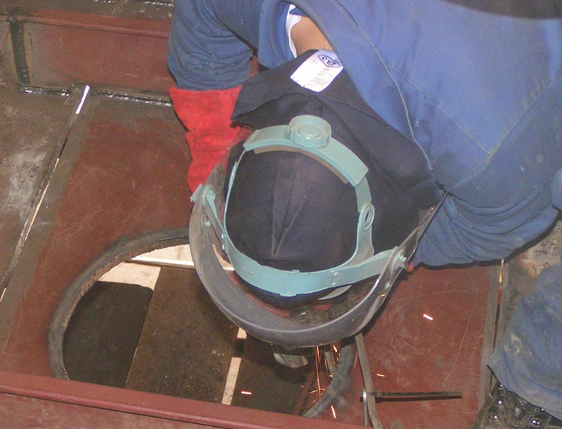

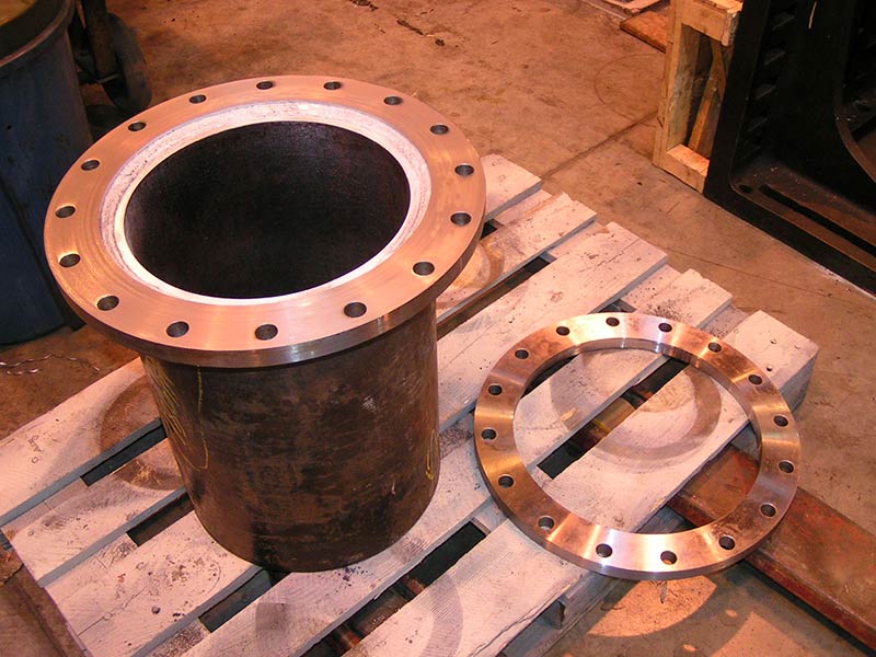
The vessel supplies a through-tube penetrator pipe, which is used to penetrate the vessel hull.
The Weldable Flange (which we supply) is welded to the through-tube penetrator pipe, and the Gate Valve will sit on top of this flange.
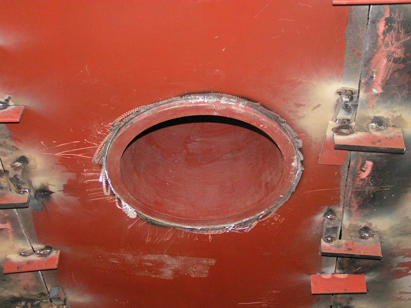
The length of the through-tube penetrator pipe should be kept to a minimum – typically 150-300 mm.
This provides adequate space to install the Gate Valve fixings but does not impact on the overall depth to which the transceiver will be deployed. A reduction in the deployed length could impact on the acoustic performance.
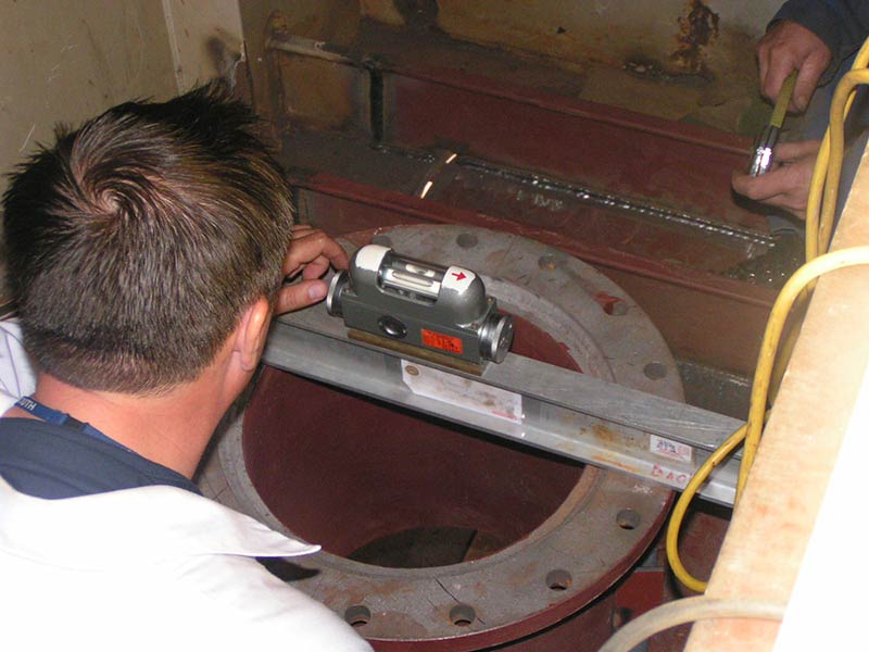
The through-hull pipe must have adequate internal diameter for the required sensor, as shown in the table below.
| Sonardyne Instrument | Unit Diameter (mm) |
| HPT 2000 | 234 |
| HPT 3000 | 234 |
| HPT 5000 | 225 |
| HPT 7000 | 310 |
| Gyro USBL 5000 | 225 |
| Gyro USBL 7000 | 310 |
| Sentinel | 330 |
It is advisable to have rigid straffing stakes around the through-tube penetrator pipe, to ensure a sturdy base for the Gate Valve and Deployment Machine.
This also helps take the strain when the pole is deployed, and can be vital in cases where the pole is accidentally left deployed and the vessel runs aground.
In such cases, a poorly-supported penetrator pipe could rupture before the pole bends, and cause serious flooding to the cofferdam.
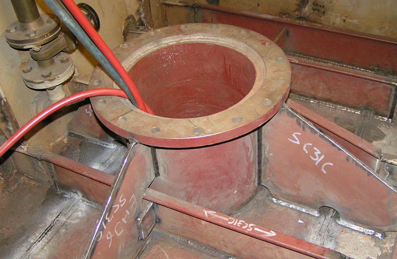
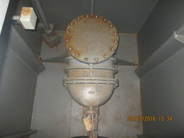
The Gate Valve sits on top of the Weldable Flange and is bolted in position, with a gasket seal between each face.
The picture below shows a DN350 Gate Valve with a Hydraulc Actuator fitted.
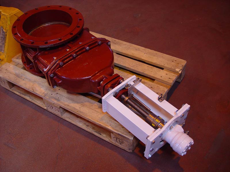
The Hydraulic Actuator is optional. A standard delivery would be with just a wheel to manually open and close the valve, together with gasket, fixings, and open/close proximity sensors.
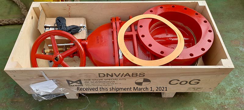
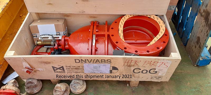
Our standard size is the DN350 Gate Valve (as the name suggests, this has a 350mm internal diameter).
If the Gate Valve is to be installed some time before installation of the Deployment Machine, and the vessel is to be floated out of dry dock, then a blind flange is recommended to guard against leakage through the valve seat seal.
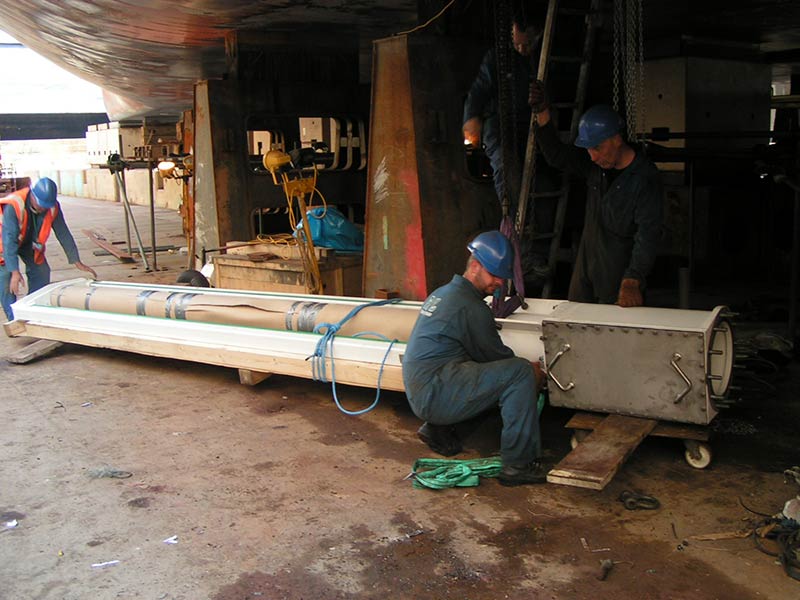
A Deployment Machine being prepared for installation.
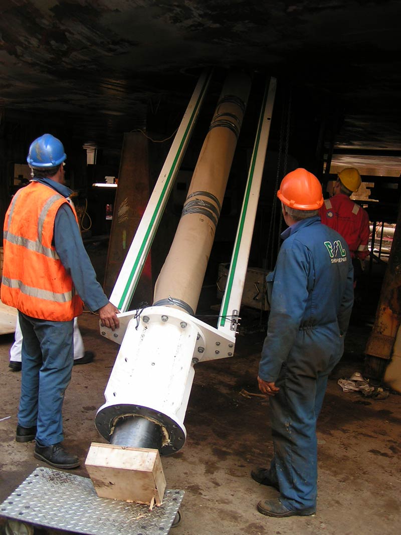

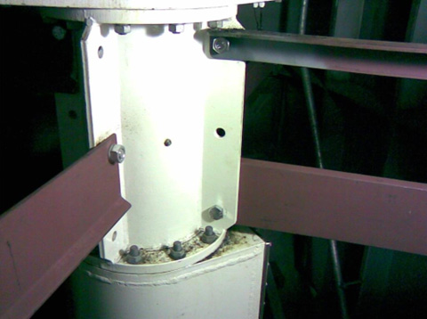
Bracing is fitted to the Bearing & Sealing Section to provide a rigid foundation for the Deployment Machine.
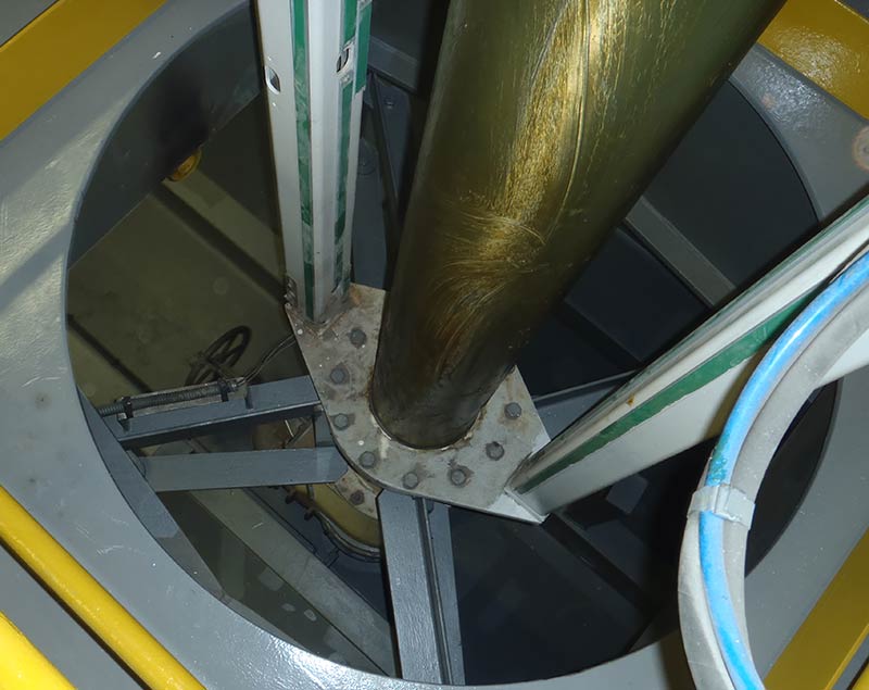
The machine is also supported at the top.
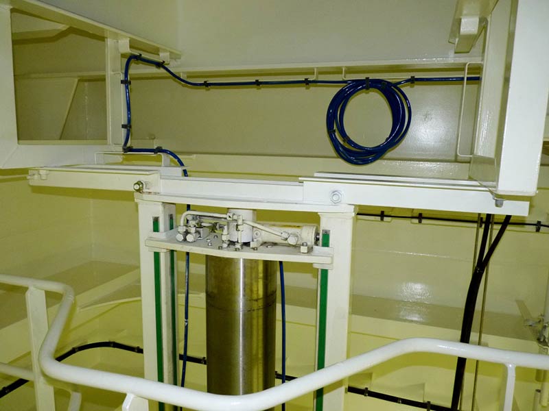
Although not as critical as the Bearing & Sealing Section bracing, it nevertheless, assists with the reduction of vibration.
Hydraulic hoses run from the HPU: one to provide hydraulic pressure to drive the pole down; another hose to drive the pole up.
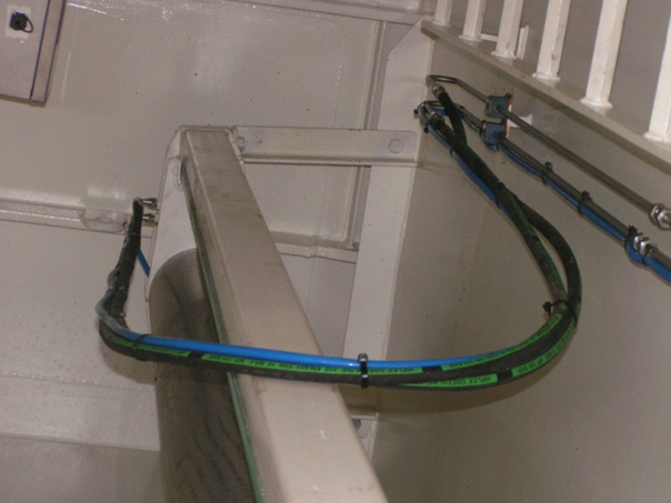
A further two hoses are required to drive the Gate Valve open and closed if a Hydraulic Actuator is fitted.
The pole automatically stops when it triggers a proximity sensor at the top of the machine.
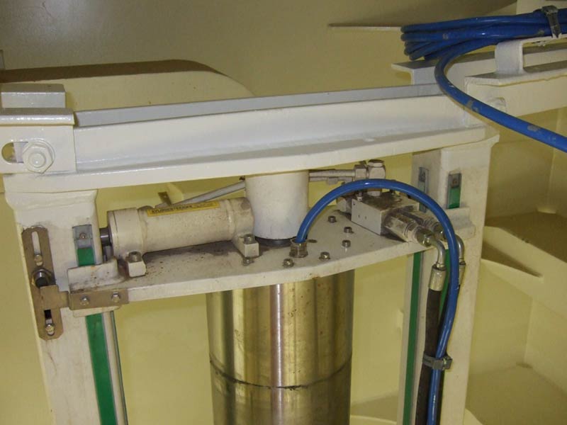
It also automatically stops when it triggers another at the bottom of the machine.
Gate Valves use the same type of proximity sensor to determine their Open and Closed state.
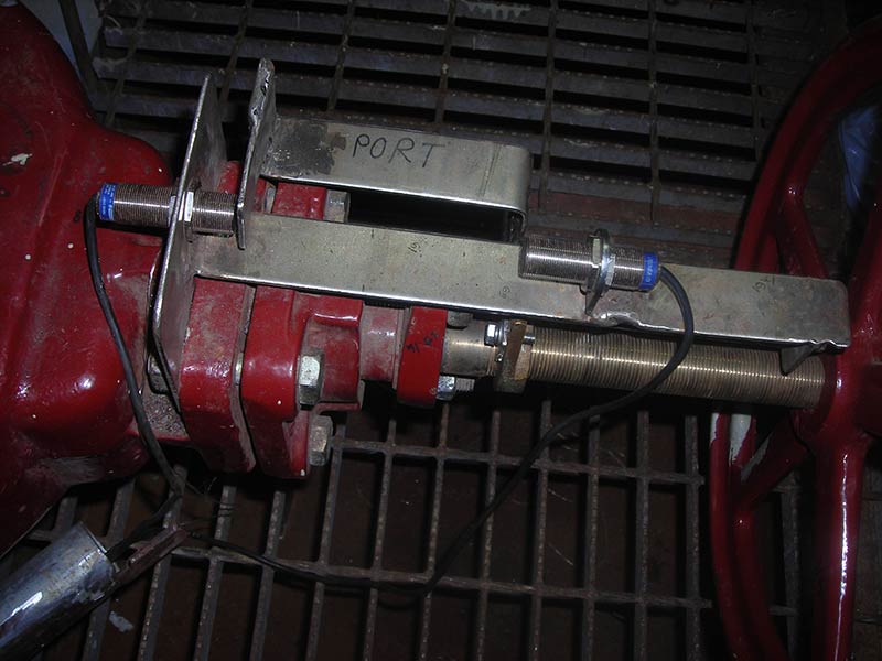
The Deployment pole is held rigid at any position along its travel – accomplished by its counterbalance (overcentre) valve.
However, at its fully-up and fully-down position, a hydraulic pin pushes into a securing hole, to provide an extra element of support.

For more detailed information, see the Deployment Machine support pages.
Looking for more content?
Find more product support in our Knowledgebase
Haven't found what you're looking for?
Then speak to one of our team for expert help
