Long endurance monitoring of tectonic motion
Subduction zones are tectonic plate collision boundaries where typically higher density oceanic crust is being pushed under continental crust. This is one of the most important processes in the evolution of the Earth’s morphology.
The challenge
Subduction zones comprise extremely large thrust faults, known as megathrusts, and are the source of the world’s most dangerous volcanoes and earthquakes. In between larger earthquakes, megathrusts comprise complex heterogeneous distributions of locking and therefore strain accumulation.
On land, GPS and laser observations enable precise geodetic measurements. Until recently, the inability to undertake cost-effective complementary observations subsea in the outermost subduction zone offshore, has been a critical flaw. This is where much of the elastic strain build-up and release occurs. Improving scientific understanding of the seafloor movement in these regions is an important basis for future seismic hazard assessment.
The solution
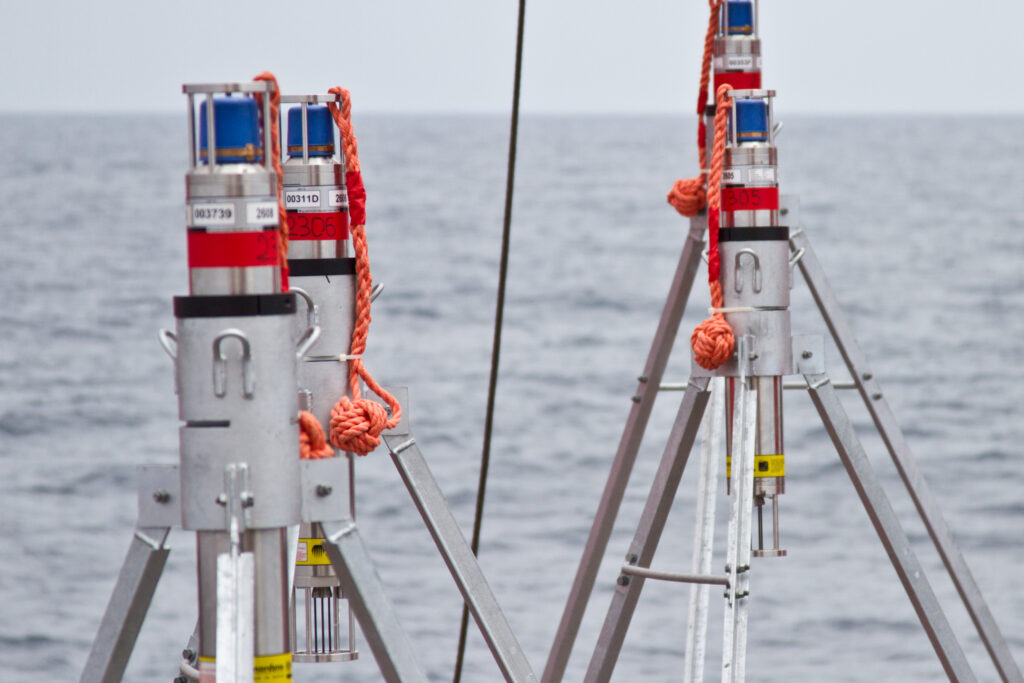
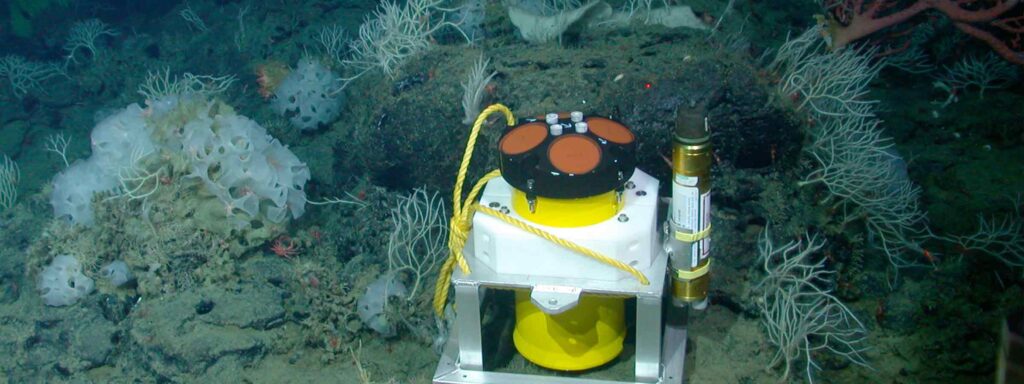
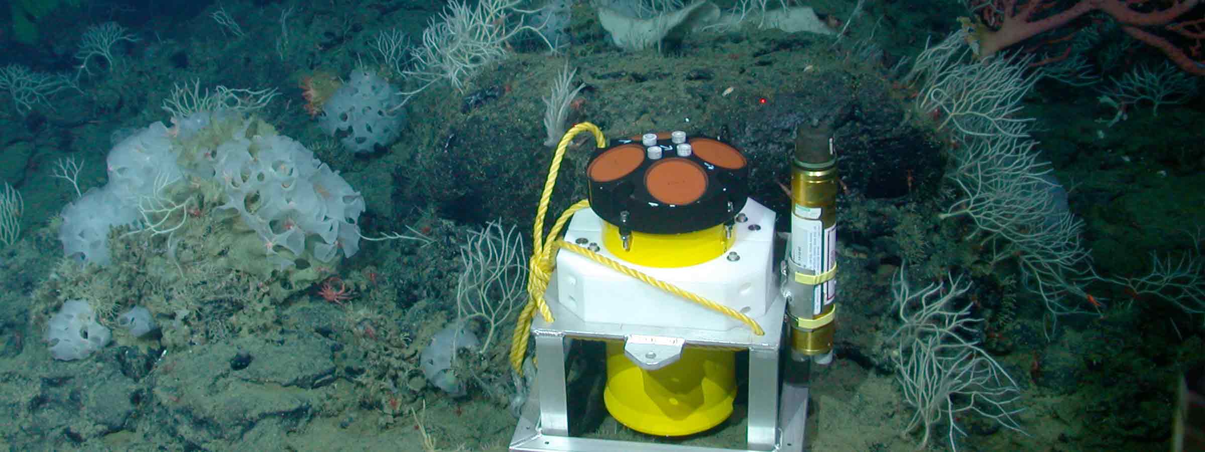
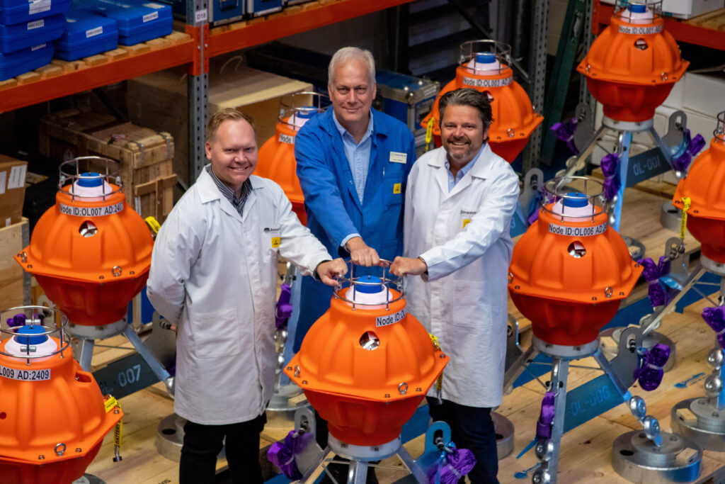
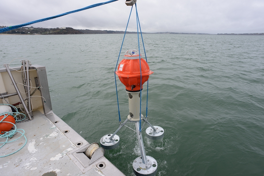
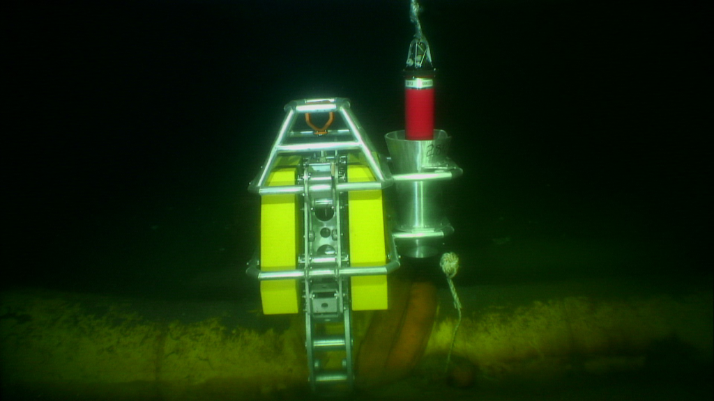
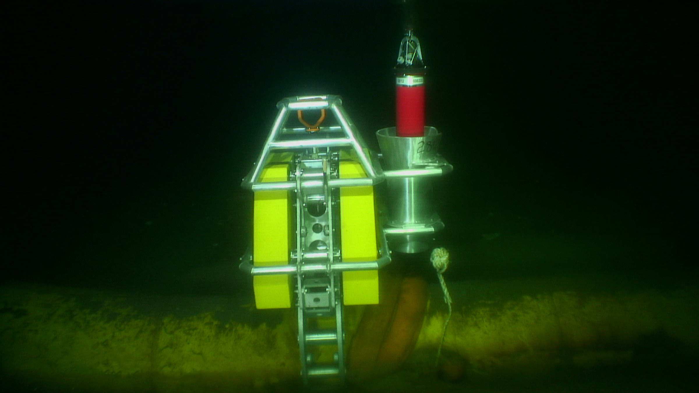
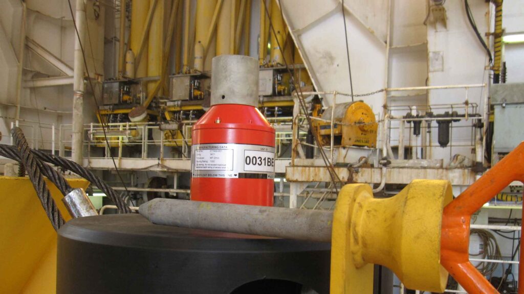
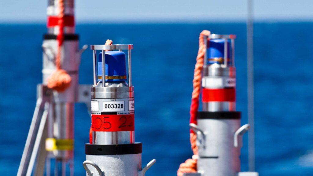
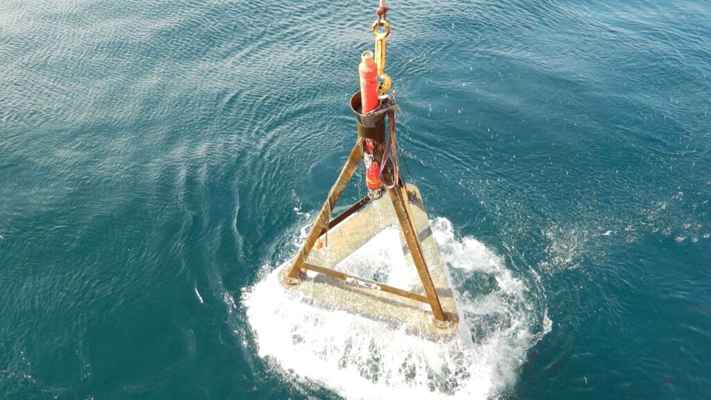
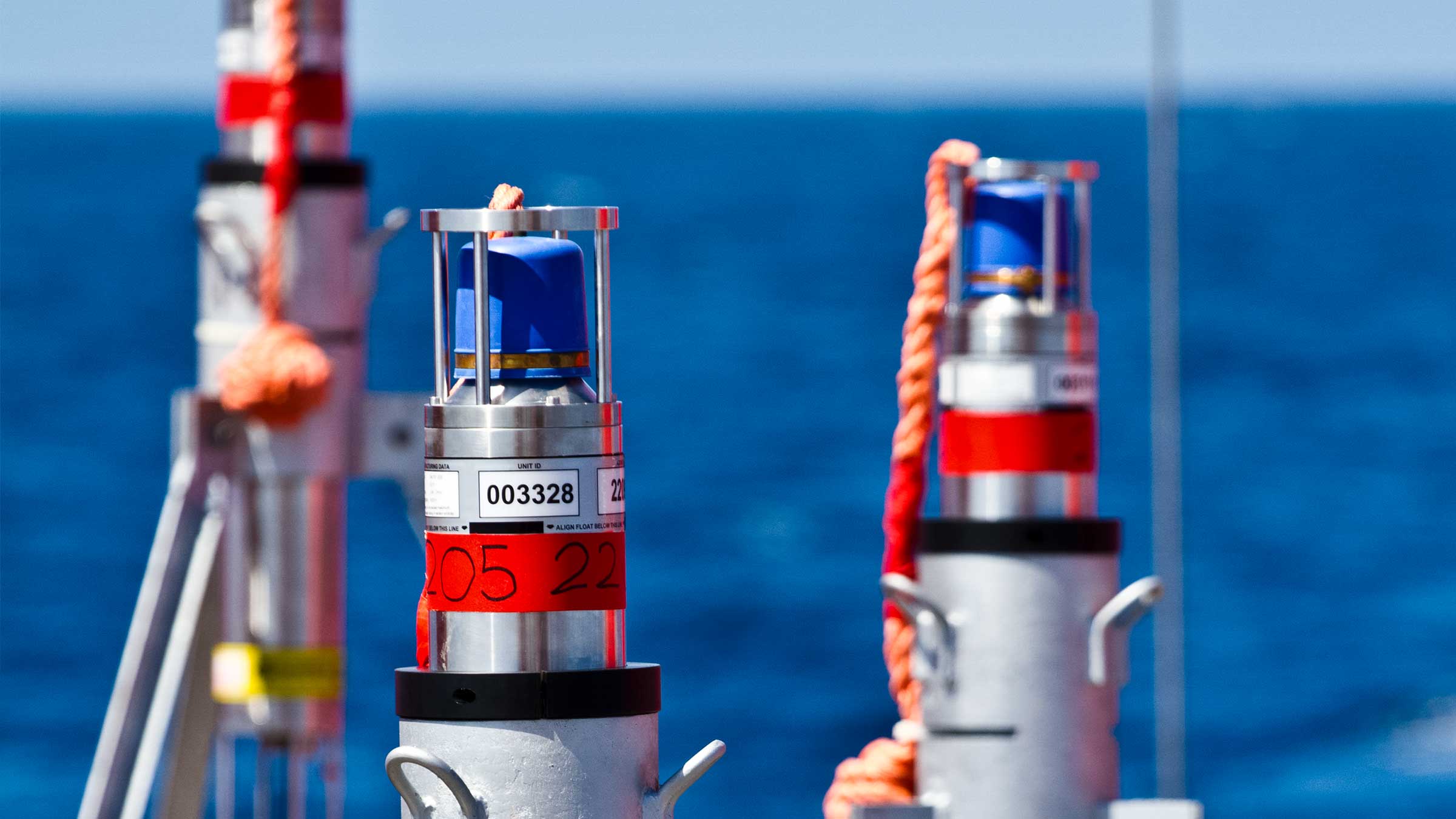
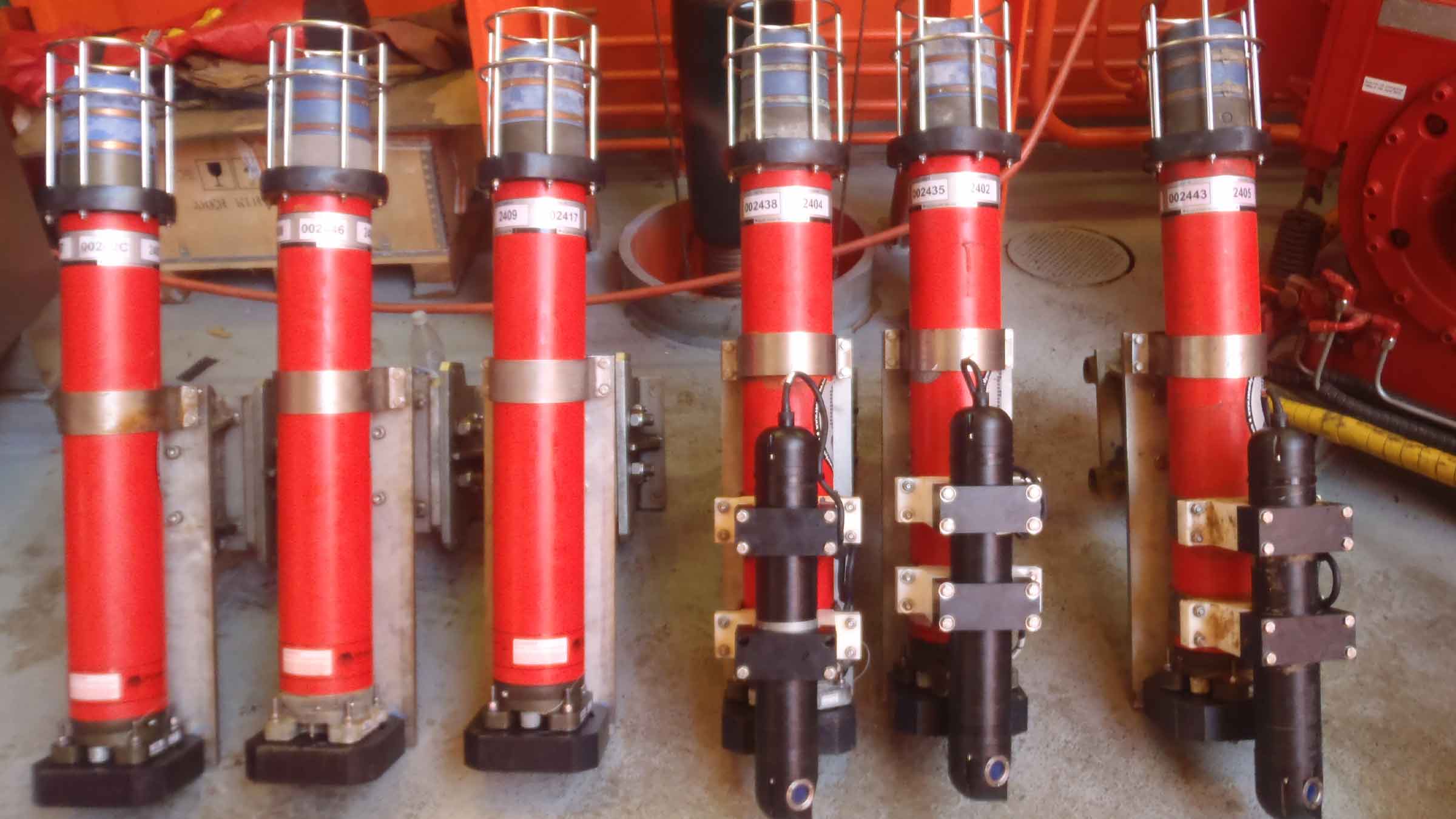
In response to this challenge, Sonardyne has worked with a number of research institutes, including GEOMAR, to supply networks of Autonomous Monitoring Transponders (AMTs ) – seabed instruments that are capable of taking hundreds of thousands of stable, highly precise geodetic observations, safely log the data and on command, wirelessly transmit it up to the surface.
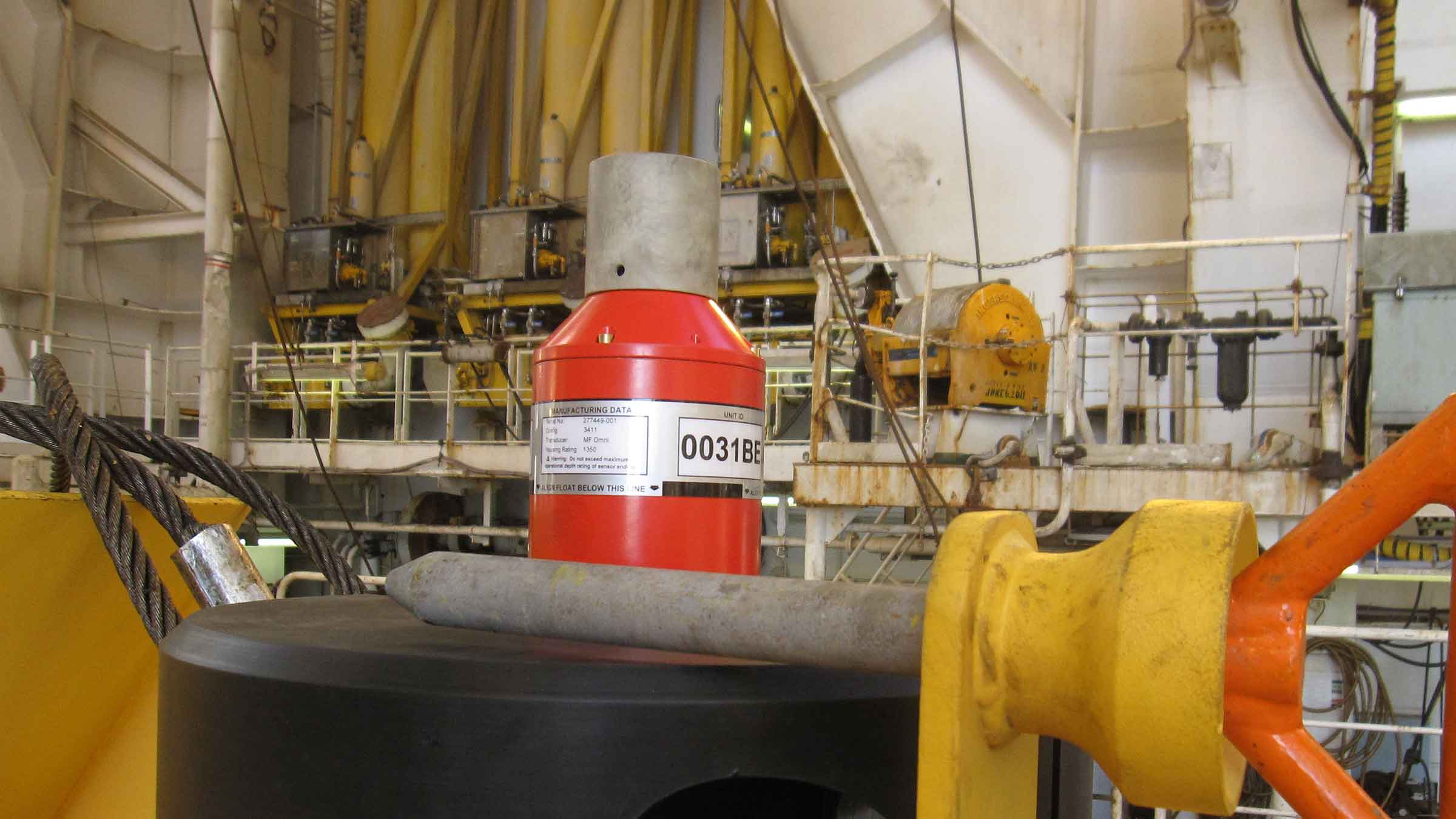
Originally developed for the offshore industry to precisely measure vertical and horizontal seabed displacements caused by reservoir depletion, AMT is a long-life (up to five years depending configuration), deep-rated acoustic instrument fitted with high resolution pressure, sound velocity and temperature sensors. All of this is built around our 6G hardware platform and Wideband 2 digital signal technology.
AMTs run a fully automated logging regime gathering acoustic travel time (range) between neighbouring units, pressure, sound velocity, temperature and tilt data at intervals defined by the user. A passing AUV, vessel of opportunity, gateway buoy or unmanned surface platform can harvest data on demand and at any point, the user may amend the logging regime of any or all of the AMTs, using the bi-directional communications link.
GEOMAR have now deployed three AMT seabed arrays in Chilean seas. The largest array is the Geodetic Earthquake Observatory on the SEAfloor (GeoSEA) project, offshore northern Chile on the Nazca-South American plate boundary.
The last rupture resulting in a major earthquake at the array location was in 1877. This was identified as a seismic gap prior to the 2014 Iquique/ Pisagua 8.1 magnitude earthquake.
Nevertheless, the southern portion of the segment remains unbroken by recent earthquake activity and so, with the two plates converging at a rate of around 65 millimetres per year, new tension is being continuously built up. ‘Therefore the region is a focus site for seismologists to understand strain build-up prior to an earthquake,” says Professor Kopp
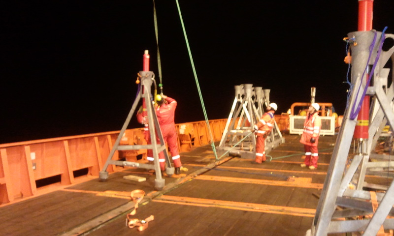
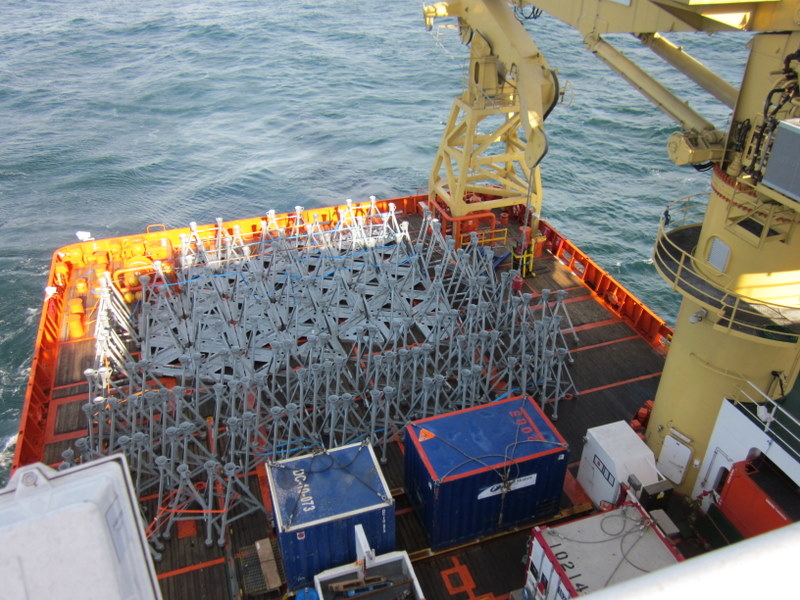
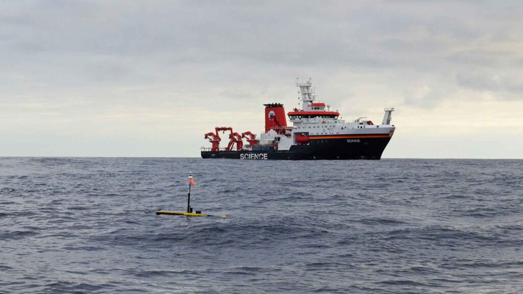
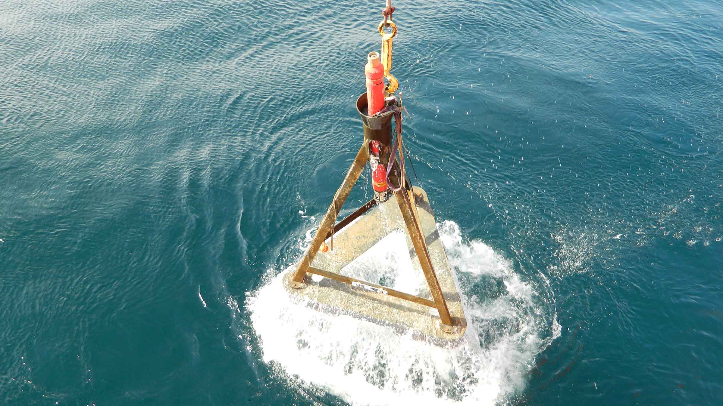
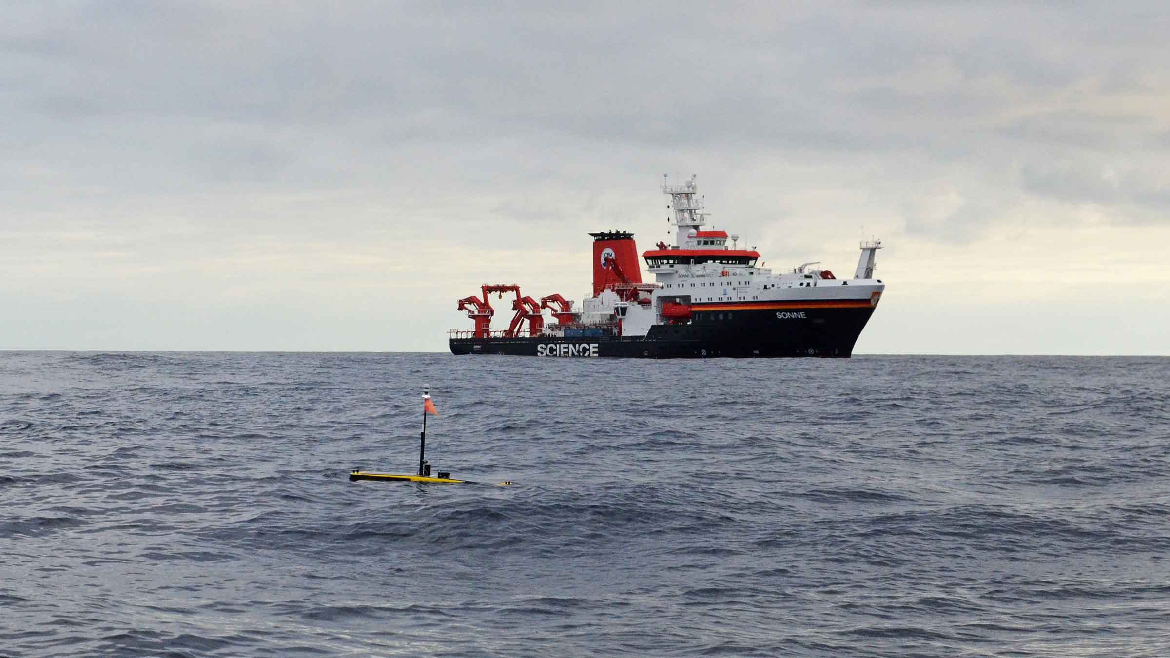
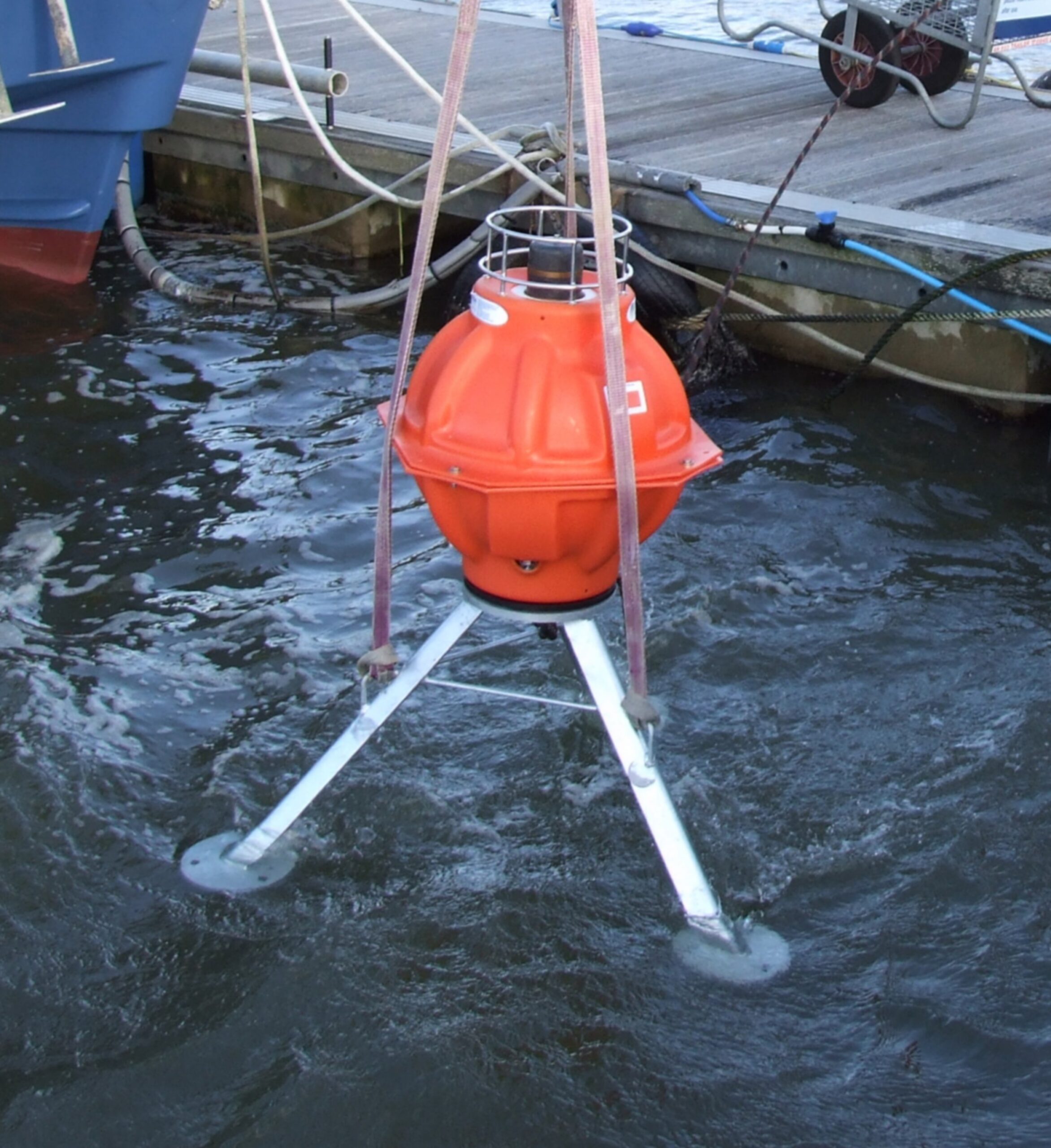
The GeoSEA array consists of 23 AMTs deployed from the German Research Vessel Sonne in late 2015 and comprises three sub-arrays that monitor different sections of the megathrust. The tectonic nature of the seabed gives rise to a variety of complex topographies.
Sonardyne’s in-house Survey Support Group worked closely with scientists from GEOMAR to plan the subarray layouts. Positioning of the AMTs were based on multibeam data collected during the preceding research leg. Precise placement in the order of a few tens of metres was required and in one case, an AMT had to be sited on a ledge on the side of a ridge that was only 50 metres wide and 150 metres long.
The first area is located on the middle continental slope between the main trench and the Chile coast and consists of eight transponders laid in pairs on a stairway-like feature of four topographic ridges at a depth of around 2,800 metres. The ridges, which are surface expressions of faults at depth, are approximately 100 metres high with around an 800 metre flat area between.
On the opposite (seaward) side of the trench from Chile, a further five AMTs were deployed in depths approaching 4,100 metres to monitor extension across plate bending related normal faults. Here, faulting of the Nazca Plate is caused by stretching of its surface as it is pushed downwards under the South American plate, and thus the fault lines are relatively new and active. The AMTs were laid at the intersection of multiple fault lines separating three or four blocks, with two being placed on the same block to provide a sound speed reference baseline.
The deepest area, located between 5,100 and 5,400 metres deep, is on the lower continental slope and comprises a circular pattern of eight AMTs surrounding two central instruments. This pattern provides a variety of short and long baselines to measure diffuse strain build-up in a highly faulted area made up of separate geological blocks, which are under high compression.
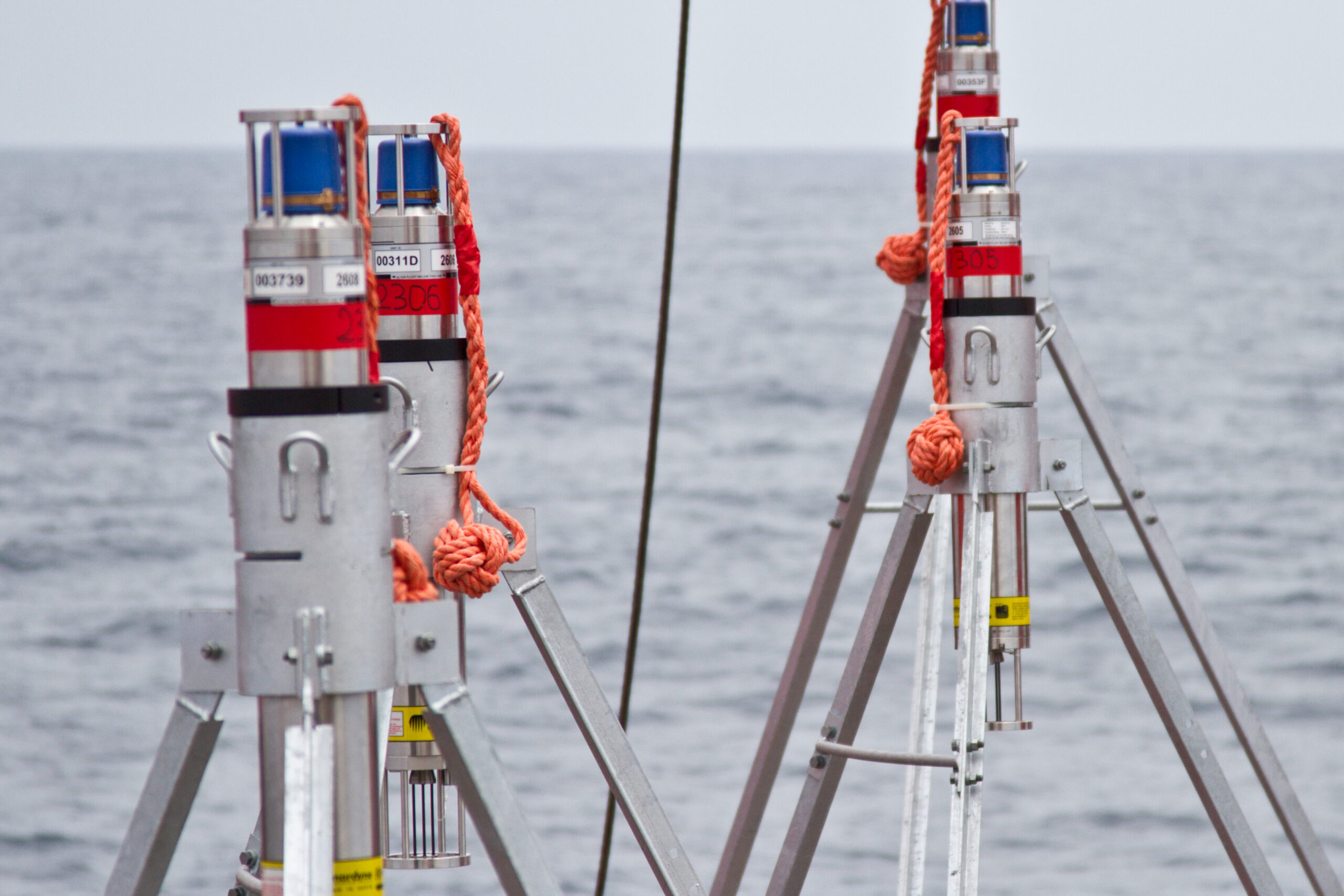
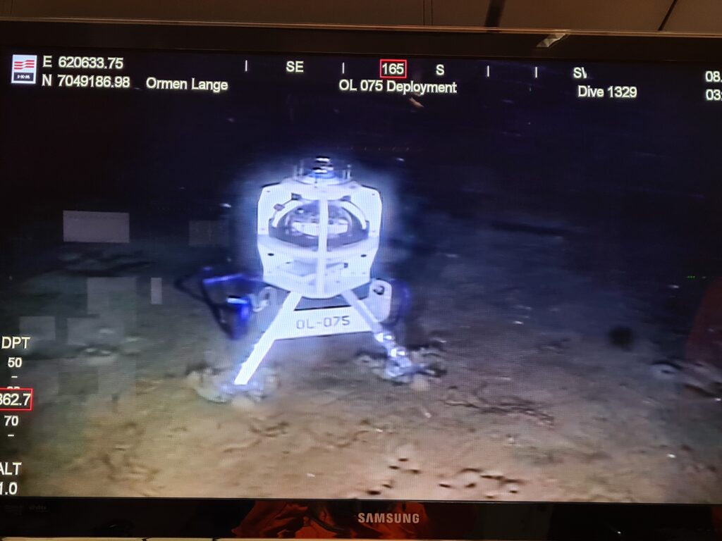
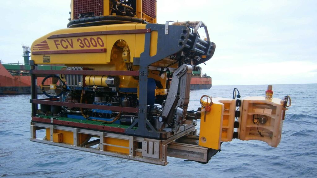
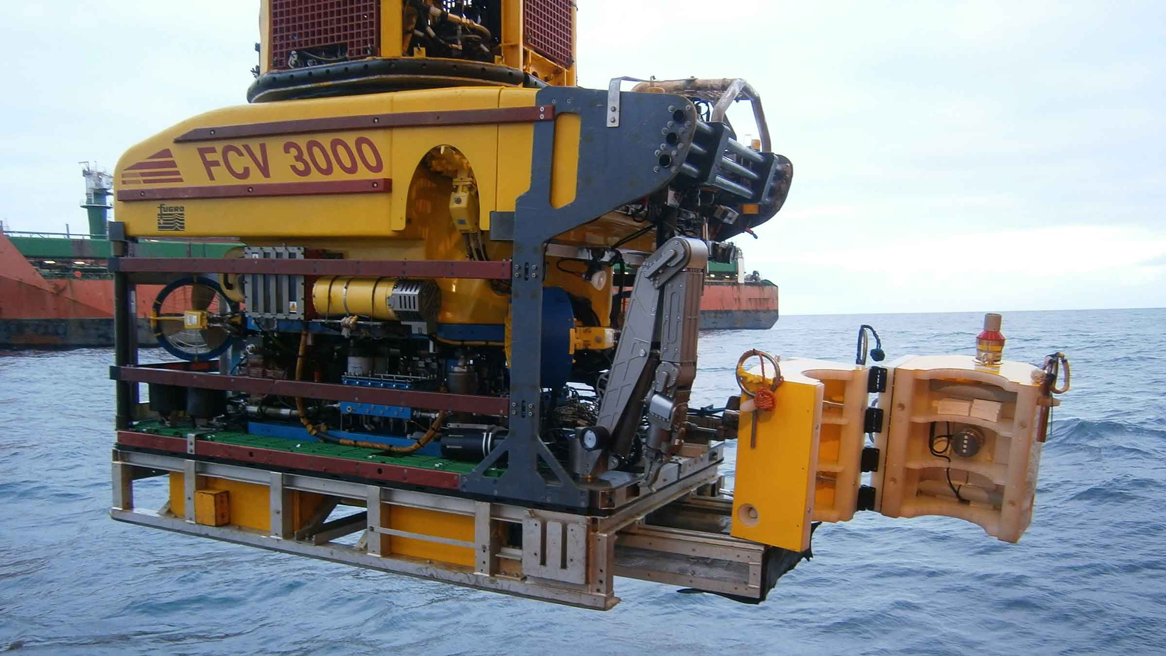
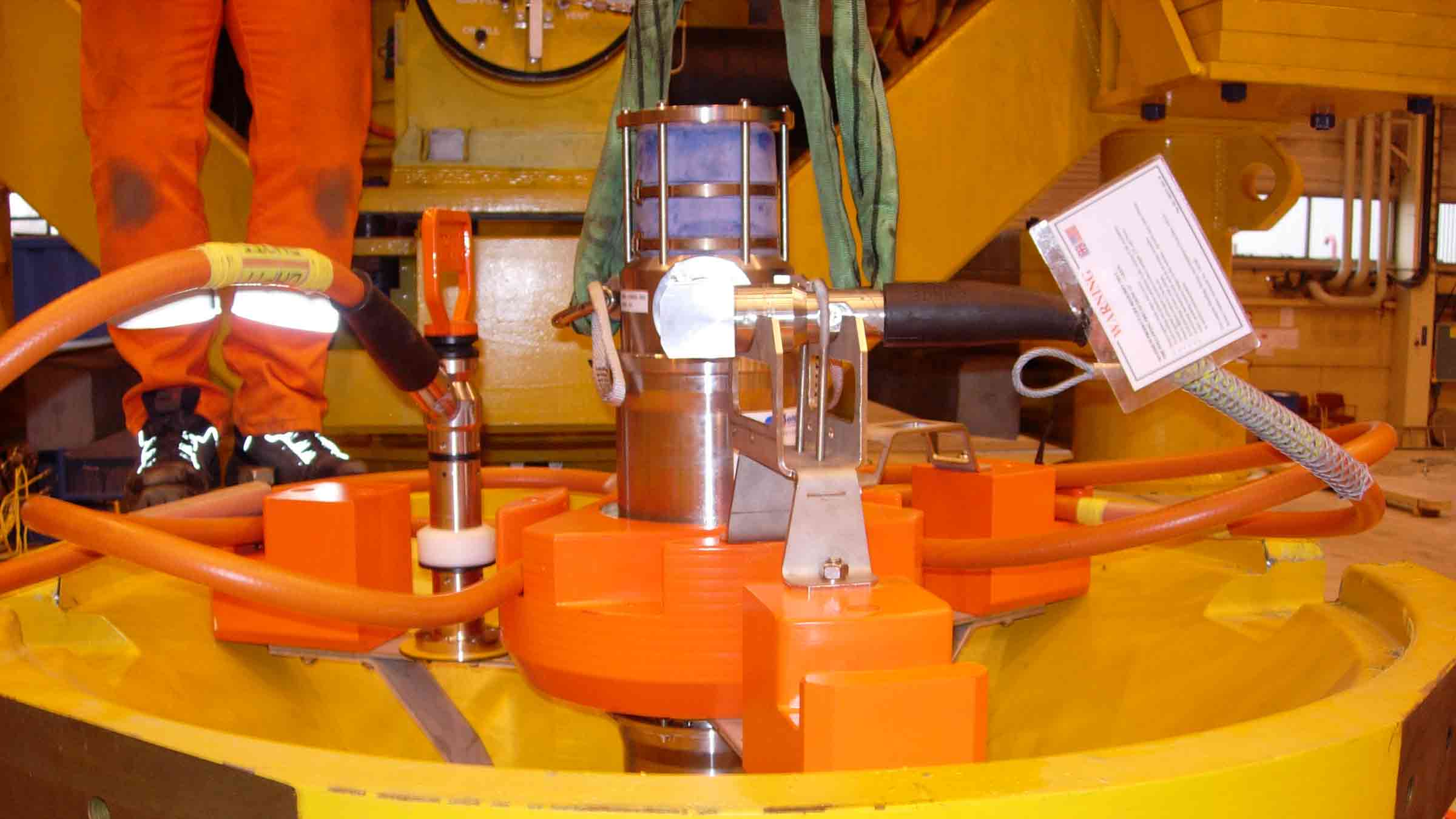
To cope with these extreme conditions, the AMTs used for the GeoSEA project are 6,000 metre-rated Lower Medium Frequency (LMF 14-19 kHz) omnidirectional units. Sampling at rates between one and a half and three hours, the GeoSEA AMTs are planned for an initial three and a half year deployment. However, the four metre high seabed frame in which each unit sits enables it to be easily removed by ROV, returned to the surface to allow its battery to be exchanged then placed back in the frame in the same position – giving scientists the option of extending the survey if required.
The results
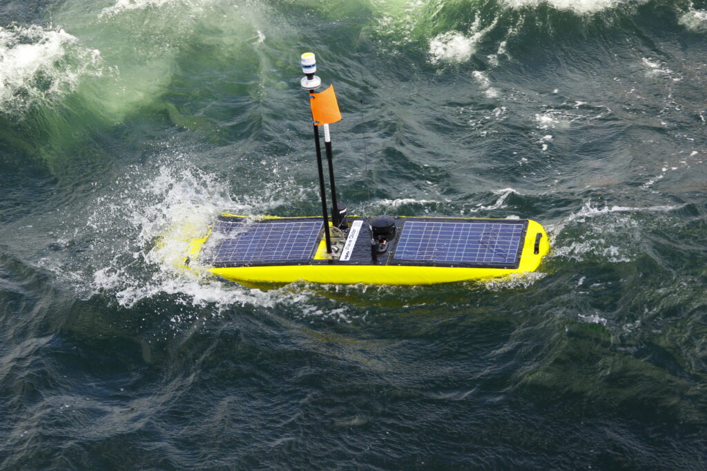
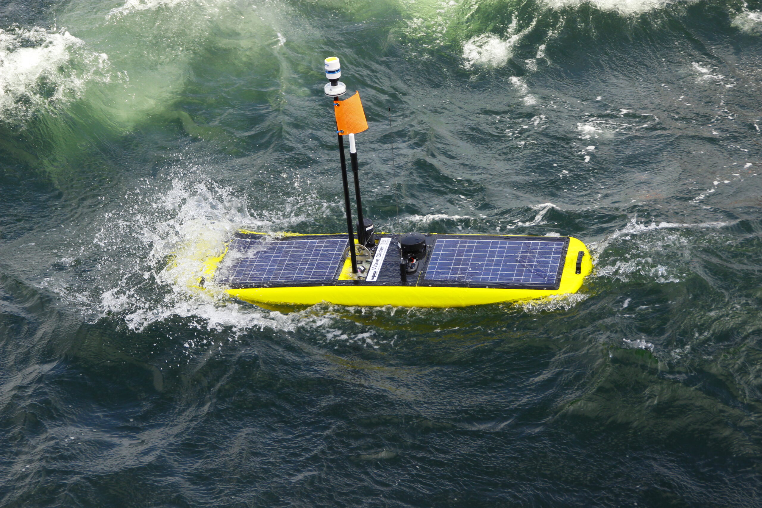
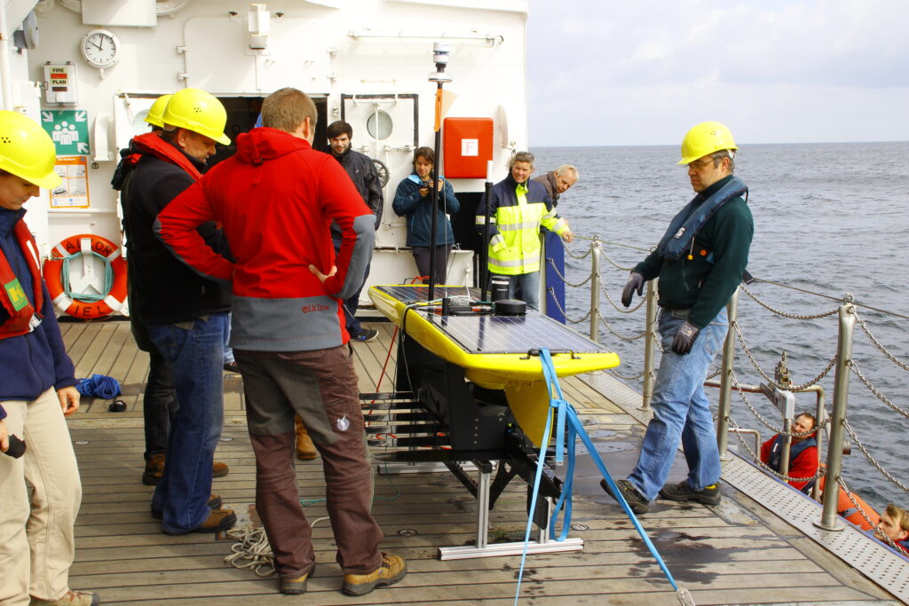
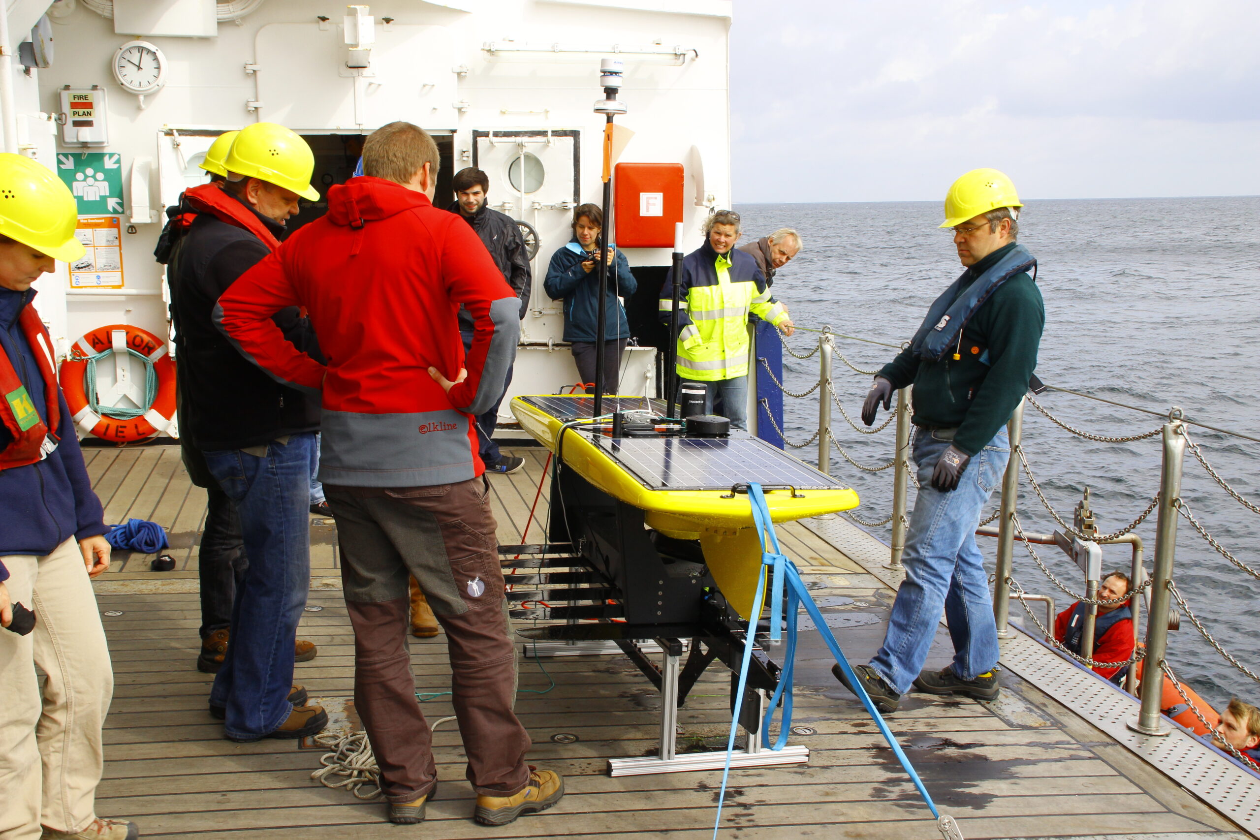
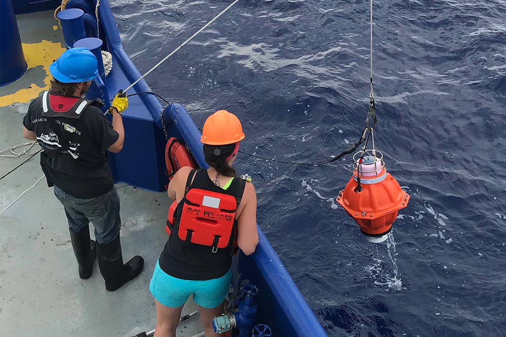
Since initial deployment, data from the array has been recovered by a US research ship using a Sonardyne HPT 7000 dunking modem deployed over the side, as well as GEOMAR’s GeoSURF Wave Glider, equipped with a 6G acoustic communication module fitted in its hull.
“Overall, our experience with Sonardynes instruments is superb and our results have been beyond our expectations. It has been a pleasure for us to work with infrastructure that we can fully rely on.” Professor Kopp from GEOMAR commented.
The success of the AMT’s performance in the Nazca-South American plate boundary arrays has resulted in two smaller arrays in the Sea of Marmara off Turkey and on the submerged flanks of Mount Etna. Although the results of these surveys were yet to be published at the time of writing, scientists were excited by the new opportunities Sonardyne’s technology offers.
GEOMAR’s Doctor Dietrich Lange summarises that, “With this approach, we are taking a new path in earthquake research since previously, measurements of a few millimetres, were hardly possible.”
Seismic operations in the transition zone
When seismic operations move into very shallow waters, accurately positioning seismic nodes or ocean bottom cables (OBC) on the seafloor can pose a challenge.
The challenge
The transition zone environment is often highly reverberant, the vessels used are often noisy and they can be a considerable distance from the acoustic transponders used to position the nodes. What’s more, shallow water makes nodes especially prone to movement, adding a further complication to proceedings.
Repeated node positioning operations conducted from vessels are costly and time consuming. Noisy environments can inhibit the quality of information and manned vessels are a costly option for completing work that can be done remotely.
The solution
To solve these issues, Sonardyne has created our TZ Transceiver. It’s very compact and simple to operate. Ideally suited to installation on manned workboats and USVs, it’s already being used for conducting acoustic positioning operations with seismic nodes deployed in the transition zone.
The TZ Transceiver works by collecting hundreds of acoustic ranges from transponders such as our TZ/OBC, TZ Transponder and Small Seismic Transponder 6. These are often attached either directly to the seismic node or to a deployment rope nearby. The ranges are merged with the vessel or USV’s GNSS data so that an accurate position of each node can be calculated.
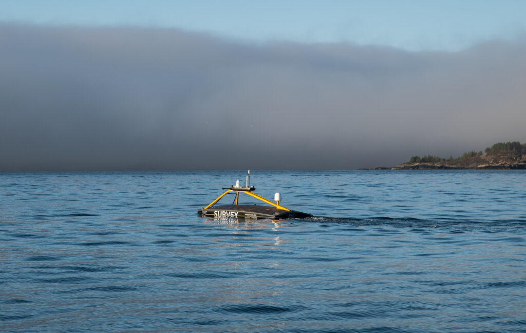
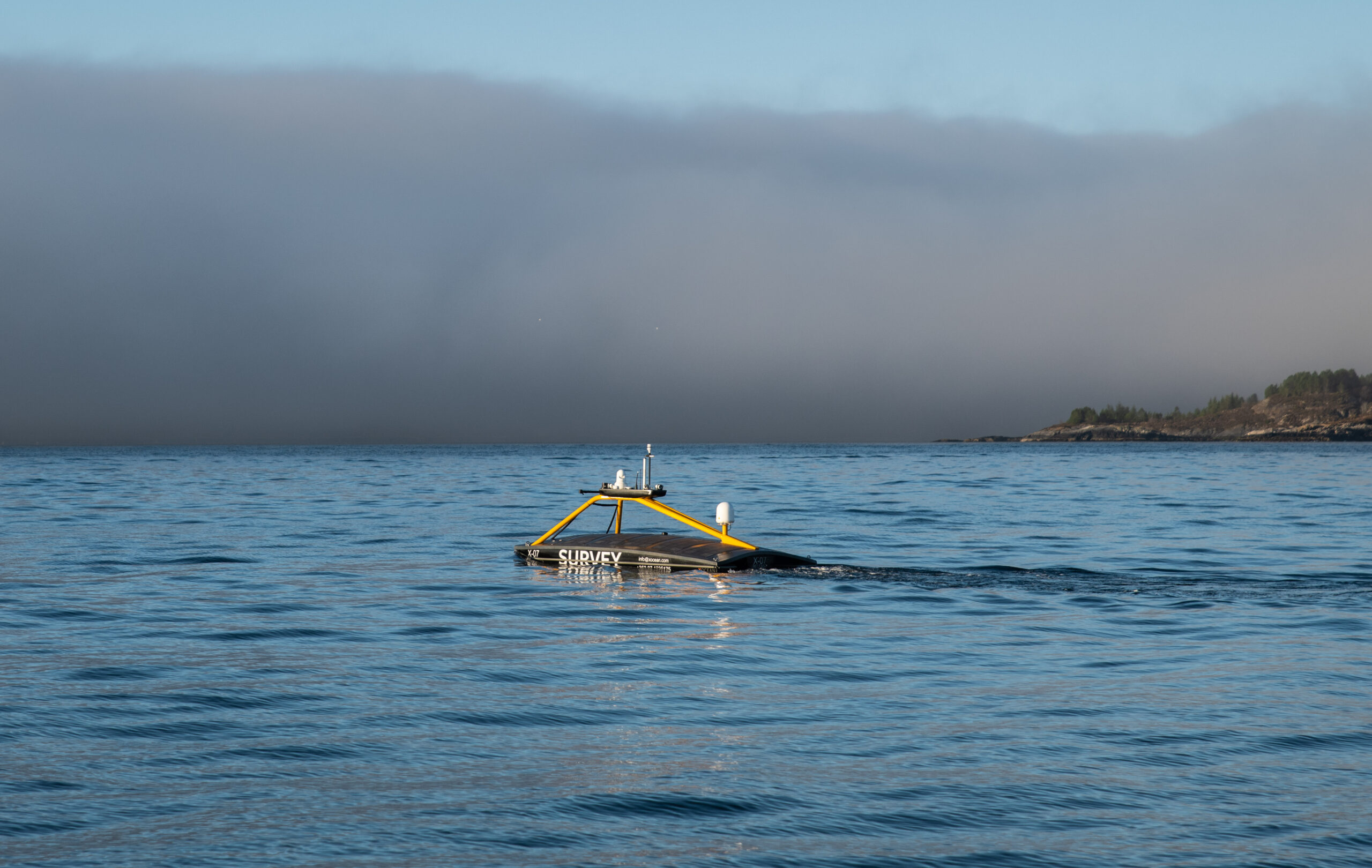
Mounting our TZ Transceiver onto a USV is ideal because it can follow the mother vessel autonomously and position the nodes as they are being deployed. Alternatively, it can be tasked to perform a position verification check to ensure the nodes have not moved.
The results
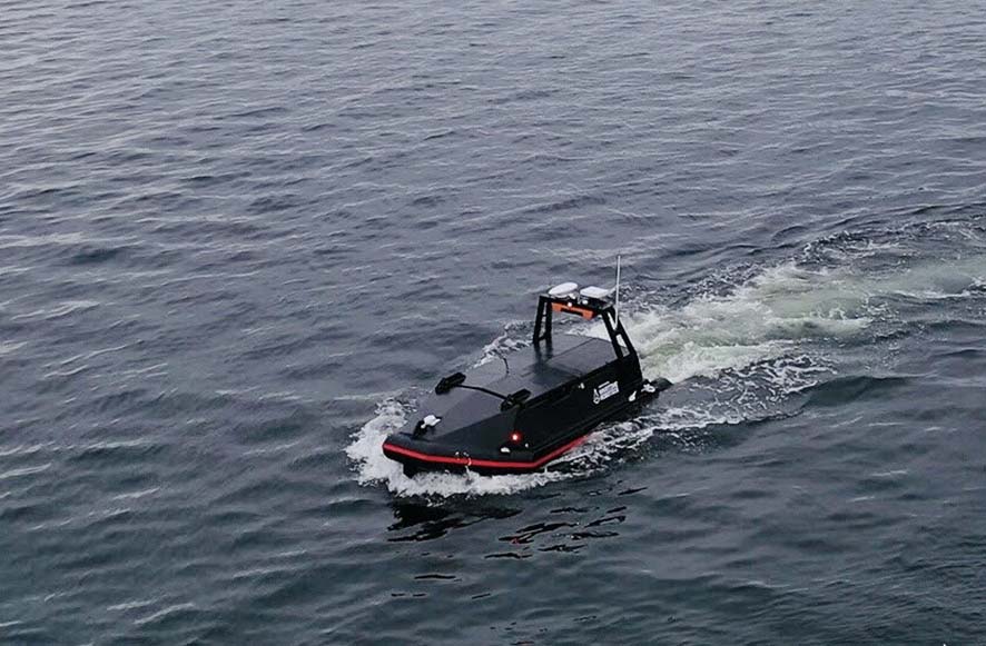
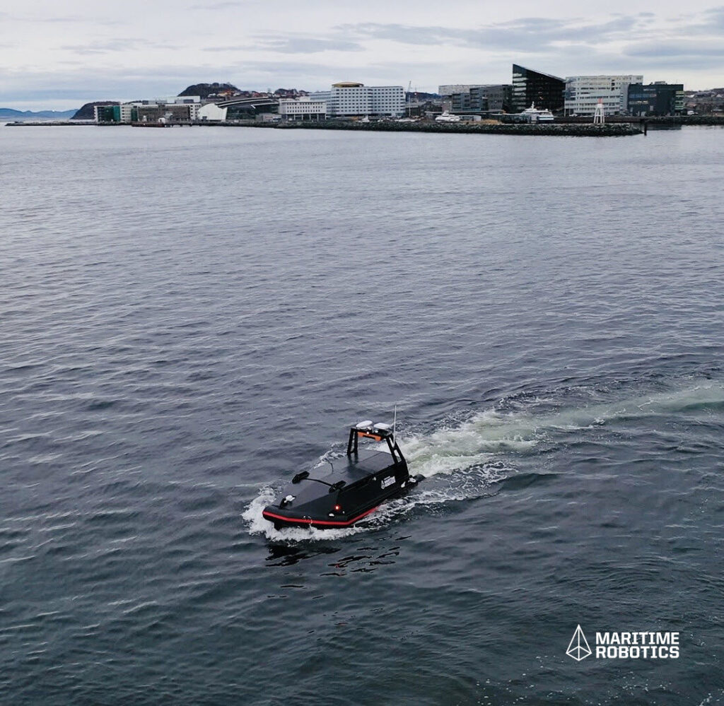
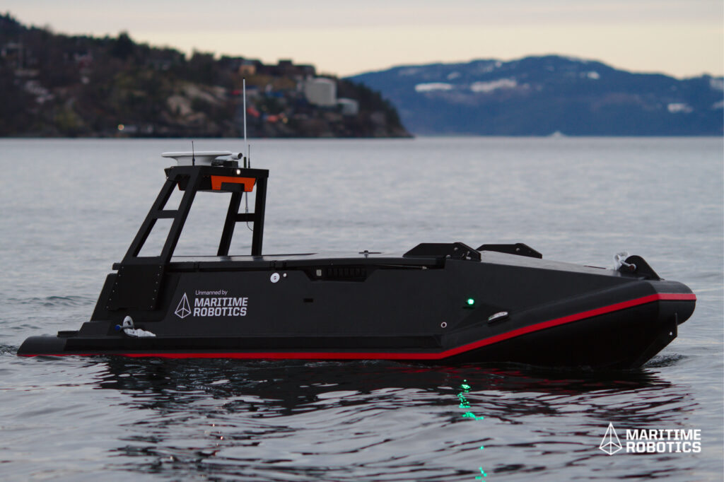
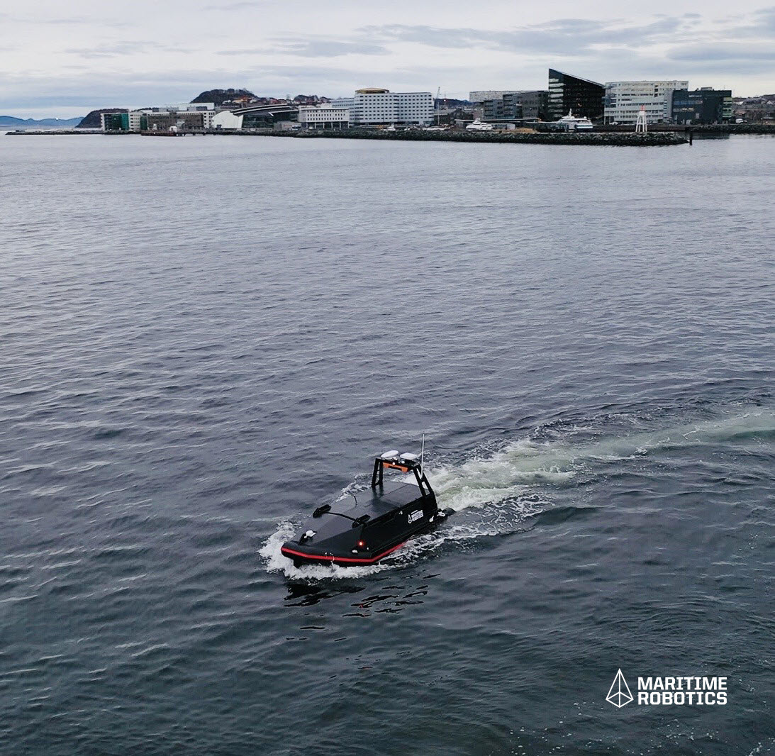
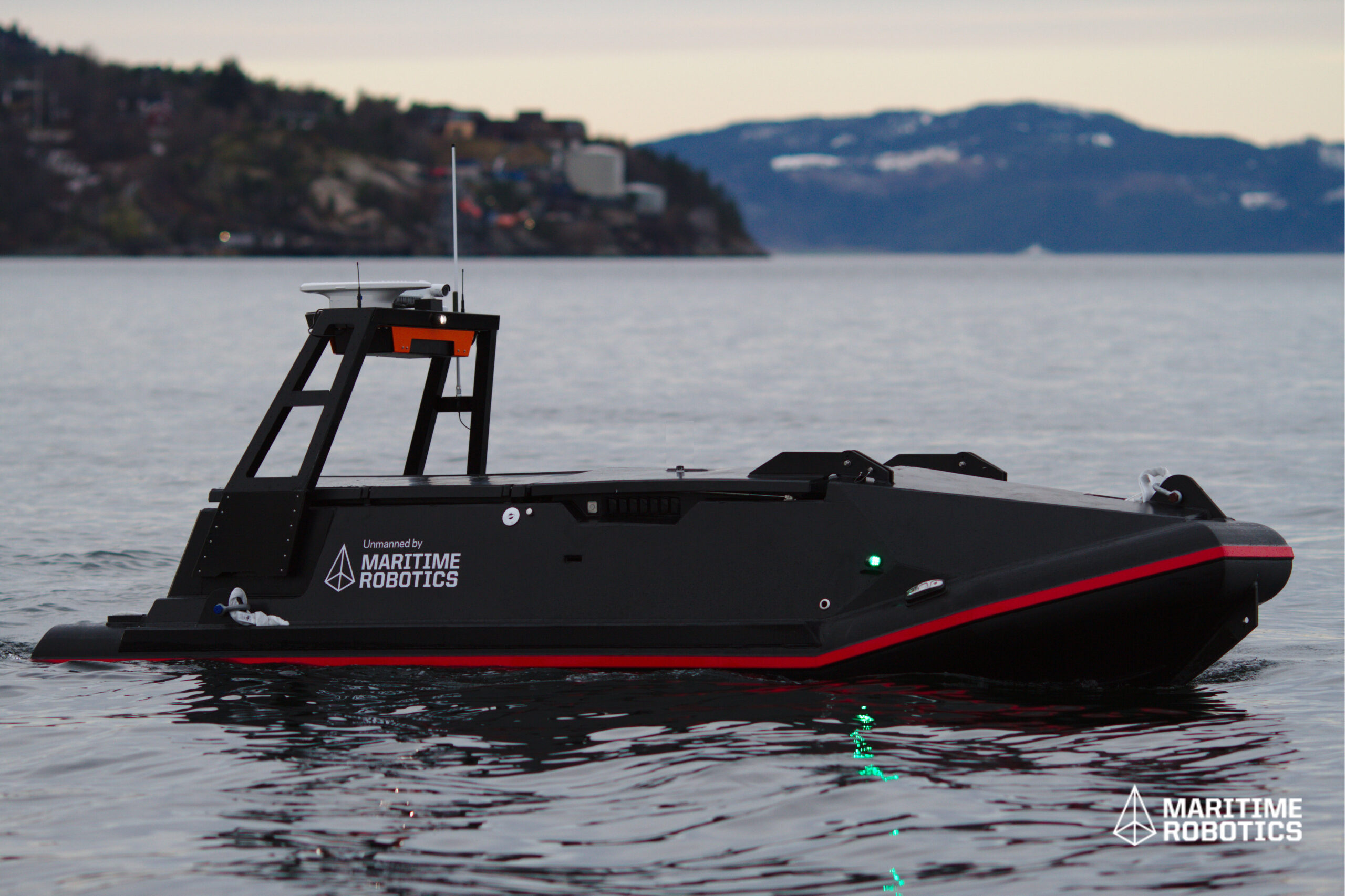
Fitting a TZ Transceiver to a USV such as the installation on Maritime Robotics’ Mariner USV is a very cost-effective force multiplier. The addition of the transceiver eliminates the need for a manned vessel to conduct the same routine operations.
Weighing in at 1,900 kg, Mariner is 6 m-long, 2 m-wide. It includes a moon-pool and an elevator mechanism for sinking and lowering sensors, such as our TZ Transceiver.
The vehicle is designed for both offshore and coastal applications and can be deployed and operated from a larger manned vessel or even over the horizon from a shoreside office. This increases the productivity of the existing survey crew as well as the overall profitability of seismic operations.
Measuring Mount Etna – an underwater monitoring first
A network of Sonardyne instruments deployed by scientists from GEOMAR Helmholtz Centre for Ocean Research in Kiel for 15 months has measured underwater slippage of the southeast flank of Europe’s most active volcano, Mount Etna.
The challenge
While satellite observations have previously shown that the flank of the volcano is slowly sliding towards the sea, until the establishment of this network, it had been impossible to confirm if and how the submerged segment was moving beneath the ocean.
Results published in the international journal Science Advances confirm that the entire flank of the volcano is in gravity-driven motion and in one event the slope slipped about four centimetres in just eight days. The risk is that sudden and rapid failure of the entire slope could result in a catastrophic tsunami in the Mediterranean.
The solution
A network of five Sonardyne Autonomous Monitoring Transponders (AMTs) were deployed in April 2016 by scientists at GEOMAR and Kiel University. The placement of the transponders covered the fault line that represents the boundary between the sliding flank and the stable slope. Three AMTs were situated on the sliding sector and the final two on the side of the fault line that was presumed to be stable.
The AMTs acoustically measure the distances between each other with a millimetric precision. This sound based underwater geodetic monitoring network, so-called marine geodesy, was a first for monitoring a volcano’s movement underwater.
Geraint West, Global Business Manager – Ocean Science told us “The AMT is a highly flexible instrument that has been used by research institutes around the world to measure seabed movements as diverse as rapid canyon turbidity flows to plate motion at deep subduction zones. This project is the first time that it has been used to measure the slippage of a volcano’s submerged flank.”
“The AMT was originally developed to measure deformation of the seabed caused by the extraction of hydrocarbons over several years.” Tom Bennetts, Sonardyne Projects Manager added.
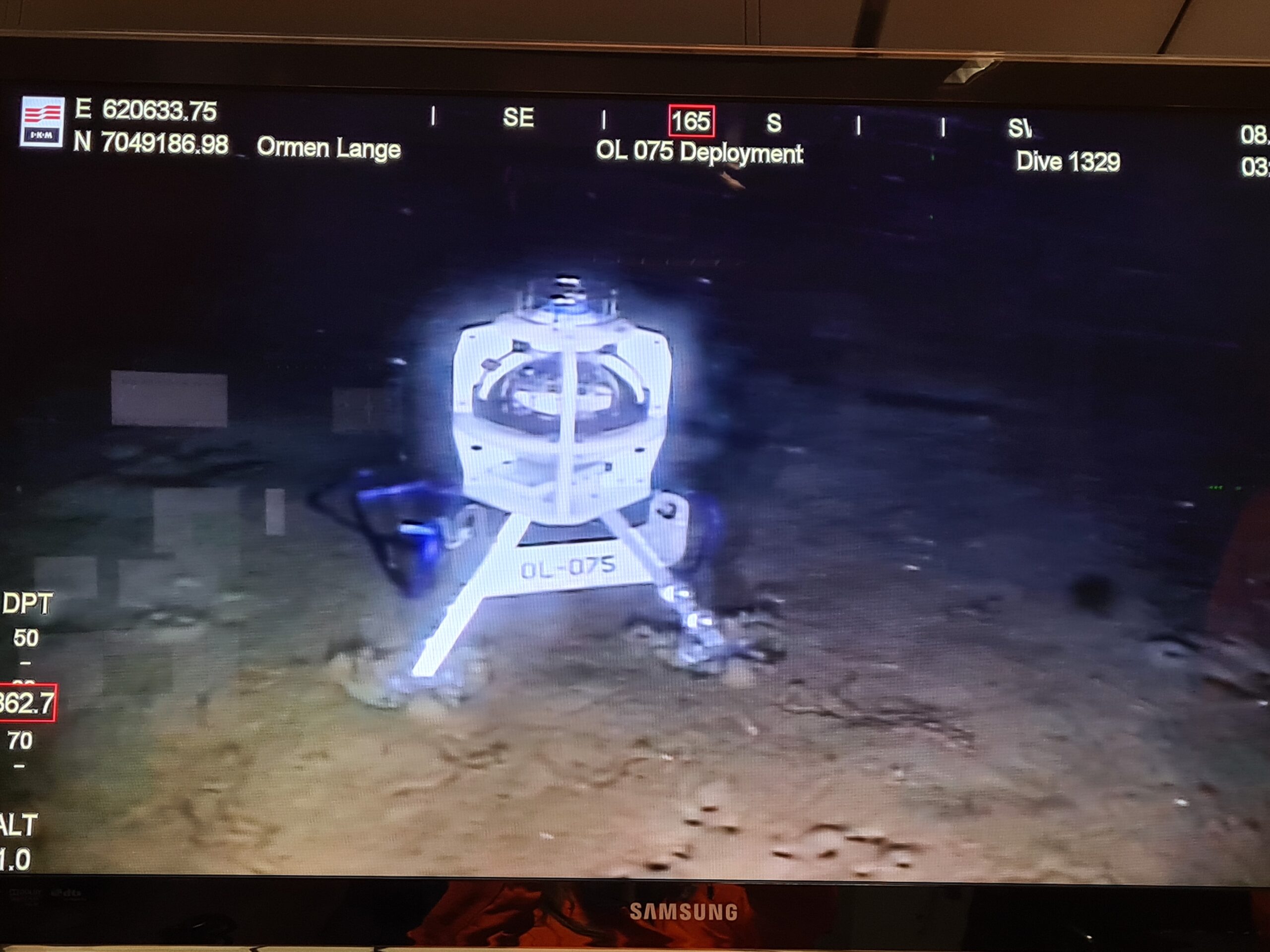
“Sonardyne first deployed AMTs on a large project over the Ormen Lange field in the Norwegian sector of the North Sea. For that project, some 220 individual instruments were deployed. The precision and endurance required for the Ormen Lange project showed us – and others – that our AMTs are also ideally suited for scientific studies of the seabed.” Bennetts clarified.
The results
The results published in the international journal Science Advances confirm that the entire flank of the volcano is in gravity-driven motion rather than the ascent of magma. One event saw the slope slip about four centimetres in just eight days. There is a very real risk that a sudden and rapid failure of the entire slope could result in a catastrophic tsunami in the Mediterranean.
Chris Hammersley, Project Engineer – Navigation Systems for Sonardyne said “Through several projects with major AMT deployments, we’ve built up a close relationship with the scientists and engineers at GEOMAR. We’re on standby to support them remotely through AMT deployment and routine data recovery missions. From our head office in the UK, we’re able to support these projects remotely, 24/7. For the Mount Etna Measurement project, we’ve been able to advise on optimal configurations for the instruments as well as troubleshoot any issues that arise, ensuring that GEOMAR have been able to use valuable ship time on site to best effect.”
The results of the study do not allow a prediction of whether and when a rapid failure of the slope might occur. For this reason, further research into the geological processes at and around Etna and other coastal volcanoes will continue. The success of our AMT deployments at Etna has secured the future use of sound-based geodetic monitoring networks for further studies.
Read more about GEOMAR’s project here.
Subsidence monitoring at offshore oilfields
Hydrocarbon production at offshore fields can cause seabed subsidence, potentially triggering dangerous geohazards including earthquakes and even fault slips. A long-term project with Norske Shell measuring seabed subsidence rates offshore Norway has now led to the latest, centimetric accuracy, long endurance autonomous instruments being developed and deployed, field-wide across the giant Ormen Lange gas field.
The challenge
The production of hydrocarbons at offshore fields causes a reduction in the pressure within the reservoir and therefore its ability to support the layers of rock above it. These layers are collectively named the overburden and they relentlessly push down on the reservoir sometimes causing structural instability surrounding the reservoir and deformation of the seabed into depressions known as a subsidence bowls.
The rate of seabed subsidence is of interest to geophysicists for two principal reasons:
Geohazard avoidance Because naturally occurring or production related subsidence has the potential to cause earthquakes and fault slips that can result in hydrocarbon leaks and/or damage to critical seabed infrastructure.
Geophysical interpretation To support identification of changes and minimise uncertainty in the reservoir, inform decision making by reservoir engineers and therefore help to maximize production and minimise risk.
Some offshore fields such as Ekofisk in the North Sea have subsided by several metres over their production lifetime, with average annual subsidence rates of 10-15 cm per year. However, many deep-water fields in regions such as the Gulf of Mexico and the pre-salt fields offshore Brazil exhibit much lower rates on the order of 2-5 cm per year, noting that accurate subsidence information is equally valuable to reservoir engineers operating at these fields.
In 2010, now retired Shell Geophysicist Dr Paul Hatchell set an industry challenge to develop a means to continuously measure seabed subsidence, over many years, that was sensitive enough to detect 1cm/year of vertical movement of the seabed and without breaking the bank in terms of the cost of operating a suitable monitoring solution.
The solution
Measuring subsidence rates to centimetric accuracies on land is comparatively easy using modern survey techniques such as GNSS and satellite altimetry. But radio waves from satellites do not propagate easily in seawater and therefore an alternative measurement approach was required.
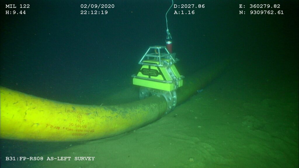
Sonardyne’s custom engineering team therefore implemented a pressure-based subsidence monitoring technique using a seabed deployed instrument called Fetch Pressure Monitoring Transponder (PMT). Each device houses highly accurate pressure sensors and data logging electronics coupled to a wireless acoustic communications modem for data telemetry and enough internal batteries to provide more than 10 years of operational life without human intervention.
At programmable intervals ranging from minutes to hours, Fetch PMT continuously measures and records raw seabed pressure, ambient temperature, unit inclination (tilt) and sample time data which is then harvested wirelessly by periodically deploying a compatible acoustic modem from a crewed vessel or latterly from Uncrewed Surface Vehicles (USVs). The use of USVs instead of crewed vessels is rapidly becoming the norm for this operation due to the significant reduction in cost and CO2 emissions and elimination of exposure to offshore personnel.
The Fetch PMT data harvesting process can be repeated whenever the most recent data are required with typical intervals ranging from three to nine months. The resulting pressure data are converted to absolute depth and then compared with previous data to calculate the rate of seabed subsidence in cm/year.
However, it is an unfortunate truth that all marine pressure sensors suffer from drift in their output readings over time and left unchecked this drift has the potential to reduce the effectiveness by which seabed depth and subsidence rate can be monitored. To address performance this issue, Sonardyne have employed three interrelated techniques:
We routinely pre-screen and measure the drift rates of all pressure sensors over a few months prior to deployment. Any poorly performing sensors are rejected and the resulting seabed pressure data from selected sensors is adjusted to compensate for the known drift signal.
We have developed a patented method of recalibration of the pressure sensors on the seabed using a technique called Ambient-Zero-Ambient (AZA) which is incorporated into our Fetch AZA PMT instrument. This instrument enables regular in-situ drift measurement and removal without recovery of the unit.
We can measure the absolute 3D position of each Fetch PMT unit on the seafloor using a USV based acoustic ranging process called GPS Acoustic Box-in (GPS-A) and can use this information to periodically calibrate the pressure sensor data.
Each of these techniques supports pressure sensor drift removal and therefore an increase to the sensitivity of the subsidence monitoring system towards the golden target of 1cm per year.
The results
High accuracy (circa 1cm/year) continuous seabed subsidence monitoring is now an industry recognized technique for offshore hydrocarbon production.
Several discrete subsidence events (sudden changes in depth) have been detected by the instruments used and this has provided geohazard information which has proven to be extremely useful to reservoir engineers who are tasked with determining the nature and potential causes of these events. Geophysicists also routinely use the information generated to reduce uncertainty in their reservoir models and to aid their decision-making processes as part of proactive reservoir management programmes.
Over the past 15 years, these systems have been deployed many times, starting with early trials at the Norske Shell operated Ormen Lange gas field in 2007, and then field-wide deployments of Fetch PMT and AZA PMT instruments across the globe including in the North Sea, Gulf of Mexico, Norwegian Sea and offshore Malaysia.
The latest deployment at Ormen Lange saw a total of 75 instruments deployed in two phases between September 2019 and October 2020 and these units continue to provide Norske Shell with invaluable subsidence monitoring data from this field, via crewed vessel and remote data harvesting missions conducted using an XOcean USV.
Costs, CO2 emissions and human offshore exposure traditionally associated with gathering oceanographic information have also been reduced by the routine use of USVs instead of ships to collect the data from the seabed wirelessly.
The technology has also been successfully transferred into Ocean Science applications for monitoring plate tectonics, subduction zones and the submerged sides of large volcanoes that, if they break free, can cause catastrophic Tsunamis.
As a result of our efforts to unlock the secrets of our restless sea floor, Sonardyne was recently awarded the 2021 Queens Award for Enterprise in Innovation, the highest award a UK business can receive.
Keeping production flowing by understanding subsea asset movement – wirelessly
An important feature of extending, or even preserving, offshore life of field is to know and understand what is happening with deployed subsea assets. Are they vibrating, perhaps they are slowly walking from their original position, is this happening as a one-off or regularly due to flowline properties? Oceaneering learnt all of this by deploying smart and intelligent sensors at a deep-water development offshore Africa.
The challenge
The worldwide quantity of flowlines, spool pieces, pipeline end termination units, risers and all manner of other installed subsea assets is staggering. All serve as important interconnecting elements in the overall offshore hydrocarbon supply chain. With an aging asset portfolio, it is sometimes very difficult to understand how these assets have been moving during their operational life and what this means to their accumulated fatigue figures and, therefore, safe end-of-life point.
At one offshore field development, Oceaneering, was set a challenge by an international operator. They suspected spool piece movement caused by slugging events, and asked Oceaneering Inc. to provide subsea data for third party analysis so the extent and frequency of movement could be determined. They hoped this would help with the introduction of mitigation measures that would ensure safe and controlled production from the connected producing wells.
With the field located in over 1,000 m of water and with no designed-in points for sensor mounting or hardwired connectivity, this was easier said than done.
The solution
Oceaneering turned to our wirelessly communicating and intelligent monitoring sensors called Subsea Monitoring, Analysis and Report Technology, or SMART for short. Additionally, a series of Autonomous Monitoring Transponders, or AMTs, were deployed within a seabed array to detect any longer period movement that SMARTs would be unable to detect.
Battery operated SMARTs were chosen as they incorporate a low-power inertial measurement unit, or IMU, that can precisely measure the installed sensor’s six degrees of freedom. This means that 3-axes of rotation and 3-axes of acceleration relating to the SMART sensor’s movement can be measured at very high sampling rates over a measurement window set by the operator.
This measurement window, which can be adjusted acoustically at any time from a topside transceiver, can be set between a minimum period of approximately 5 minutes to continuous recording. However, a one-hour measurement window is far more commonplace.
Once the measurement window has ended, SMARTs analyse the recorded raw data, producing and storing one statistical summary file for each window period. When required, these summary files can be requested for wireless transmission through the water column from each SMART’s location to a topside transceiver using Sonardyne’s fast and robust 6G Wideband 2 acoustic protocol on the Dunker 6 LBL and telemetry transceiver.
Importantly for the operator, all SMART raw, time-series, data is securely recorded and saved in-situ for more detailed analysis post-recovery.
Through the combination of edge analytics, low power electronics and acoustic communications, SMARTs could be installed for over a year. Even longer deployments are achievable by supplying larger battery packs or reducing the sampling frequency.
SMARTs are designed for high frequency motion monitoring, but the operator was equally concerned that longer periods of motion were in play that may have caused the subsea asset to gradually move from its installed position. Thus, monitoring for possible flow induced vibration (FIV) and vortex induced vibration (VIV) was also required. To monitor this motion, Oceaneering Inc. chose another Sonardyne sensor called an AMT.
AMTs are used for long-term survey and monitoring applications where instruments are needed to acquire acoustic ranges and other sensor data, like pressure, temperature, and sound velocities, without any surface control. By creating a Long Base Line (LBL) array of static seabed located AMTs with an AMT on the asset needing to be monitored, highly accurate measurements of any horizontal movement of the monitored asset can be measured, accurately timestamped, and logged. Vertical movement of the asset-mounted AMT can also be determined by the recording of precise pressure sensor information and comparing it to those from the control array.
An additional benefit identified by Oceaneering is that data from the AMTs can be wirelessly recovered using the same topside hardware as that of the SMART, resulting in less topside subsystems.
The results
Oceaneering mobilised the equipment in 2018 and it has been in operation ever since. The performance of the SMARTs in determining motion characteristics, coupled with the motion mitigation measures that were introduced, enabled the operator to continue producing safely and within the design life of the installed spool pieces. What’s more, the operator now has a far better understanding of their accumulated fatigue figures for the spool pieces and is able to determine the safe end-of-life point for their subsea assets.
Rapid leak detection for subsea production and storage sites
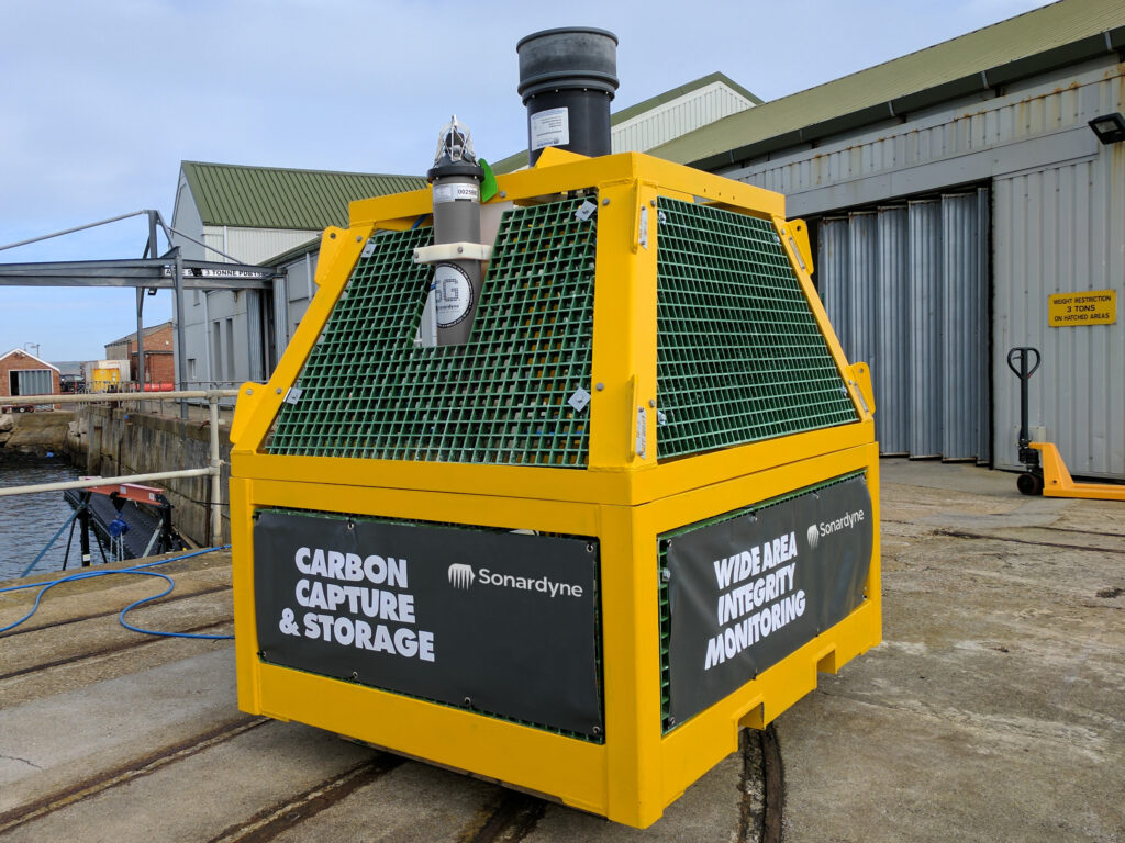
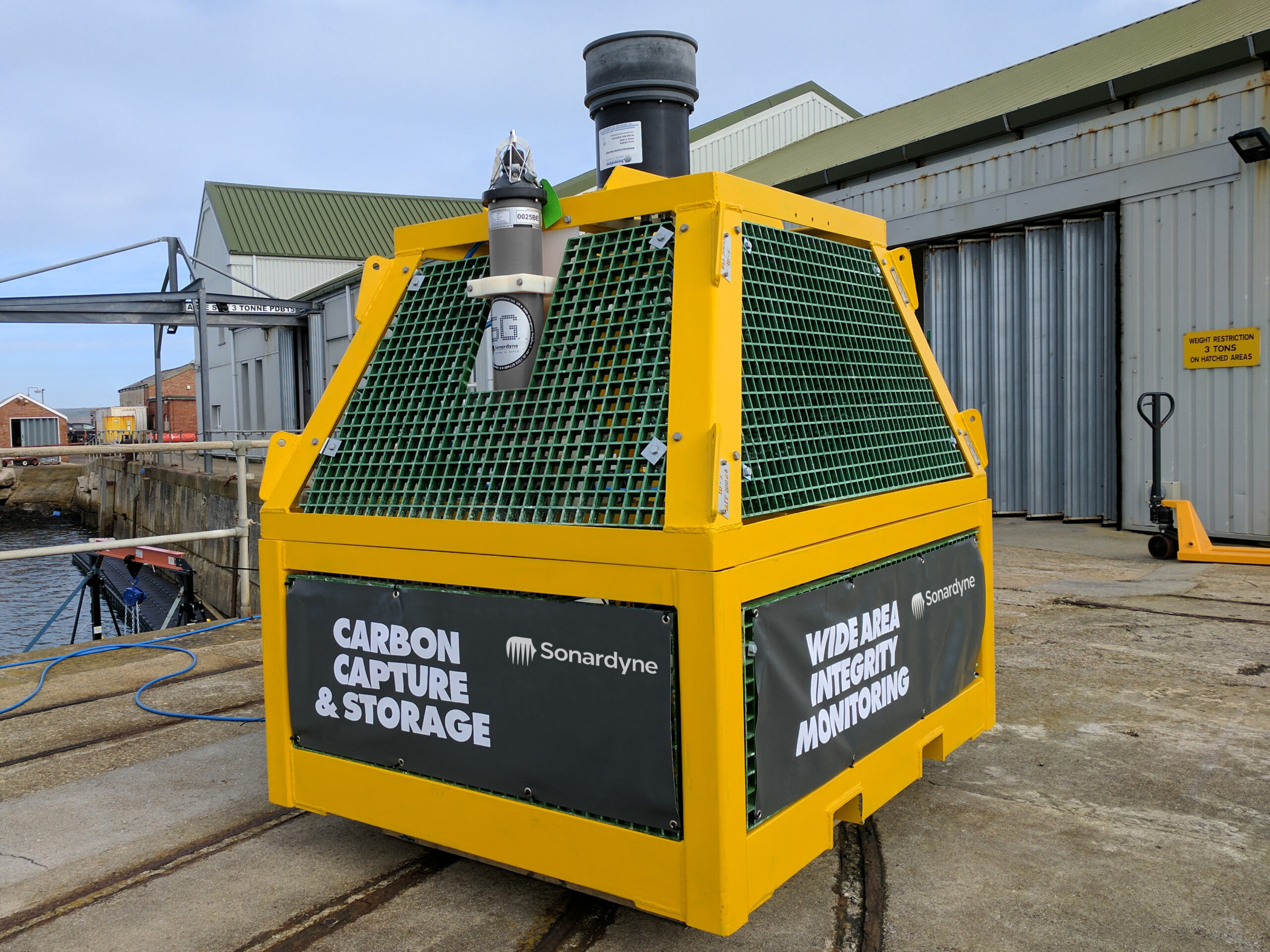
The ocean is a critical habitat that needs protecting. With decades of experience in sonar detection systems, our technologies provide an essential early subsea leak detection and warning system, across your oil and gas assets, CO₂ storage and offshore hydrogen transport and storage sites.
The challenge
A supermajor international energy company, with production infrastructure in more than 2,000 m (6,500 ft) of water depth, wanted a single subsea leak detection system that could be permanently installed to detect and localise, within seconds, oil or gas leaks across a wide area of its subsea infrastructure.
Existing sonar-based solutions are mostly based on sensors attached to subsea assets to detect leaks at specific or very localised locations, i.e. within a few metres. Alternative, non-acoustic, systems rely on anomalies in production data rates, which can be challenging should the leak occur upstream of the monitoring device.
At worst, leak detection relies on viewing the leak at the sea surface in the form of an oil-based sheen – when it’s already too late. This option is also limited when it comes to detecting leaks at gas producing fields and offshore carbon capture and storage (CCS) sites.
With a globally significant installed and aging asset base, as well as new infrastructure in the form of offshore CO₂ and hydrogen transport and storage, there’s increasing interest in alternative leak detection technologies that can operate autonomously and sustainably over wide areas in all water depths.
The solution
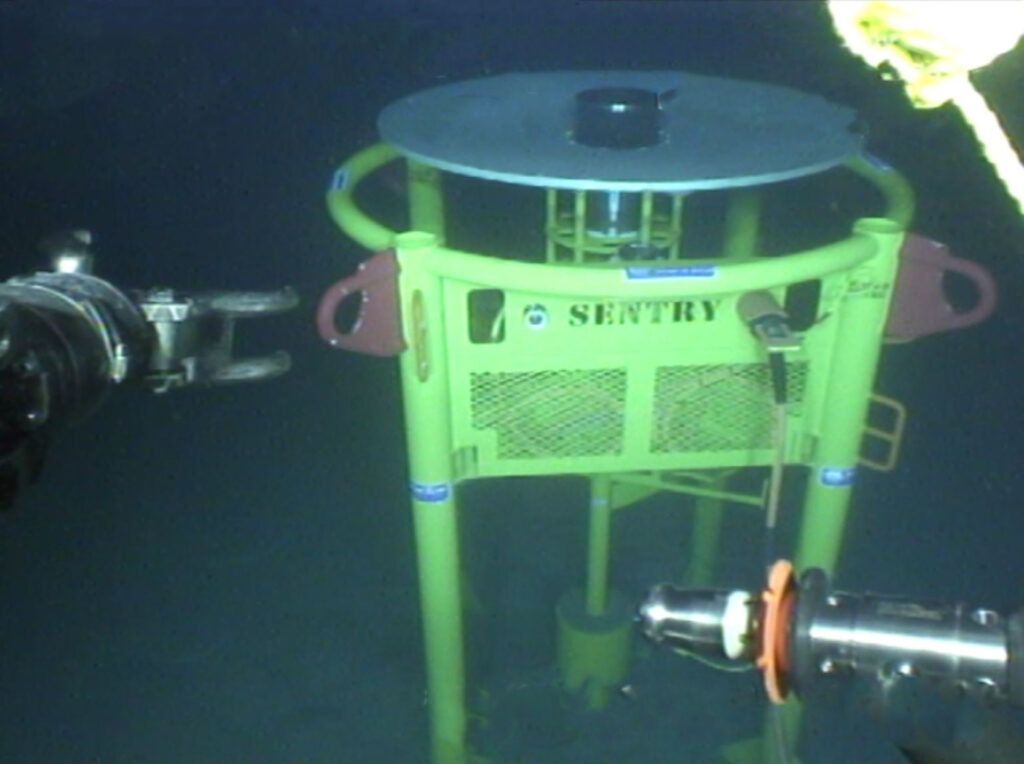
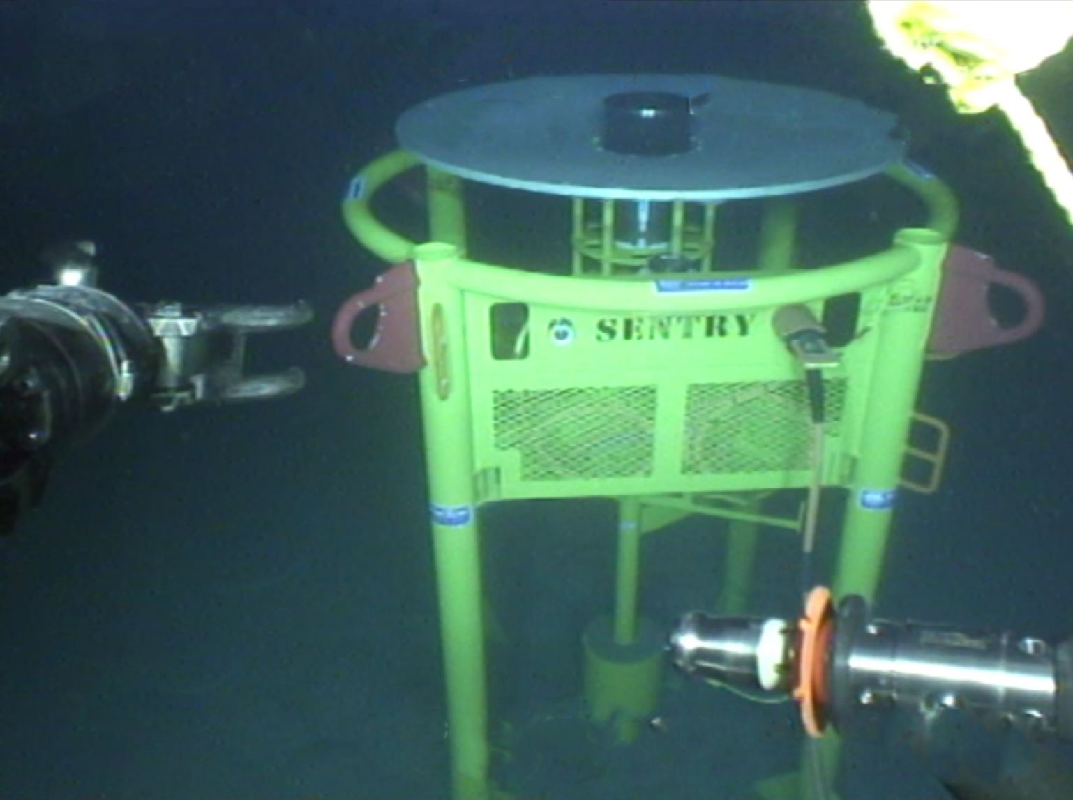
Developed by Wavefront Systems and manufactured and commercialised by Sonardyne, our Sentry Integrity Monitoring Sonar (IMS) is the only commercially available wide-area subsea leak detection system. A single Sentry head can provide 360-degree coverage of a 1,200 m diameter area, or more than one billion cubic feet of seawater, automatically alerting the operator as soon as an oil or gas leak is detected.
Detection rates are very impressive, with Sentry being able to detect monophase gas down to 0.1 litre per minute (equivalent to around 1 barrel of oil per day) or monophase oil to 1 litre per minute (equivalent to 9 barrels of oil per day). That means operators can react quickly to an infrastructure integrity breach before it becomes a bigger environmental and financial problem.
Sentry is an active acoustic-based solution that is based on a remotely operated vehicle (ROV) deployable low-power sonar proven for long-term monitoring. It’s available as a wired solution, that can be connected via existing subsea infrastructure directly into a surface asset. There, a Sentry workstation with graphical user interface (GUI) is able to provide users with clear real-time and automatic alerts of any oil or gas leaks.
It’s also available as a wireless, battery-powered solution for semi-permanent deployment, with data transmitted acoustically to a topside transceiver system. The transceiver can be deployed from a platform, buoy, vessel of opportunity or, now more commonly, via uncrewed surface vehicles (USVs).
The results
To make sure Sentry was fit for the oil major’s needs, the operator oversaw a trial deployment of a hardwired Sentry IMS. This included using a simulated monophase oil target, in this case nitrile-rubber strands, equivalent to a nominal oil leak rate of around 150 barrels per day.
The trials provided fast and accurate results. Detection and classification of the equivalent release of 100 barrels of oil per day out to 245 m (820 ft) was achieved, a distance constrained only by limitations of the trial set up. Leak detection was alerted within seconds of the simulated leak skid being deployed.
Sentry’s capability, however, covers 100 barrels per day mono-phase oil leaks at distances of up to 740 m (2,427 ft). It is even more sensitive to mono-phase gas leaks, with the system being capable of detecting down to the equivalent of just 1 barrel per day at 500 m (1,640 feet) or 100 barrels per day (as measured at depth) at 1,000 m (3,280 ft).
Following the extensive and successful trials, the operator purchased the Sentry IMS system for installation at its deep-water field development.
0
degree
coverage
0
m
diameter area
0.1 litre
per minute gas detection
Supporting the energy transition
As we transition from fossil fuels to new energies, many are looking to offshore as potential sites for CCS, as well as for hydrogen production.
Sentry helps to de-risk these projects. It ensures that, should carbon sequestration and offshore hydrogen transport and storage sites develop a leak, their operators will be alerted quickly, enabling a swift response, preventing larger environmental and financial problems.
Read about how we proved subsea leak detection capability for carbon capture and storage sites (CCS) through an Energy Technologies Institute research project, with partners Fugro, National Oceanography Centre, British Geological Survey and Plymouth Marine Laboratory here.
Repeatable, configurable, long-term surveillance
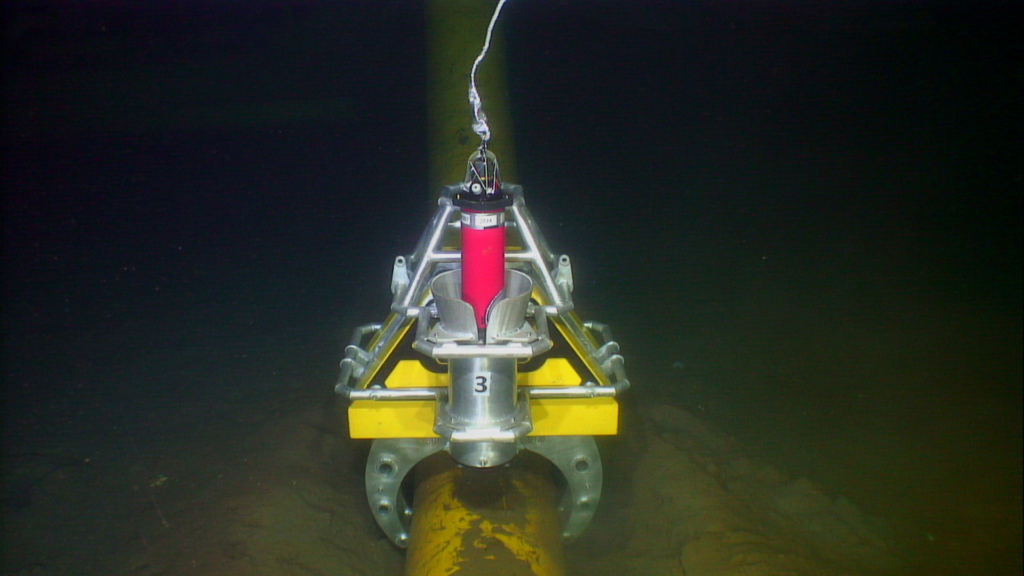
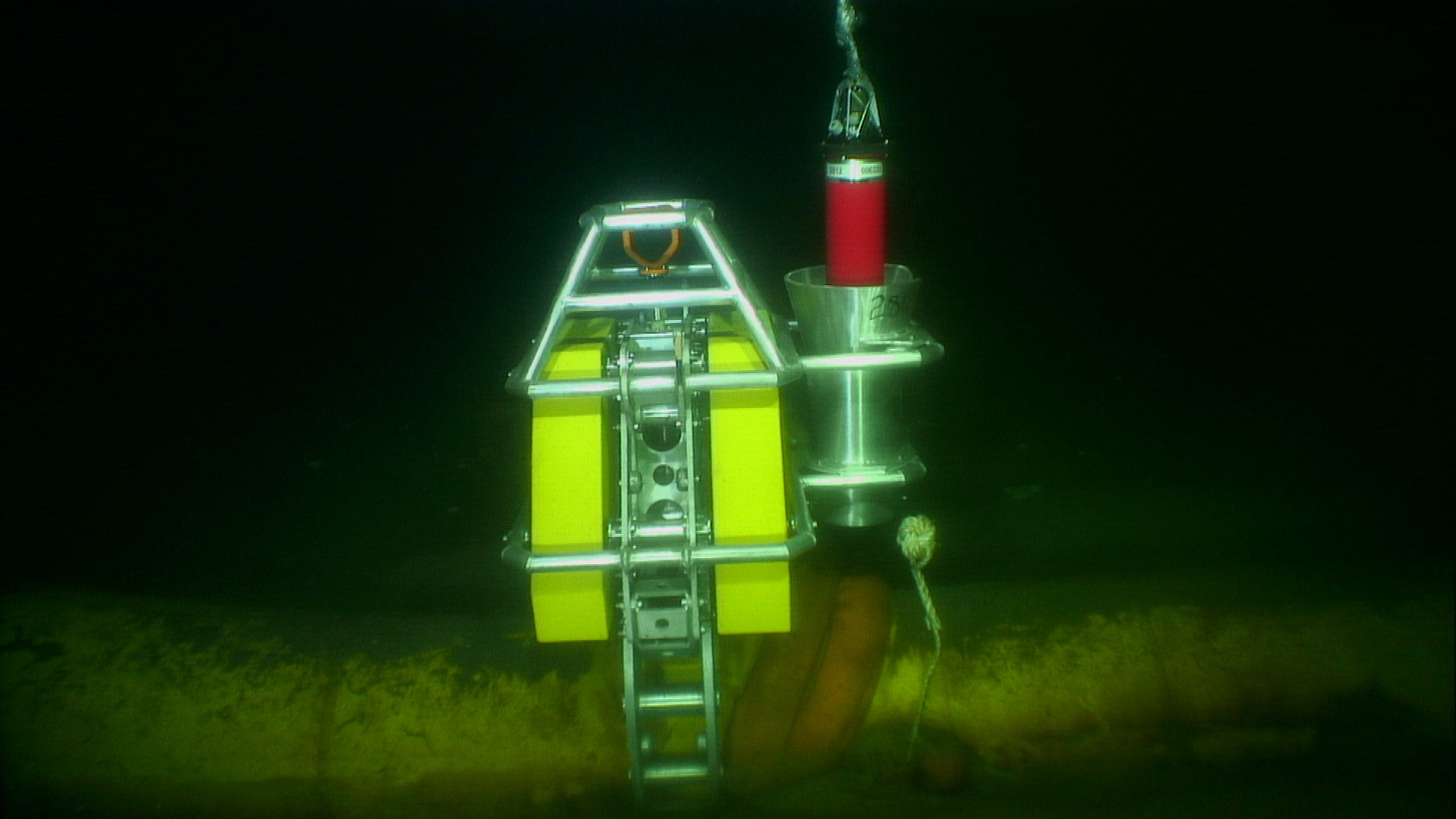
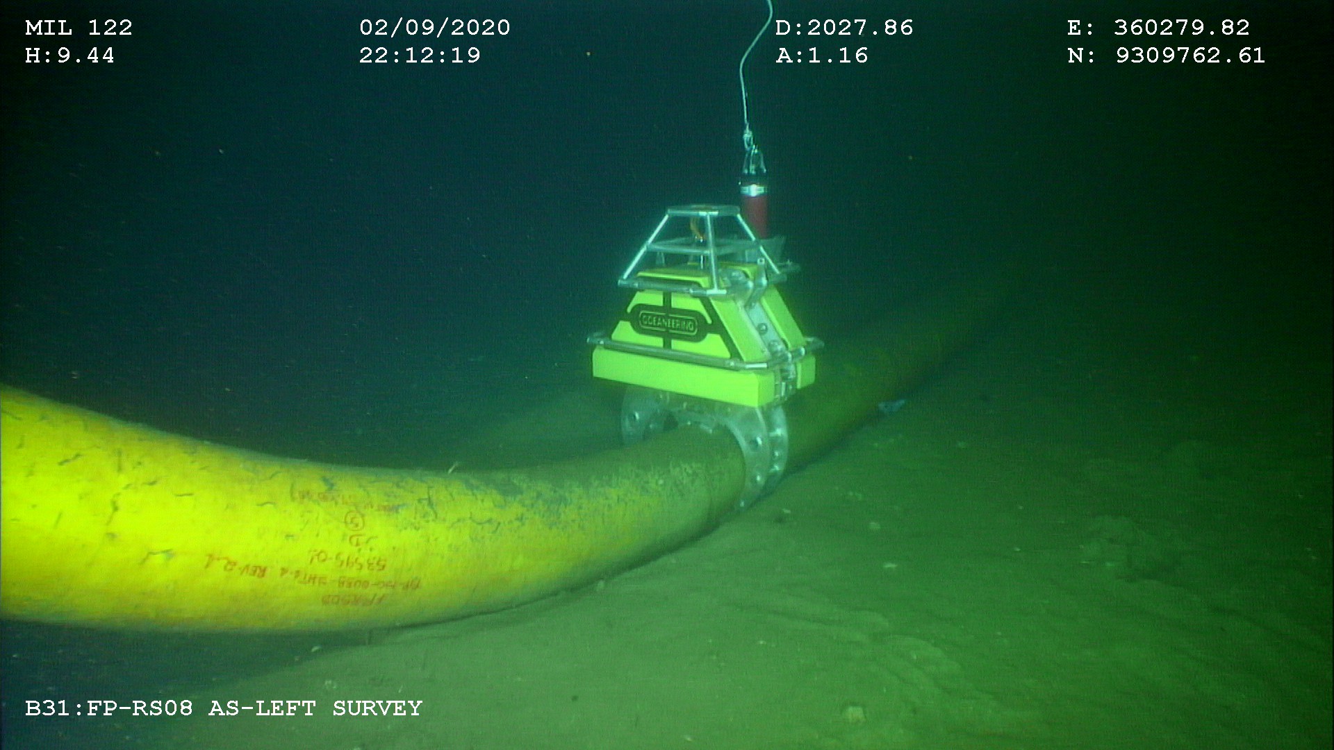
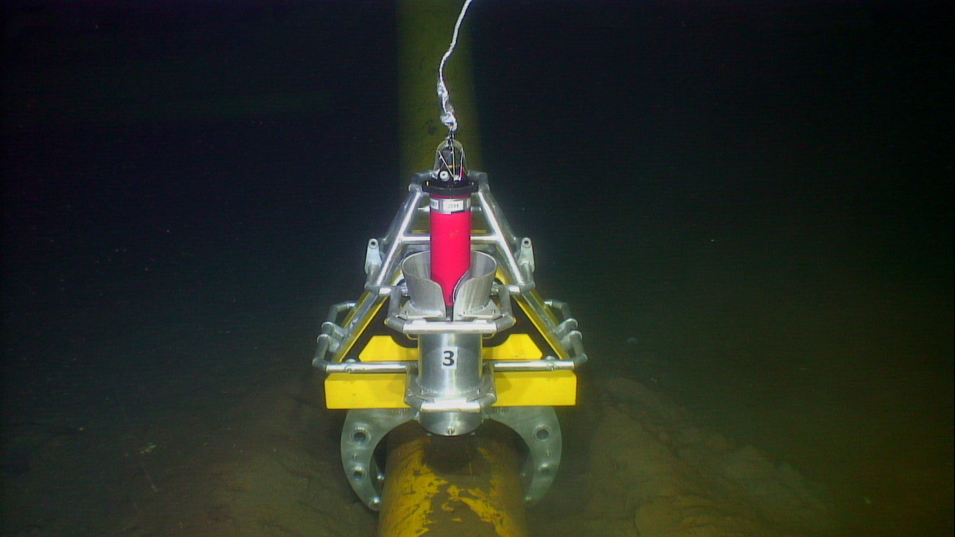
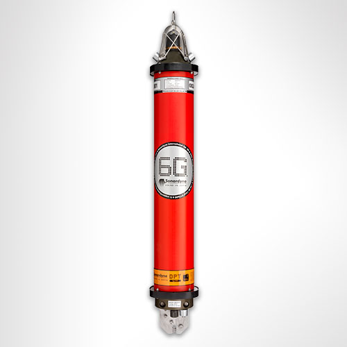
The Autonomous Monitoring Transponder (AMT) is a long-endurance transponder engineered for your long term subsea survey tasks and is capable of autonomously acquiring acoustic ranges and sensor data without surface control.
AMTs can detect subtle movement often not picked up by traditional ROV surveys so it’s ideal for monitoring slow movements, like creeping or buckling pipelines. Using structure and seafloor transponder buckets, they can be ROV-deployed, removed and re-installed to provide insight over time. Your AMTs can be configured to take measurements at specific intervals and be adjusted on-demand by you as your campaign progresses. Data can even be collected in real time using a USV should your operation need it.
As it’s collected, data is time-stamped and logged internally for recovery via the integrated high-speed acoustic telemetry modem. This autonomy allows measurements to be made over a long period of time without requiring a surface vessel or ROV to command the process. This enables new applications that save vessel and survey time so reducing cost and risk.
At a glance
- Recommended for long endurance site surveys
- Leave it deployed for six years or more
- Extensive choice of monitoring sensors
- Depth rated to 3,000 m
- Harvest data using a ship, buoy, AUV or USV
AMT has many of the same acoustic functions as Compatt 6, our most popular navigation transponder. It operates in the Medium Frequency (MF) band and is fully Sonardyne Wideband 2 compatible.
Precision pressure, temperature, sound velocity and dual-axis inclinometer sensors are integrated and are intelligently powered up at the requested time and sampling period, providing an ultra-low power platform for up to three years deployment. Sampling regimes can be re-programmed, and recovery of all data can be achieved via the acoustic modem.
The instrument is available with a range of omni and directional transducers, depth ratings and pressure housings dependent on deployment duration and application. Additional external sensors can be easily integrated via the power and communications port.
Acoustics
• Sonardyne Wideband 2 MF band (18 – 36 kHz)
• Over 500 unique addresses, ideal for large array deployments
• Data transfer rates of 100 to 9,000 bps – user selectable
• Omni-directional and directional transducers to suit environmental conditions
• Ranging precision: Better than 15mm
Sensing
• Standard onboard: Temperature, tilt, strain gauge
• Optional onboard: high precision stain gauge, DigiQuartz pressure sensor, high accuracy inclinometer, sound velocity
• Sampling rate: user configurable
• Vessel, USV or AUV data harvesting options
• Optional external: current meters, turbidity sensors
Design
• 3,000 m depth rating
• Aluminium or aluminium-bronze housing depending on environmental conditions and duration of deployment
• Can be deployed for over 5 years without recovery (maxi housing)
• ROV-friendly design: integrated acoustic release mechanism as standard
Ownership
• Warranty: 1 year return to Sonardyne service centre
• ITAR Controlled: No
• UK Export Licence: Not required
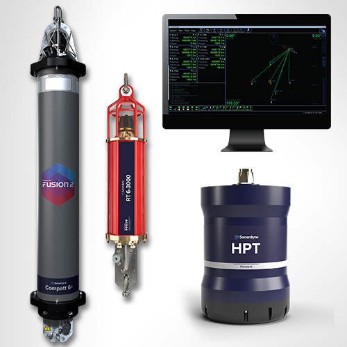
• A typical system: multiple seafloor and structure mounted AMTs (typically 6), vessel-based Modem 6 or Dunker 6 or HPT 5000 / 7000, SIU, Monitor software
Specifications
| Feature | Type 8305-3411 | Type 8305-3111 | Type 8305-3113 | |
|---|---|---|---|---|
| Depth rating | 3,000 m | 3,000 m | 3,000 m | |
| Operating frequency | MF (20–34 kHz) | MF (20–34 kHz) | MF (20–34 kHz) | |
| Transducer beam shape | Omni-directional | Omni-directional | Directional | |
| Transmit source level (dB re 1 µPa @ 1 m) | 187–196 dB (4 levels) |
187–196 dB (4 levels) |
190–202 dB (4 levels) |
|
| Tone Equivalent Energy (TEE) | 193–202 dB | 193–202 dB | 196–208 dB | |
| Receive sensitivity (dB re 1 µPa) | 90–120 dB (7 levels) |
90–120 dB (7 levels) |
80–120 dB (7 levels) |
|
| Ranging precision | Better than 15 mm | Better than 15 mm | Better than 15 mm | |
| Number of unique addresses Wideband 1 & 2 | >500 | >500 | >500 | |
| Battery life (listening, disabled) | Alkaline | 833 days | 833 days | 833 days |
| Safe working load (4:1) | n/a | 250 kg | 250 kg | |
| Mechanical construction | Aluminium-bronze | Aluminium | Aluminium | |
| Dimensions (length x diameter) | 1007 x 130 mm | 1034 x 134 mm | 1018 x 134 mm | |
| Weight in air/water | 35/24 kg | 24/12 kg | 24/12 kg | |
| Endcap sensors and options | ||||
| Temperature (±0.1°C) | Standard | Standard | Standard | |
| Tilt switch (±30-45°) | Standard | Standard | Standard | |
| Strain gauge pressure sensor (±0.1%) | Standard | Standard | Standard | |
| High precision strain gauge (±0.01%) Presens or Keller | Optional | Optional | Optional | |
| Paroscientific digiQuartz pressure sensor 1350 m, 2000 m, 4130 m, 6800 m (±0.01%) |
Optional | Optional | Optional | |
| High accuracy inclinometer range: ±90°, Accuracy: ±0.05° over 0 – ±15°; ±0.2° over 0 – ±45° | Optional | Optional | Optional | |
| Sound velocity sensor ±0.02 m/s accuracy under calibration conditions | Optional | Optional | Optional | |
| Release mechanism | n/a | Standard | Standard |
Frequently asked questions
Software and firmware
Software and control hardware
Datasheets
Manuals and quick start guides
Overview
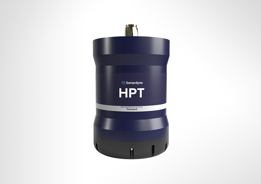
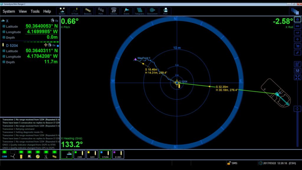
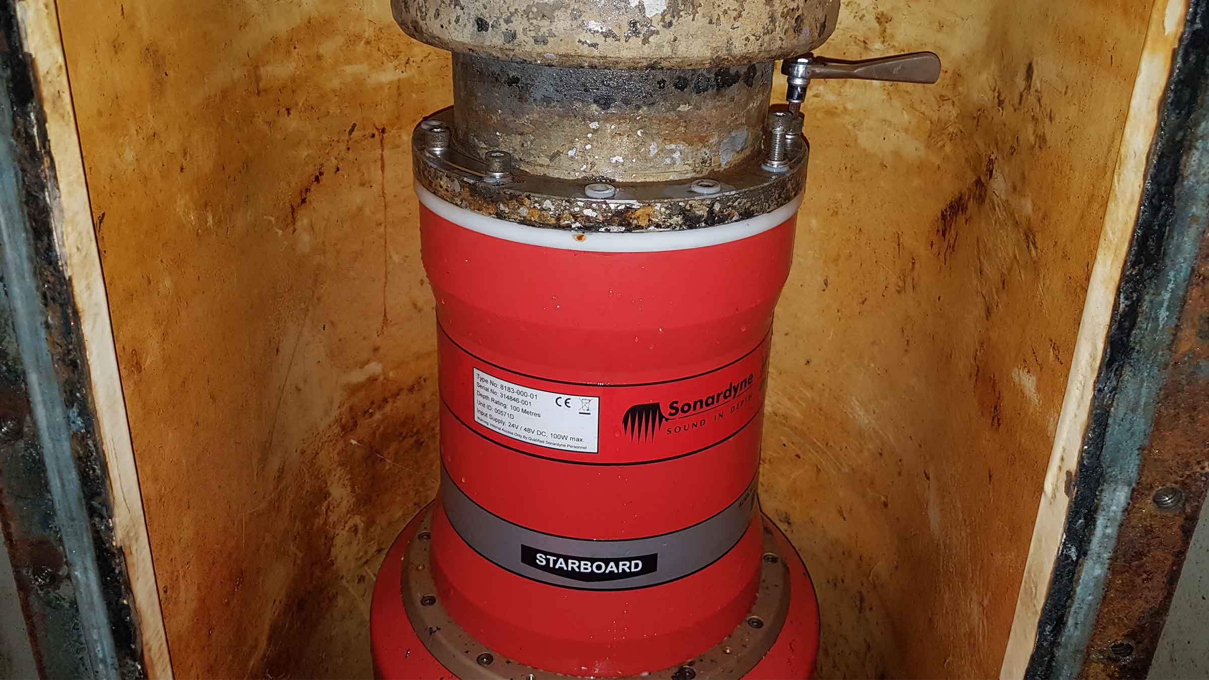
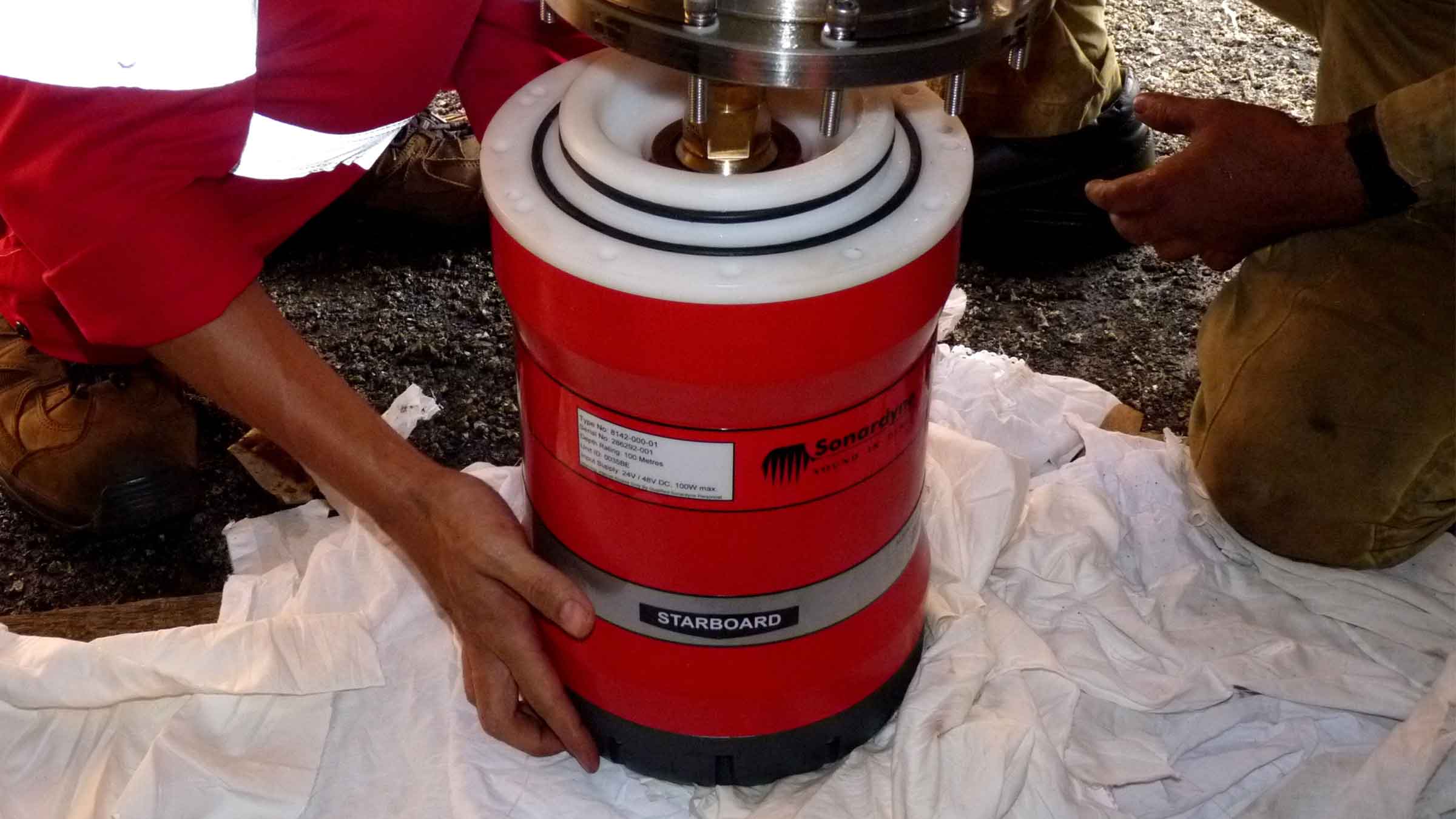
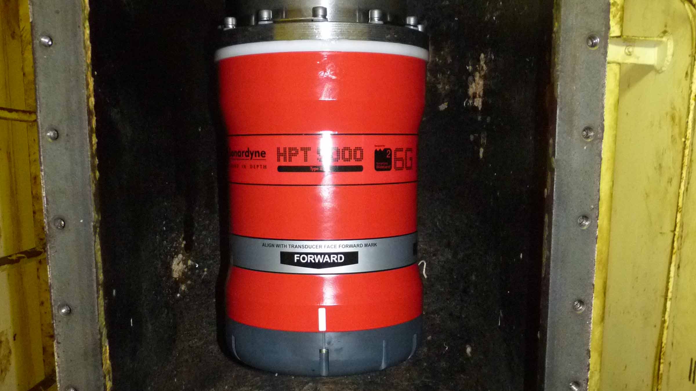
When it comes to USBL and LUSBL transceivers, one model does not fit all situations and vessels. For Ranger 2 and Marksman installations, our High Performance Transceiver (HPT) is available two primary configurations.
HPT 5000
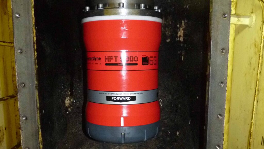
HPT 5000 offers full hemispherical acoustic coverage so it’s a popular choice for tracking multiple targets (ROVs, AUVs, towfish, seafloor sensors) over a wide range of depths and elevations. The unit is also suitable for dynamic positioning reference on survey, research and offshore support vessels.
HPT 7000
HPT 7000 is engineered for ultra-deepwater operations, tracking targets far below (rather than to the side) of a vessel, and also high vessel noise operating environments, as those typically encountered on DP drilling and construction where aeration from thrusters is liable to cause signal interference.
Both models of transceiver fully support 6G LBL operations using Fusion 2 LBL software. They are also highly capable acoustic communications modems, able to interrogate, command and recover data payloads from deployed Sonardyne instruments including AMTs and Fetch. Supporting telemetry rates of up to 9,000 bps minimises the time a vessel has to wait on location to recover data, as well as supporting LBL operations.
HPT 5000/7000s are also available in Gyro USBL configurations offering calibration-free installation and use.
At a glance
- Use with Ranger 2 USBL and Marksman LUSBL systems
- Can also be used to communicate and harvest data from Sonardyne sensors
- Hemispherical (HPT 5000) or directional (HPT 7000) arrays to suit your vessel and application
- Can be deployed other-the-side, through-tube or through-hull
- Suitable for new-build vessels or USBL/LUBL upgrade for your existing vessel
All HPTs are built on our 6G technology platform with multi-element processing to enable transponders to be positioned more precisely, more quickly and more robustly due to improvements in signal processing algorithms and array design.
Functionality such as ‘Discovery Mode’ enables vessels equipped with Ranger 2 and Marksman to enter an offshore area and automatically detect previously deployed transponders (including their configured address and channel), making simultaneous operations using shared seabed arrays possible.
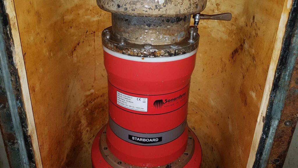
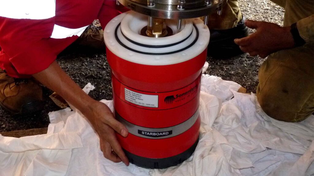
Manufactured in aluminium-bronze, HPTs are intended to be fitted temporarily or permanently to a vessel’s through-hull or over-the-side pole. HPT 5000s (including Gyro USBL 5000s) have also been fitted to large USVs for uncrewed missions controlled from over-the-horizon.
For specialist applications, inverted USBL, LMF frequency and extreme depth range HPT transceivers are also available. Please get in contact to discuss your requirements.
Ranger 2 in action
Optimising shallow water positioning for combined magnetometer and hydrographic surveys
Read moreAutonomous robots prepare to storm the ocean depths
Autonomous robots prepare to storm the ocean depths
A new world of multi-robot ocean exploration
Read moreSpecifications table
level, vessel noise, water depth, mechanical rigidity of the transceiver deployment machine, SV knowledge and proper calibration of
the total system using CASIUS.
| Feature | Type 8142-001 | Type 8142-002 (deepwater optimised unit) | |
|---|---|---|---|
| Operational frequency | MF (20–34 kHz) | MF (20–34 kHz) | |
| Transceiver performance |
Operating range | Up to 7,000 m | Up to 7,000 m |
| Acoustic coverage | Up to ± 90° | Up to ± 90º Optimised for deep water (depending on frequency of operation) |
|
| Range precision | Better than 15 mm | Better than 15 mm | |
| Positioning repeatability | All transceivers tested to better than 0.1% of slant range 1 Drms | All transceivers tested to better than 0.07% of slant range 1 Drms | |
| Transmit source level (dB re 1 µPa @ 1 m) | 200 dB | 200 dB | |
| Tone Equivalent Energy (TEE) | 206 dB (13 JA) | 206 dB (13 JA) | |
| Electrical | 48 V dc (±10%), Typical 15 W, Max 120 W |
48 V dc (±10%), Typical 15 W, Max 120 W |
|
| Communication | RS485, baud rate switchable, ethernet 100 Mbps |
RS485, baud rate switchable, ethernet 100 Mbps |
|
| Operating temperature | -5 to 40°C | -5 to 40°C | |
| Storage temperature | -20 to 45°C | -20 to 45°C | |
| Mechanical construction | Aluminium bronze | Aluminium bronze | |
| Dimensions (length x diameter) | 322 x 225 mm | 391 x 310 mm | |
| Weight in air/water | 26.7/15.3 kg | 46.9/29.0 kg | |
| Options | Tilted array adaptor | Tilted array adaptor |
Frequently asked questions
How to clean a transceiver array face
How to enter Transceiver & Lodestar Offsets for Optimised USBL
HPT Deployment Tests
Has anyone ever installed an echosounder and Ranger 2 USBL transceiver directly beside each other? Would this work?
How do USBLs work?
Does the HPT’s main connector need any maintenance?
When to use Depth Aiding
What acoustic address should I use for my USBL transponder
How to interface Ranger 2 into a 3rd party survey system
STP files
Software and firmware
Software and control hardware
Datasheets
Did you know?
Both HPT 5000 and 7000 are available in Gyro USBL configurations
Overview
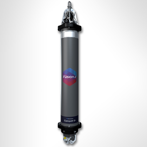
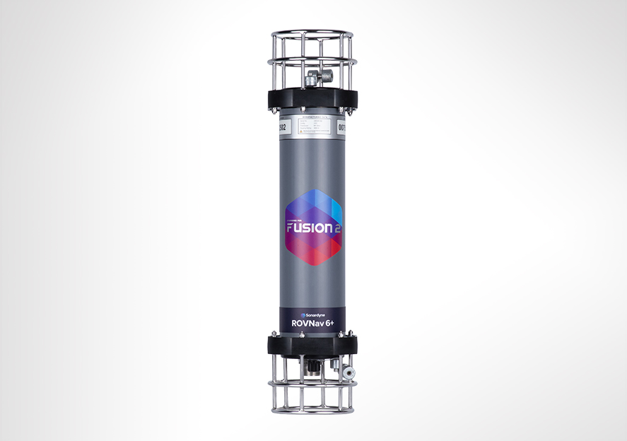
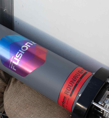
ROVNav 6+ uses our new Wideband 3 signal technology, which is key to unlocking the benefits of your Fusion 2 LBL system.
It allows, for the first time, sensor telemetry data (e.g. pressure, depth or temperature) from a seabed or structure deployed Compatt 6+ to be embedded within navigation (ranging) data. This change has a big impact on operations such as structure installation, as breaks in tracking to get sensor reading updates at vital moments are now a thing of the past.
Its compatibility with Wideband 3 and Wideband 2 telemetry commands, and support of high power Wideband 2 ranging protocols, proven for their accuracy and robustness, means the ROVNav 6+ offers improved range and acoustic performance in challenging conditions such as on noisy vehicles or in multipath environments.
At a glance
- High power, long range LBL transceiver for ROVs
- Wideband 3-enabled supporting embedded sensor data with ranging data
- Optimised for Fusion 2 and compatible with Fusion 1
- 3,000, 5,000 or 7,000 m depth rated options
- USBL mode for emergency ROV relocation
- Modem mode for harvesting data from Sonardyne logging sensors; Fetch, AMT…
ROVNav 6+ is also a fully functional USBL responder or transponder, compatible with Wideband 2 USBL systems and HPR400. The internal li-ion rechargeable battery pack also enables emergency transponder mode, so if the umbilical and therefore power is cut to the ROV it can still be located by USBL.
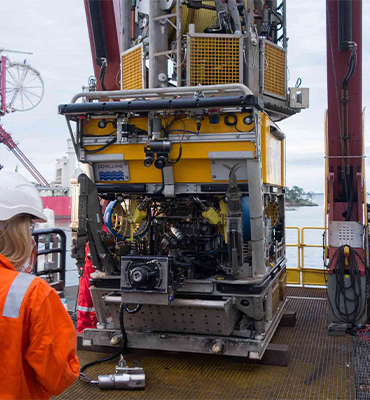
The omni-directional remote MF transducer makes installation on an ROV easy. ROVNav 6+ is designed to be rugged and relatively lightweight and utilises robust underwater connectors. ROVNav 6+ supports a range of internal sensors including: strain gauge pressure, PRT temperature and MEMS based inclinometer.
ROVNav 6+ is also fully compatible with our modem and logging equipment such as AMT and Fetch products, allowing it to be used to retrieve data or configure logging regimes. It supports all of our Wideband 2 and Wideband 3 spread spectrum acoustic communication; 100 to 9,000 bps data rates can be selected depending on the environment.
Sensor options include a Digiquartz pressure sensor, precision inclinometer and altimeter interface. This provides a fully featured ROV manipulator deployable tool/sensor pack for a range of different applications including metrology, bathy survey and structure deployment operations, without the requirement for any additional interfacing on the ROV.
Specifications table
| Feature | 8340-3161 | 8340-5261 | 8340-7261 |
|---|---|---|---|
| Depth Rating | 3,000 m | 5,000 m | 7,000 m |
| Operating Frequency | MF (20–34 kHz) | MF (20–34 kHz) | MF (20–34 kHz) |
| Transducer Beam Shape | Omni-directional | Omni-directional | Omni-directional |
| Transmit Source Level (dB re 1 µPa @ 1 m) | 187–196 dB (4 levels) | 187–196 dB (4 levels) | 187–196 dB (4 levels) |
| Range Precision | Better than 15 mm | Better than 15 mm | Better than 15 mm |
| Serial Communications | RS232 or RS485 (half-duplex) | RS232 or RS485 (half-duplex) | RS232 or RS485 (half-duplex) |
| Battery Life Li-ion (Listening) | 3 days | 3 days | 3 days |
| Operating Voltage | 24 or 48 V dc (±10%) | 24 or 48 V dc (±10%) | 24 or 48 V dc (±10%) |
| Serial Communications Connector | Subconn (8-way female) | Subconn (8-way female) | Subconn (8-way female) |
| Remote Transducer Connector | Burton (3-way male) | Burton (3-way male) | Burton (3-way male) |
| Housing Mechanical Construction | Hard anodised aluminium 6082 | Hard anodised aluminium 7075 | Hard anodised aluminium 7075 |
| Remote Transducer Mechanical Construction | Stainless steel 316 | Stainless steel 316 | Stainless steel 316 |
| Dimensions (Maximum) (Length x Diameter) | 768 x 200 mm | 768 x 200 mm | 768 x 200 mm |
| Weight in Air/Water | 14.3/5.3 kg | 14.7/5.7 kg | 15.5/6.0 kg |
Frequently asked questions
If I’m using Fusion 2, can I choose to use Wideband 2 or Wideband 3 telemetry?
Can ROVNav 6+ be used with standard Compatt 6s?
Will my ROVNav 6 work with Fusion 2?
Do I need to upgrade to Compatt 6+ and ROVNav 6+?
Where should I install my ROVNav 6+ transducer?
What are the differences between a ROVNav 6+ and Mini ROVNav 6+ ?
How to QC a Sound Velocity (SV) in Fusion 2
How far can my Compatt 6+ be above the seabed?
How do I perform an LBL calibration in Fusion 2?
STP files
Software and firmware
Transponders
Datasheets
Manuals and quick start guides
Technical bulletin
Did you know?
ROVNav 6+ is compatible with Fusion 1 and can be depth rated up to 7,000 m
