How can we help?
What acoustic address should I use for my USBL transponder
21 June 2021
Sonardyne’s 6G product range is designed for use in a wide variety of applications. To get the best performance out of the 6G family of hardware, the user can choose acoustic addresses linked to their acoustic operating frequency. These acoustic addresses are configured directly using Sonardyne’s 6G terminal software or even acoustically whilst in the water!
For USBL operations the user will usually be using either a Wideband 2 or a wideband 2+ acoustic addresses, these both operate between 19 and 32kHz. The difference between the two modes is that Wideband 2 addresses (which are appropriate for 90% of working conditions) utilise an 8ms navigation pulse compared to Wideband 2+ which utilises a 16ms navigation pulse. Whilst Wideband 2 is appropriate for the majority of applications, when operating in acoustically noisy conditions the longer pulse duration of the Wideband 2+ signal combined with the advanced onboard digital processing results in a more robust tracking solution. Users should note that if using Wideband 2+ it takes twice the energy to transmit these signals. Battery levels and consumption should be considered carefully.
Acoustic Address Families
Beacon addresses are broken down into channels with 14 addresses per channel. Each acoustic channel operates at a fixed frequency.
- The Wideband 2 family of addresses starts at 17xx (with individual acoustic addresses of 1701-1714) and finishes at 31xx (with individual acoustic addresses of 3101-3114).
- The Wideband 2+ family of addresses starts at 50xx (with individual acoustic addresses of 5001-5014) and finishes at 63xx (with individual acoustic addresses of 6301-6314).
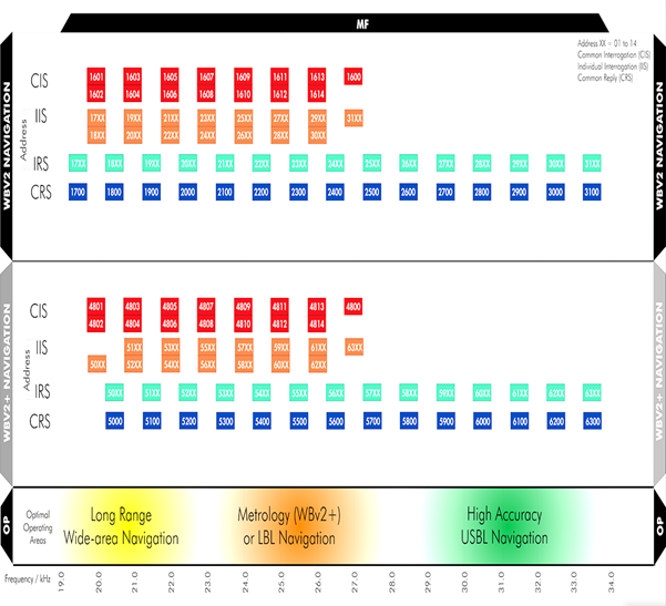
When configuring a unit for operation at specific frequencies, the user must be aware of the following terms, the two different interrogation/reply methods and the fact that the user will need to set both of these if trying to avoid noise sources.
- IIS (Individual Interrogation Scheme) – When only a single transponder is being tracked or when multiple transponders are being tracked with different update rates IIS may be used. Only a beacon with the correct acoustic address will reply to this interrogation.
- CRS (Common Reply Scheme) – CRS is utilised for the reply pulse of an IIS interrogation.
- CIS (Common Interrogation Scheme) – When interrogating multiple beacons, using a common interrogation scheme is advised, this is common practice with USBL and is much more efficient than individual interrogations as all configured responder will reply to the same initial interrogation.
- IRS (Individual Reply Scheme) – IRS is utilised for the reply pulse of a CIS interrogation.
Choosing an Address
When choosing an appropriate acoustic address, the following factors should be considered:
- Is there a need for longer range navigation? – The lower the frequency of the acoustic pulse the lower the attenuation of the water that the signal will travel through.
- Is there a noise spike within the frequency range? – Using the FFT (Fast Fourier Transform) functionality built into 6G hardware it is possible to identify noise spikes to be able to adjust operating frequencies to improve performance.
- Is the system operating in a noisy and/or reverberant environment? – As mentioned, Wideband 2+ has a double-length pulse which allows for better performance in more challenging environments.
Using Depth Aiding
When using Depth aiding two consecutive family addresses are utilised. The first reply will be on the transponders IRS address to ascertain the range of the unit, the unit then delays a second range reply that is the equivalent of the transponders depth before the consecutive address transmits. When planning to use depth aiding it is important to ensure that transponders are not configured on consecutive addresses as these will clash with the depth aiding reply.
Avoiding Noise Spikes
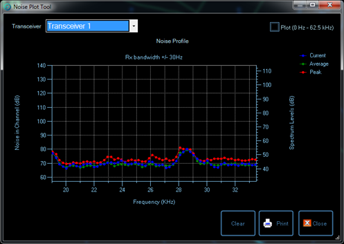
Within Ranger 2 is built in an FFT plotter. This should be the first tool of use when the 6G transceiver is deployed for the first time to ensure that there are no noise spikes within the operating frequency.
The information used in the following chart shows a transceiver with a very low noise floor of around 70dB for the first two-thirds of the usable frequency spectrum. For optimum performance, acoustic interrogation and reply frequencies at 24kHz and below should be used.
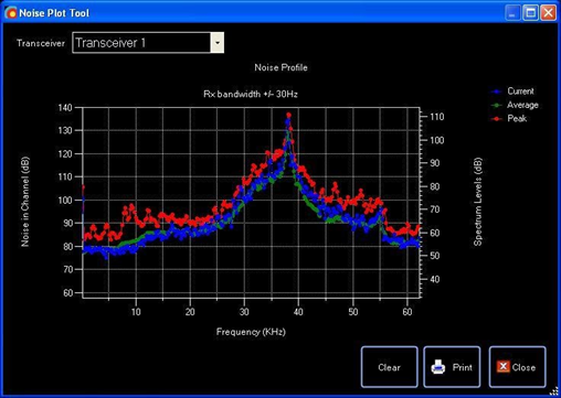
In some installations, there may be a raised noise floor and noise spikes to contend with, in the following example the acoustic noise floor is in the region of 10-20dB higher than our previous example, in addition to this there is a noise spike centred around the 38kHz mark spreading down to the 25kHz region.
In this example, lower frequency interrogation and reply addresses should be utilised, if operating at longer ranges it may be necessary to utilise WideBand 2+ for the associated processing gains in defeating the high noise floor.
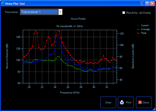
In the following noise plot, there is a significant noise source in the lower end of the frequency spectrum. The use of a higher operating frequency would be a big advantage in this situation.
The information provided above is a very brief introduction into the challenges and mitigation of noise sources. More information and in-depth training are available by contacting Sonardyne.
Looking for more content?
Find more product support in our Knowledgebase
Haven't found what you're looking for?
Then speak to one of our team for expert help

