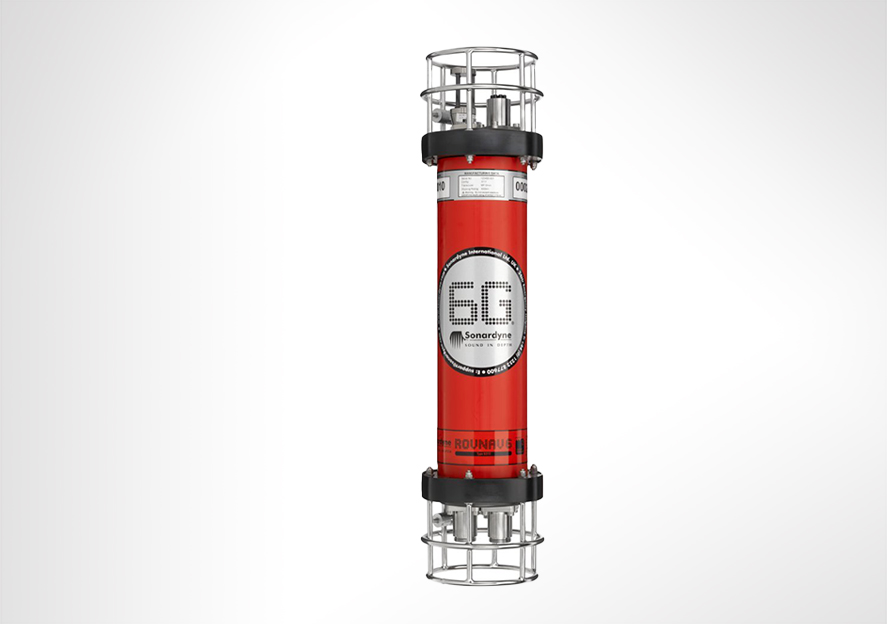
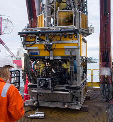
Engineered for Work-class ROVs
Overview
ROVNav 6 has been superseded by ROVNav 6+
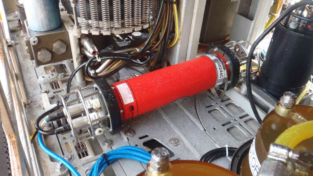
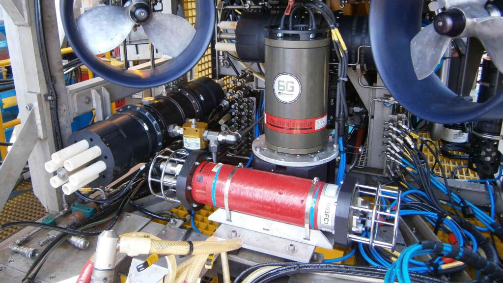
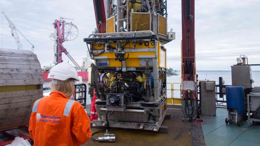
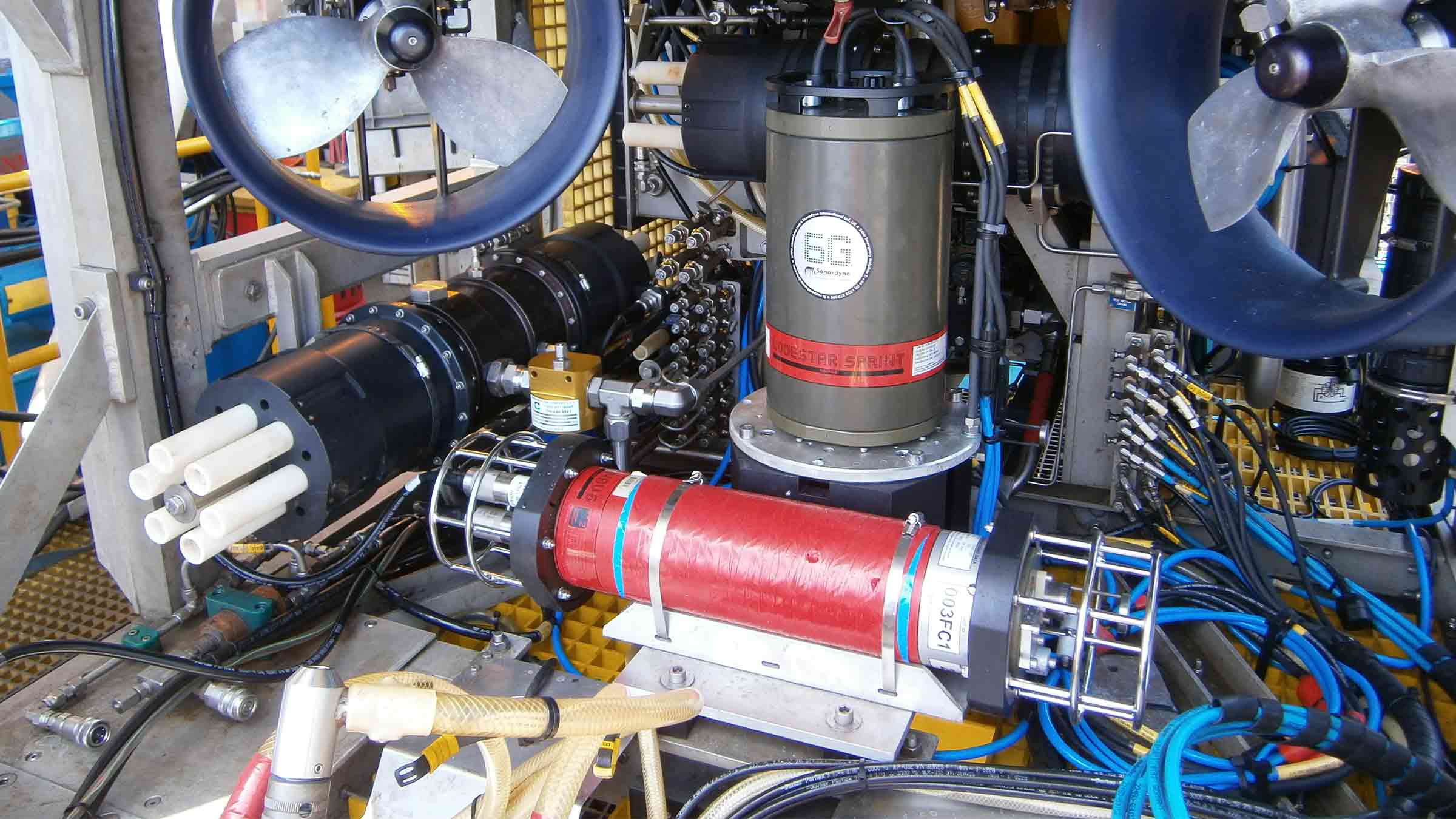
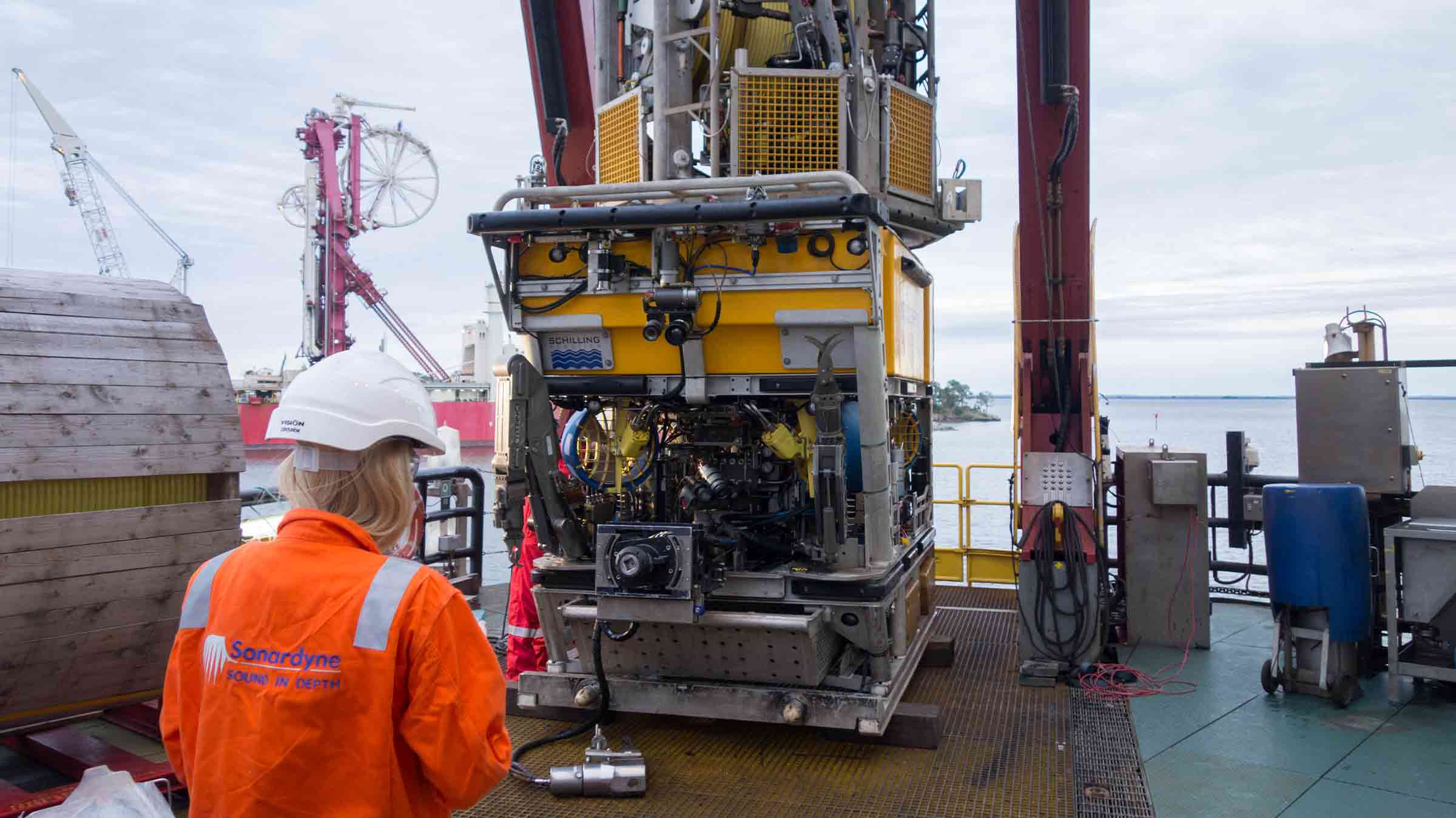
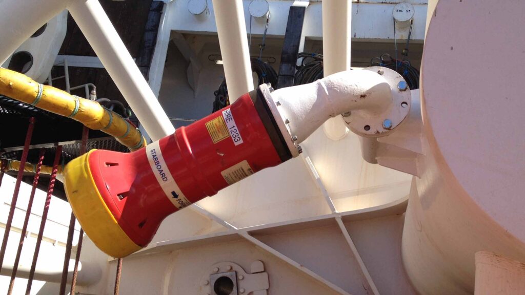
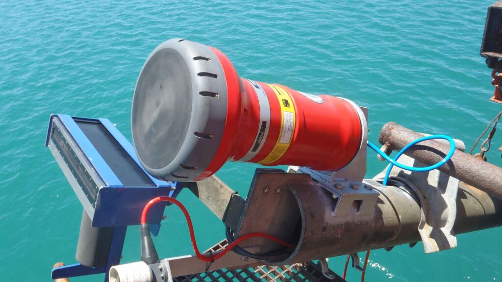
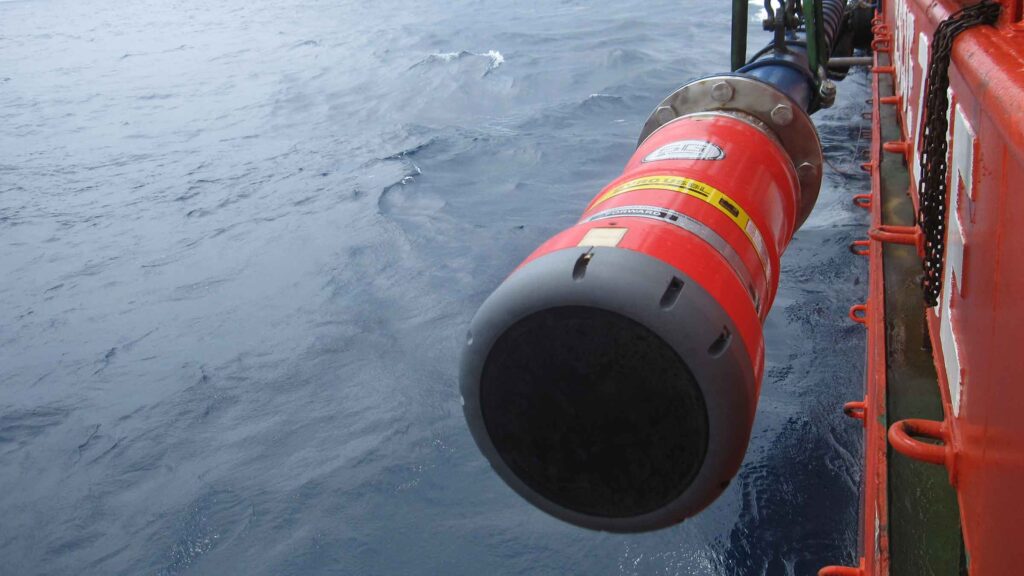
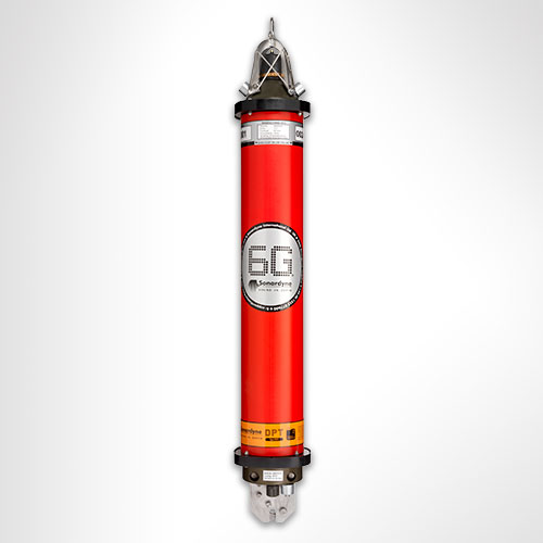
ROVNav 6 is a 6G Wideband 2 ranging LBL ROV Transceiver and telemetry transceiver specifically designed for installation on work class ROVs.
At a glance
- Use it with Fusion 6G
- Wideband 2 enabled
- High power, long range LBL transceiver
- 3,000, 5,000 or 7,000 m depth rated
- USBL mode for emergency ROV relocation
- Modem mode for harvesting data from Sonardyne sensors

Specifications table
| Feature | 8310-3161 | 8310-5261 | 8310-7261 | |
|---|---|---|---|---|
| Depth rating | 3,000 m | 5,000 m | 7,000 m | |
| Operating frequency | MF (20–34 kHz) | MF (20–34 kHz) | MF (20–34 kHz) | |
| Transducer beam shape | Omni-directional | Omni-directional | Omni-directional | |
| Transmit source level (dB re 1 µPa @ 1 m) | 187–196 dB (4 Levels) | 187–196 dB (4 Levels) | 187–196 dB (4 Levels) | |
| Tone Equivalent Energy (TEE) | 193–202 dB | 193–202 dB | 193–202 dB | |
| Receiver sensitivity (dB re 1 µPa) | 90–120 dB | 90–120 dB | 90–120 dB | |
| Range precision | Better than 15 mm | Better than 15 mm | Better than 15 mm | |
| Serial communications (software programmable) |
Primary port | RS232 or RS485 (half-duplex) | RS232 or RS485 (half-duplex) | RS232 or RS485 (half-duplex) |
| Secondary port | RS232 or RS485 (half-duplex) or SYNC IN | RS232 or RS485 (half-duplex) or SYNC IN | RS232 or RS485 (half-duplex) or SYNC IN | |
| Battery life Li-ion (listening) | 3 days | 3 days | 3 days | |
| Operating voltage | 24 or 48 V dc (±10%) | 24 or 48 V dc (±10%) | 24 or 48 V dc (±10%) | |
| External power | Active (listening) | <3 W typical (maximum 10 W when charging) | <3 W typical (maximum 10 W when charging) | <3 W typical (maximum 10 W when charging) |
| Peak (during transmission) | <80 W | <80 W | <80 W | |
| Serial communications connector | AGP (8-way female) |
AGP (8-way female) |
Subconn (8-way female) |
|
| Remote transducer connector | AGP (4-way male) | AGP (4-way male) | Burton (3-way male) | |
| Housing mechanical construction | Hard anodised aluminium 6082 |
Hard anodised aluminium 7075 |
Hard anodised aluminium 7075 |
|
| Remote transducer mechanical construction | Stainless steel 316 | Stainless steel 316 | Stainless steel 316 | |
| Dimensions (maximum) (length x diameter) | 768 x 200 mm | 768 x 200 mm | 768 x 200 mm | |
| Housing diameter | 134 mm | 134 mm | 140 mm | |
| Weight in air/water | Housing assembly | 14.3/5.3 kg | 14.7/5.7 kg | 15.5/6.0 kg |
| Transducer | 3.2/2.7 kg | 3.2/2.7 kg | 3.3/2.8 kg | |
| Cable (5 m) | 2.7/1.4 kg | 2.7/1.4 kg | 2.7/1.4 kg | |
| Sensors | ||||
| Temperature (±0.1°C) | Standard | Standard | Standard | |
| Strain gauge pressure sensor (±0.1%) | Standard | Standard | Standard | |
| High precision strain gauge (±0.01%) | Optional | Optional | Optional | |
| Inclinometer (tilt sensor) Range ±90°, accuracy: ±1° (vertical orientation) |
Standard | Standard | Standard | |
| Sound velocity sensor ±0.02 m/s accuracy under calibration conditions |
Standard | Standard | Standard |
Frequently asked questions
STP files
Datasheets
A SMART deepwater invention
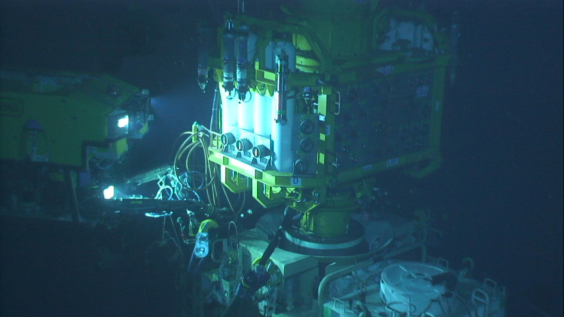
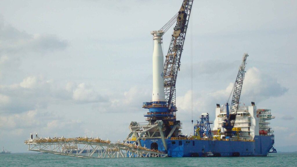
Operations in deepwater are a significant challenge requiring the latest generation of subsea equipment and installation techniques. While the majority of operations do go to plan, there are occasions when they don’t and an innovative approach to deepwater intervention is required.
The challenge
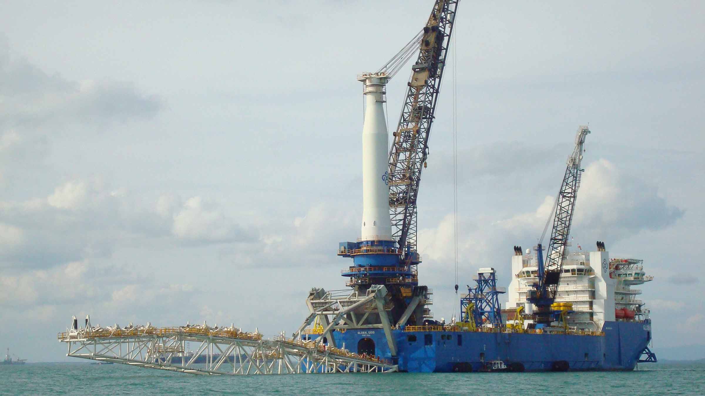
Houston headquartered engineering specialists Trendsetter Vulcan Offshore (TVO) were set just such a difficult deepwater intervention challenge. They were brought in to help an operator rectify a completed wellhead at a deepwater site that had suffered from misalignment. The wellhead, which was in more than 2,000 m water depth, had been bent and there were concerns other components might have been damaged.
TVO were tasked with finding a solution to bringing it back to a vertical position. This would allow intervention access to the well for remediation and abandonment operations, so it could be permanently sealed. A key challenge was to carry out this work extremely carefully and in a controlled manner, in order to prevent any further potential damage to the wellhead.
The solution
TVO came up with an innovative solution to the problem. It proposed a ring of six subsea tensioning systems, mounted on suction piles positioned in a ring on the seafloor around the wellhead. Each one would be connected via a rope to a Trendsetter-supplied lower riser package (LRP) installed onto the wellhead. By carefully tensioning the ropes, they would be able to then bring the wellhead back into an upright position.
To do this in a safe and controlled way, TVO required a monitoring system which would provide:
- Near real-time feedback of the tension data at each of six load pins installed on the LRP (one each for each of the six tensioners).
- Near real-time inclination data from the wellhead itself
Conventional deepwater intervention solutions
Traditionally, inclination data is acquired by visually checking subsea bullseye levels attached to a structure using a diver, or, in this water depth, a remotely operated vehicle (ROV). Similarly, visual displays on the tensioning systems would be the source of the tension data, also read using an ROV.
However, these techniques add a significant amount of time, given the 30-40 m radius of the circle of tensioning systems, even if, as was the plan, only two would need to be actively tensioned during the righting operation. Bullseyes can also be mis-read.
Another alternative option is to deploy battery powered accelerator and inclinometer measuring bottles, using an ROV. But these would have to be retrieved to the surface after each measurement, so would also mean a lengthy operation, potentially taking days.

Taking an alternative, SMART, real-time intervention approach
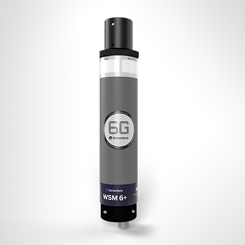
Instead, TVO proposed and successfully deployed a wireless, intelligent, digital underwater monitoring solution. This provided near real-time inclination and tension data to the operations team at the surface (around three minutes delay). It comprised of two of Sonardyne’s Subsea Monitoring, Analysis and Reporting Technology (SMART) and six Compatt 6 transponders.
The internal inertial measurement unit in each SMART was used to calculate pitch and roll data from two points either side of the LRP, allowing TVO to calculate the wellhead’s bend angle in the local coordinate frame.
This data was then transmitted acoustically, using the SMART’s internal modem, to the surface at three-minute intervals. The Compatt 6s were interfaced with the load cell shackles at each tensioner point on the LRP and transmitted the tension readings to the surface at less than one-minute updates.
Over
0
m
water depth
0
hour
critical righting operation
0
month
continuous monitoring campaign
The results
The righting operation took just three hours, using an ROV to tension the winches at two key tensioning units, one at a time. In comparison, using the alternative methods would have taken days. Throughout, the TVO team and the operator were able to view a constant near real-time visualization of the inclination of the wellhead and the tension that was being applied at each tensioning system. This was done via an internet-based dashboard developed by TVO, so that any member of the wider team, including the operator, from anywhere in the world could watch.
Making a SMART decision
“It was a very unique challenge. There were a lot of studies and approaches analysed within the customer group before making a decision to what the right approach was. They chose ours, using Sonardyne’s SMARTs and Compatt 6s, and it worked very well,” says TVO’s Kim Mittendorf.
“We really could control the two tensioners with the amount of tension we needed in near-real time. While the ROV was tensioning the winch, more than 2,000 m below us, we could see what direction the wellhead was moving in, how the pitch and roll angle changed.
“All the data was also live streamed to a website so that the customer, offshore and onshore, could monitor the operation in near-real time. This drove their decision making and gave them the comfort to continue with the operation as planned.”
Paving the way for a safe well abandonment
Following the righting of the wellhead, the tensioning and monitoring system was kept in place to allow safe intervention and final abandonment operations to be completed. During this phase, the data transmission rates were reduced to once every few hours.
For redundancy, two of the suction piles had relay Compatt 6s installed on them. This was due to a concern that direct line of sight to the transceiver from one or more of the Compatt 6s wouldn’t be possible.
In addition, the ROV had a ROVNav 6 transceiver, as another backup communications pathway. However, none of these were required as the LRP located SMARTs and the six Compatt 6s connected to the load pins were able to directly communicate with the topside transceiver.
Deepwater wireless well intervention success
The entire campaign proved to be a complete success. Thanks to TVO’s engineering and Sonardyne’s monitoring technologies, the operator was able to safely and efficiently decommission this challenging deepwater wellhead.
Initial skepticism from the operator in using a hydro-acoustic approach for data transmission was also overcome and through the success of the project, further confidence has been built into the technology for future applications.
Straight out of the box navigational enhancement for offshore out of straightness surveys
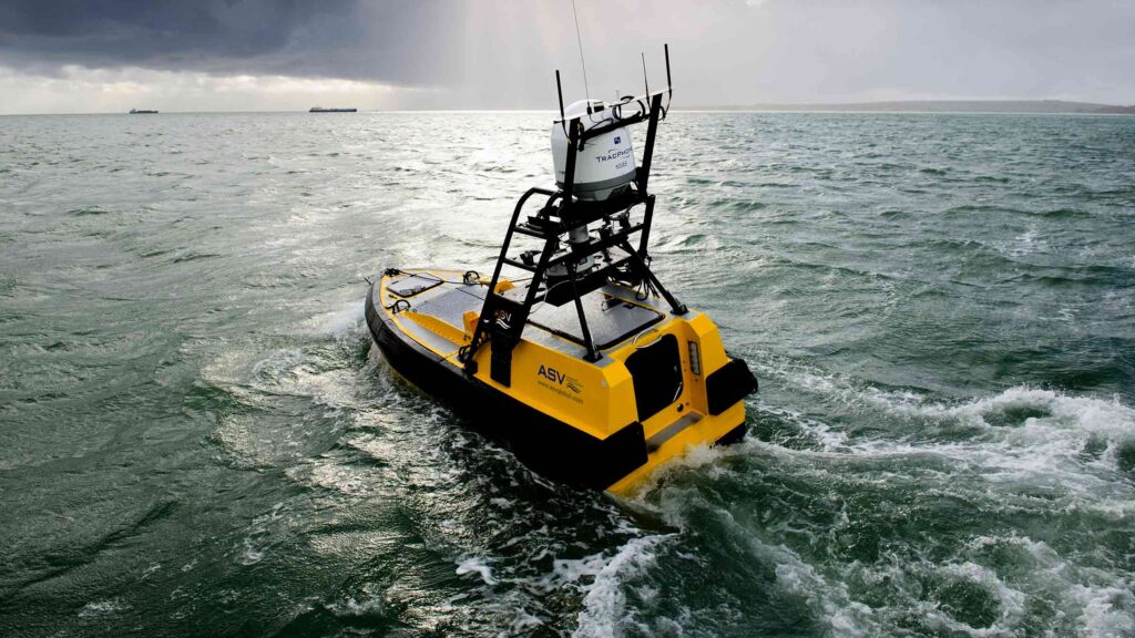
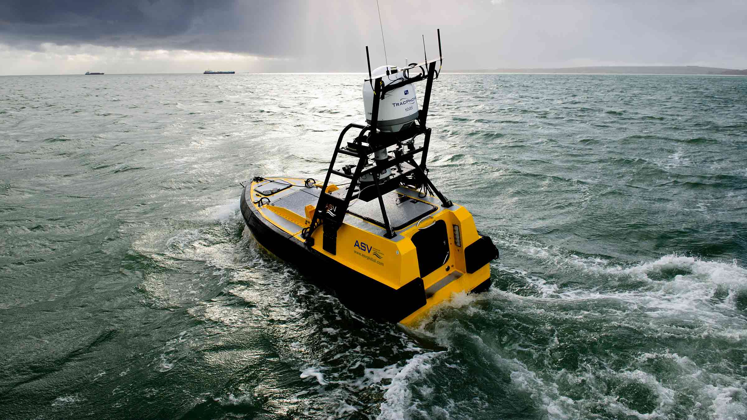
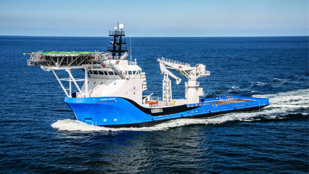
Fugro are already delivering safer, faster and more sustainable offshore operations – as you may have read in our previous case study about the Mini-Ranger 2 USBL system being used to support ROV operations from a USV. Working with us, Fugro are continuing their pioneering remote operations with their fleet of uncrewed surface vessels (USVs) deploying remotely operated vehicles (ROVs) – changing the game for offshore infrastructure surveys. Read on to see how our SPRINT-Nav Mini is being used to enhance multibeam echosounder (MBES) on Fugro’s remote operations, providing incredible results.
The challenge
Out of straightness (OOS) surveys are used for acquiring information about the vertical and horizontal configuration of offshore pipelines. They provide operators with information on the presence or otherwise of buckles and bending in a pipeline, which may be engineered or not, and require monitoring during the operational life of the pipeline or flowline asset.
Fugro have been conducting OOS surveys on pipelines for major energy companies in Australia for many years. These surveys were conducted using a Norbit WBMS Narrow Multibeam echo sounder mounted on a Fugro inspection class ROV deployed from Fugro’s 12m Blue Essence® USVs, Maali and Kwilena.
ROV missions along pipelines can be erratic and unreliable due to the distance between the transceiver (USV) and transponder (ROV) when using just USBL positioning. For Fugro’s OOS survey customers, highly accurate data is essential. This has led to their requirement for the highest accuracy navigation and imaging available to the small ROV.
Fugro set us the challenge to provide a navigation solution that would enable the customer requirements of high-quality data using a small ROV. We worked with Fugro to trial SPRINT-Nav Mini and demonstrate the capabilities of the system.
The solution
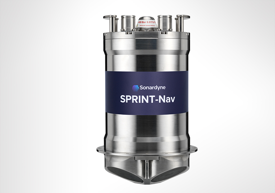
SPRINT-Nav Mini is the world’s smallest hybrid navigator, combining INS, DVL, AHRS and a pressure sensor in one factory calibrated unit. SPRINT-Nav Mini’s true north seeking gyrocompass means that it delivers reliable surface and subsea navigation. Adding this navigation capability to any marine robotic system allows users more control and turns their vehicles into far more accurate inspection and survey platforms.
With everything you need for navigation packed into a single low Size, Weight and Power (SWaP) package, SPRINT-Nav Mini is simple to integrate into any marine vehicle along with other payload sensors, like Fugro’s MBES. Its impressive precision of 0.05% of distance travelled accuracy on a typical survey alongside our revised heading, pitch and roll specification means that advanced mapping is now possible on smaller platforms deployed from USVs.
“SPRINT-Nav Mini is becoming increasingly vital for geophysical survey operations where SWaP is critical. Users need accurate and high output rate navigation streams for real-time compensation of imaging sensors.” Says John Houlder, INS Product Manager, Sonardyne, “SPRINT-Nav Mini provides robust real-time results that are improved even further once post-processed in our Janus software.”
After demonstrating SPRINT-Nav Mini’s capabilities, Fugro purchased the system and have been deploying it on their inspection ROV, which in turn is deployed from the Blue Essence® USV. With the Fugro team’s input we have been able to revise our specification for SPRINT-Nav Mini, improving its suitability for use with MBES on geophysical survey. These revisions include:
Pitch and Roll: 0.1 to 0.02° RMS
Heading: 0.15 to 0.1° RMS


The results
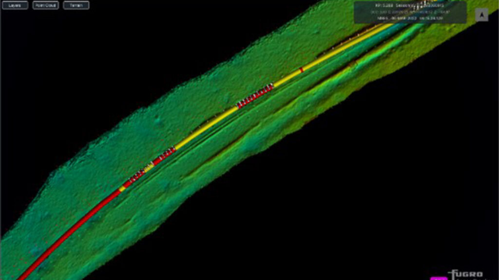
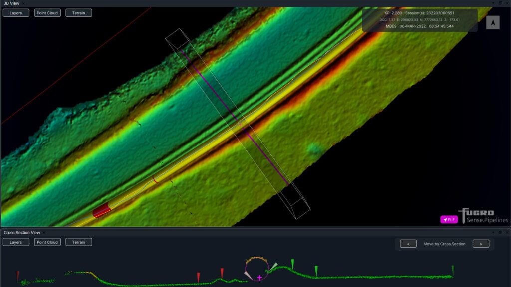
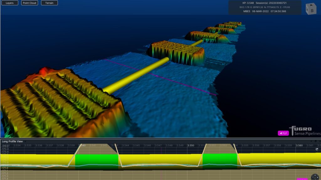
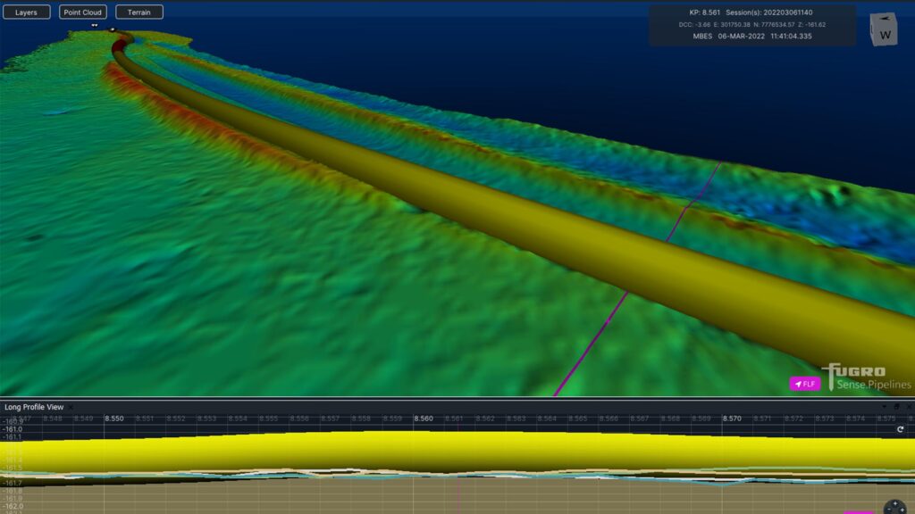
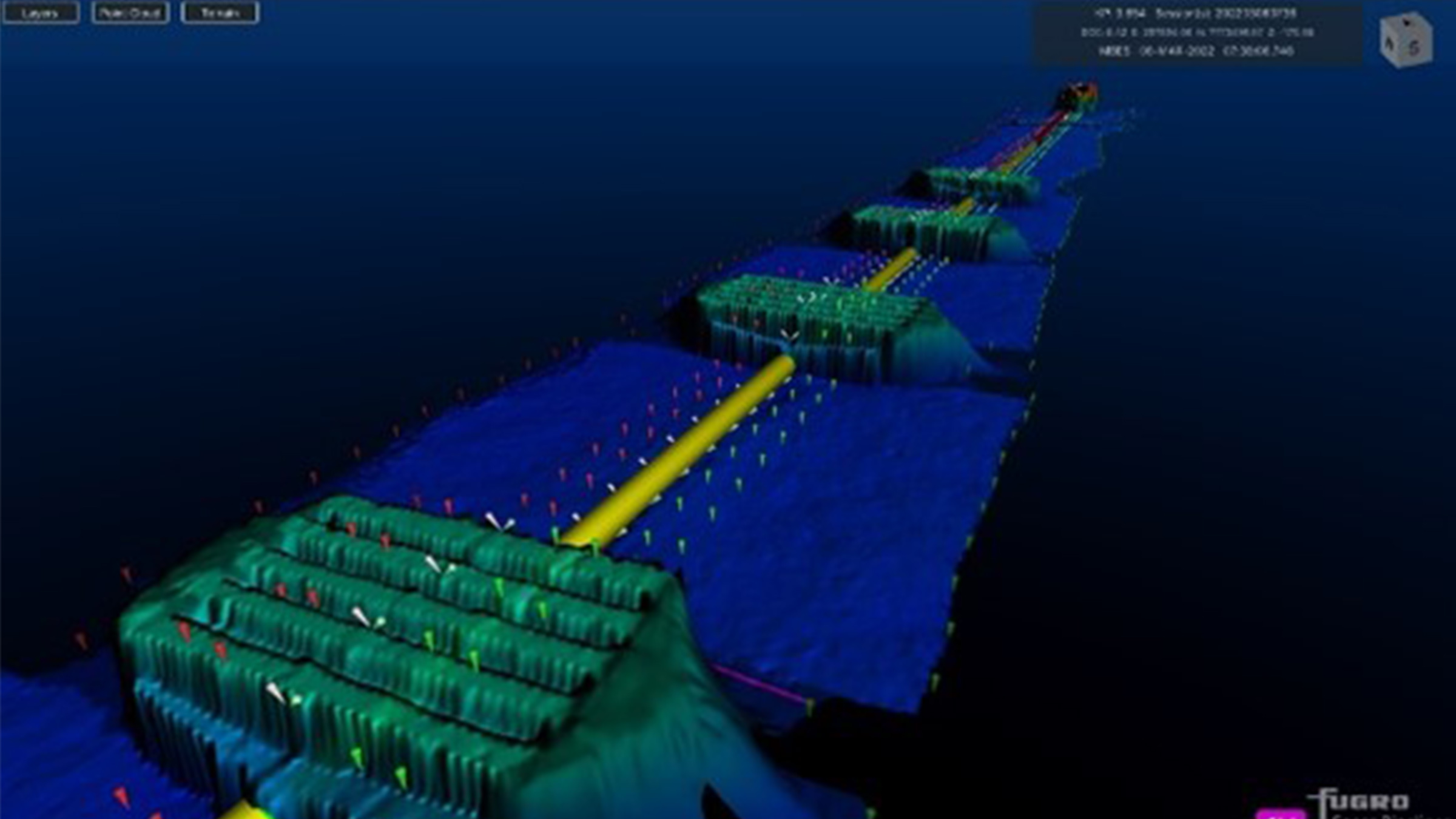
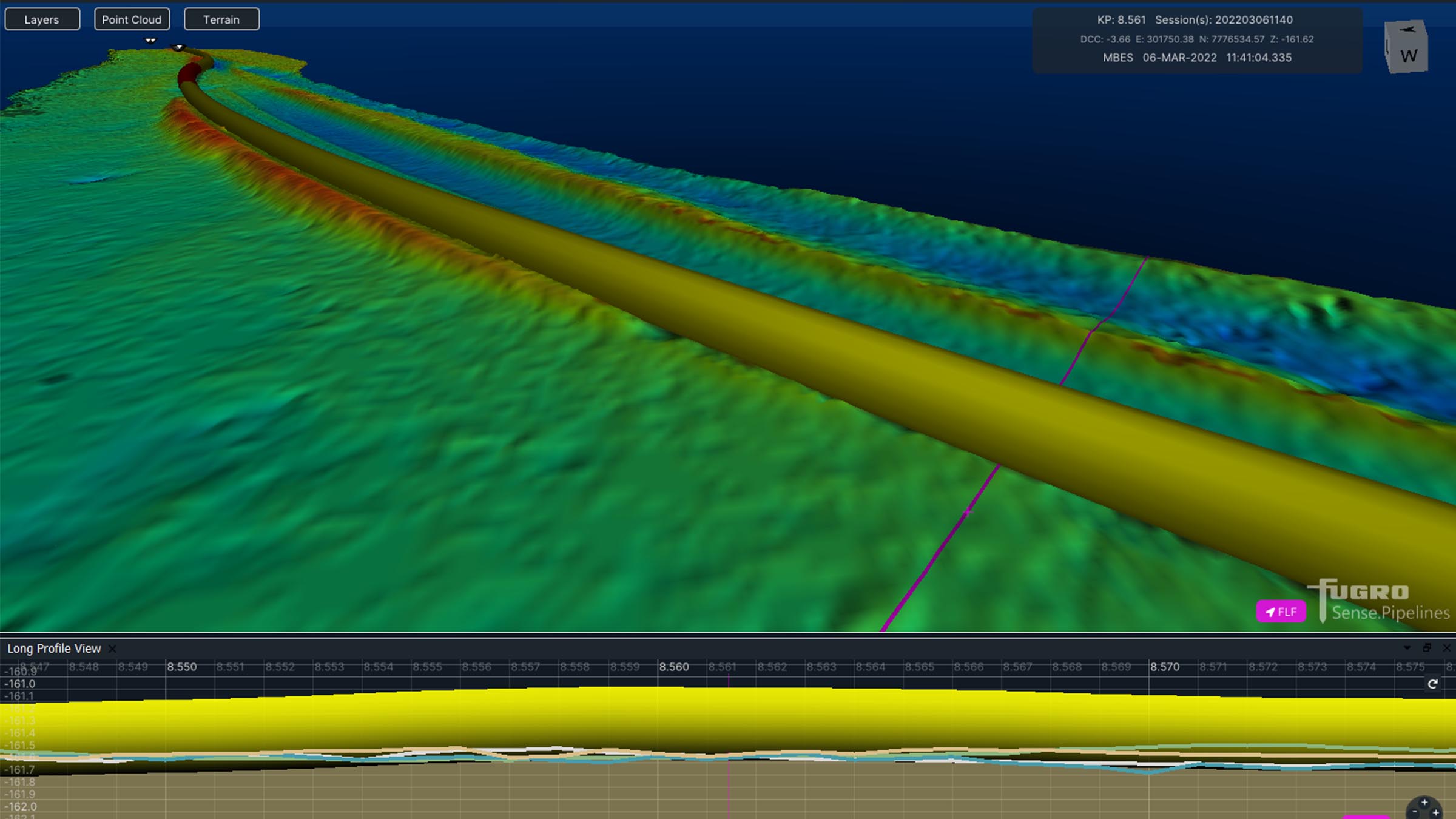
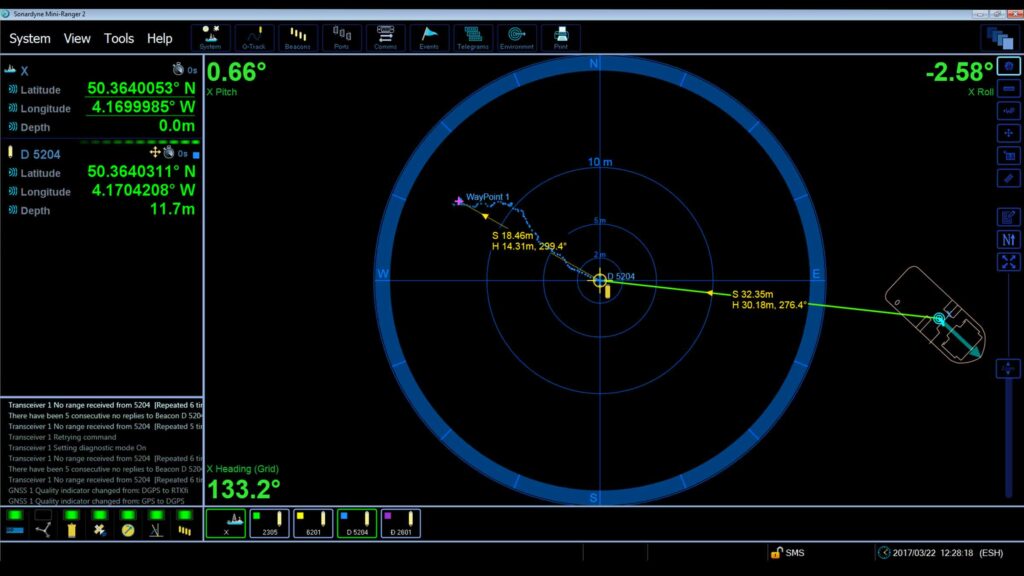
Fugro utilise SPRINT-Nav Mini data within the ROV command and control software, Starfix® navigation, including their Camblock Vision based augmented reality system, and for processing MBES data. In the case of MBES processing, they are also conducting pipeline OOS surveys to a maximum depth of 200 metres.
The images below show some example data Fugro has gathered with MBES positioned using SPRINT-Nav Mini and post processed with our Janus software. Janus is our quality control and INS post processing software. It allows quick and easy data editing, post-processing and data export. Find out more about Janus here
If your offshore operations are also reliant on fast, efficient and accurate data to keep your business competitive in an ever-changing marketplace, take a look at our full range of navigational products here.
Overview
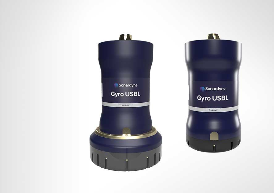
Gyro USBL: Precision and efficiency redefined
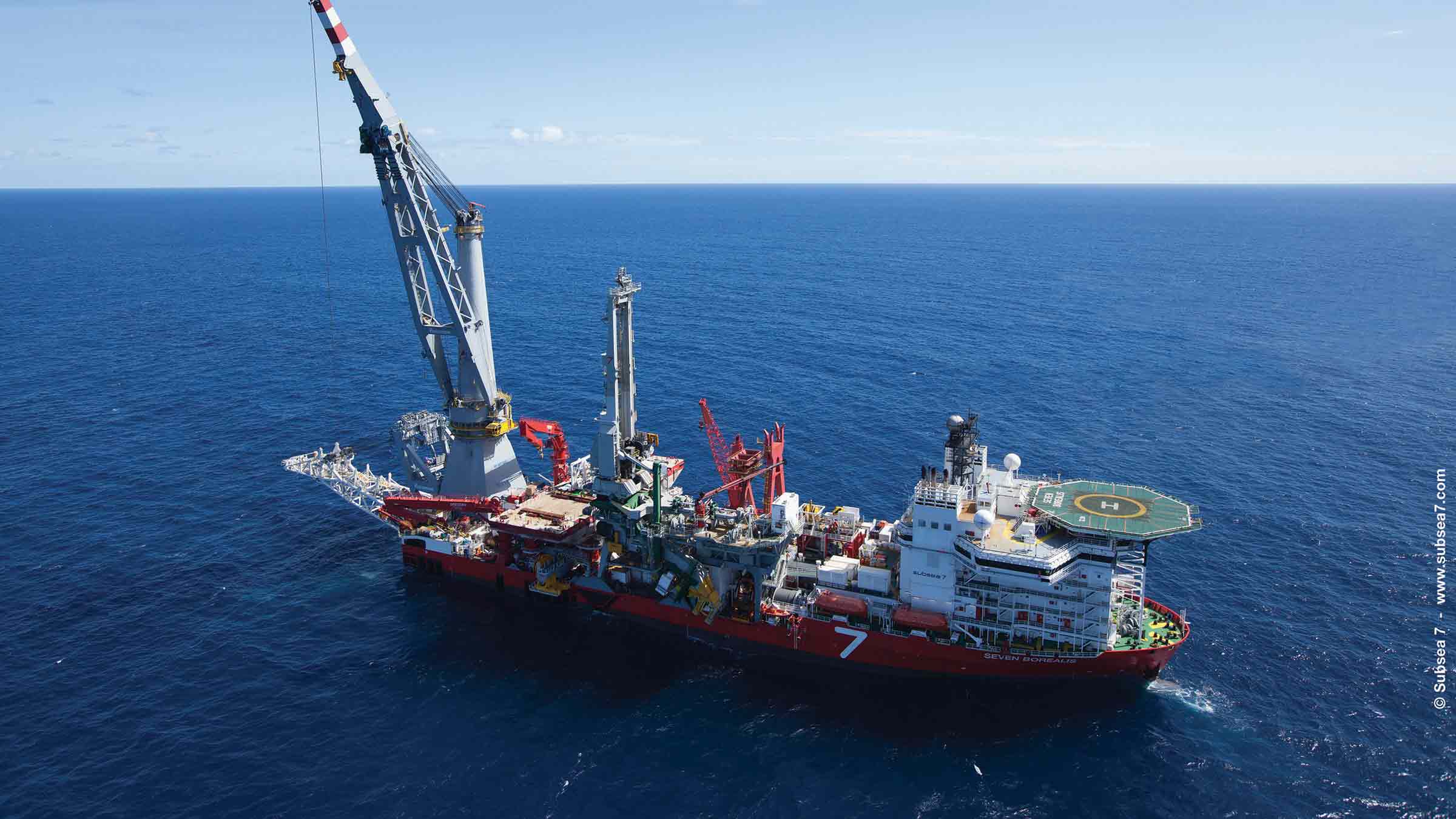
Introducing your next-generation Gyro USBL transceiver. Smaller, lighter, and packed with advanced features, it’s the ultimate solution for your precise subsea tracking operations. It works seamlessly with Ranger 2 to track the position of a subsea target from a USV, vessel of opportunity or from a pipelay vessel’s stinger over extreme ranges. Gyro USBL delivers the highest precision available and is now pre-calibrated direct from us, saving you precious operational time.
Accelerate your operations with our compact powerhouse
Key benefits
Saves you time and money: pre-calibrated for immediate deployment, eliminating setup delays.
Enhanced accuracy: delivers unparalleled precision through a combined acoustic transceiver and AHRS.
Versatility: ideal for a variety of applications, including subsea structure installation, pipeline positioning and USV operations.
Compact design: up to 20% shorter and 19 kg lighter than previous versions. It’s perfect for use in space-constrained environments such as on over-the-side poles and pipelay vessel stingers.
Optimised performance: seamless integration with Ranger 2 for superior tracking accuracy.
Experience the difference
Gyro USBL is more than just a tool – it's a game-changer. Whether you're in energy, defence, or science, our advanced technology will elevate your operations with:
- Faster deployment on vessels of opportunity or from a pipelay vessel’s stinger.
- Reliable and accurate target tracking for enhanced mission success.
- Expanded exploration capabilities with extended range and precision.
How it works
Combining our cutting-edge 6G acoustic transceiver with a high-performance AHRS, Gyro USBL eliminates the lever arm offsets, pole bending and ship flexing errors common in traditional USBL systems. Its compact, corrosion-resistant design ensures durability in any marine environment.
Upgrade your operations today
Discover how Gyro USBL can revolutionise your subsea projects. Contact us to learn more about this groundbreaking technology.


Performance
• Calibration free offering rapid mobilisation
• 7000 tested to better than 0.07% of slant range 1 DRMS
• Pitch and roll accuracy 0.01°
• Heave accuracy (real time) 5 cm or 5% (whichever the greater)
Design
• Works with Ranger 2 USBL and Marksman LUSBL systems
• 439 x 225 mm (5000 variant); 508 x 310 mm (7000 variant)
• 9 to 19 kg weight saving in air; 15 to 40% lighter than previous models
• Aluminium-bronze and plastic construction. ROHS compliant
• Calibration free offering rapid mobilisation
Acoustic and AHRS
• Heading accuracy 0.1° for ‘plus’ variant
• 7000 expected system slant range accuracy 1 DRMS (20 dB) 0.04°
• Pitch and roll accuracy 0.01°
• Heave accuracy (real time) 5 cm or 5% (whichever the greater
Ownership
• What’s in the box: Gyro USBL and manual
• Warranty: 1 year return to Sonardyne service centre
• ITAR Controlled: No
• UK Export License: required; US Export License: covered under de minimis
Specifications
| Feature | Gyro USBL 5000 Type 8084-0425 & Gyro USBL 5000+ Type 8084-0455 | Gyro USBL 7000 Type 8084-0427 & Gyro USBL 7000+ Type 8084-0457 | |
|---|---|---|---|
| Operational frequency | MF (20–34 kHz) | MF (20–34 kHz) | |
| Transceiver performance |
Operating range | Up to 7,000 m | Up to 7,000 m |
| Acoustic coverage | Up to ± 90° | Up to ±90° optimised for deepwater (dependant on frequency of operation) | |
| Range accuracy | Better than 15 mm | Better than 15 mm | |
| Expected system slant range accuracy 1 drms (20 dB) |
0.07% | 0.04% | |
| Transmit source level (dB re 1 µPa @ 1 m) | 200 dB | 200 dB | |
| Tone Equivalent Energy (TEE) | 206 dB | 206 dB | |
| Heading | Accuracy – Plus variant | 0.1° secant latitude | 0.1° secant latitude |
| Accuracy – Standard variant | 0.2° secant latitude | 0.2° secant latitude | |
| Settle time | <5 minutes in dynamic conditions | <5 minutes in dynamic conditions | |
| Pitch & roll (accuracy) | 0.01° | 0.01° | |
| Heave | Range | ±99 m | ±99 m |
| Accuracy (real time) | 5 cm or 5% (whichever the greater) | 5 cm or 5% (whichever the greater) | |
| Electrical | +48 V dc maximum 160 W |
+48 V dc maximum 160 W |
|
| Connector | AGP-2716 | AGP-2716 | |
| Communication | RS485, baud rate switchable, Ethernet 100 Mbps | RS485, baud rate switchable, Ethernet 100 Mbps | |
| Operating temperature | -5 to 40°C | -5 to 40°C | |
| Storage temperature | -20 to 45°C | -20 to 45°C | |
| Dimensions (length x diameter) | 400 x 225 mm | 469 x 310 mm | |
| Weight in air/water | 35.7/21.6 kg | 55.9/35.3 kg | |
| Note: The absolute accuracy of the system is dependent upon the beacon source level, vessel noise, water depth, mechanical rigidity of the transceiver deployment machine, SV knowledge and proper calibration of the total system using CASIUS |
Frequently asked questions
STP files
Software and firmware
Top tips
Datasheets
Manuals and quick start guides
Technical bulletin
Overview
Track anything, to any range
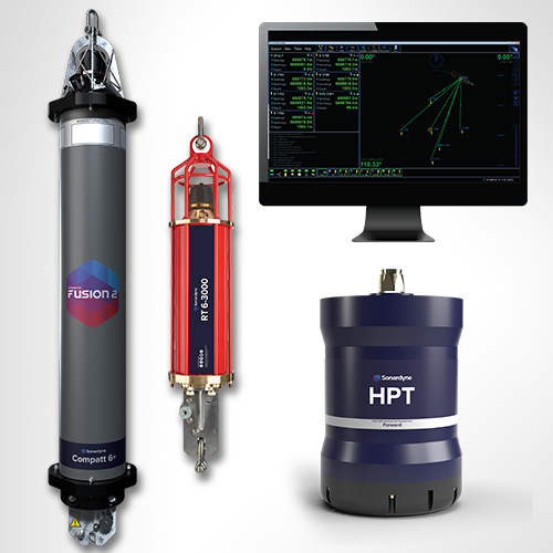
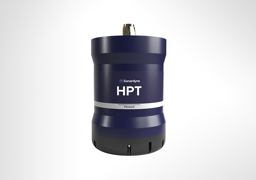
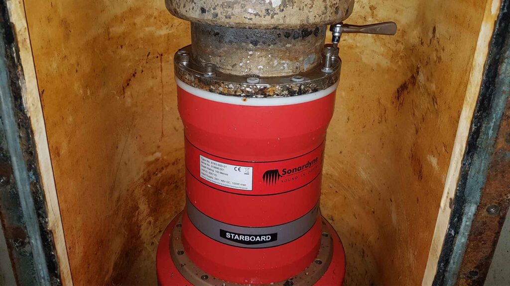
HPT 5000/7000s are acoustic and telemetry transceivers designed for use with Ranger 2 USBL and Marksman LUSBL systems. HPT 5000 enables targets to offer wide range of water depths to be tracked. HPT 7000 is optimised for noisy DP drilling and construction vessels and in deep water. Suitable for a wide range of applications from pipeline positioning and riser monitoring to subsea structure installation as well as tracking and communications.
Overview
When it comes to USBL and LUSBL transceivers, one model does not fit all situations and vessels. For Ranger 2 and Marksman installations, our High Performance Transceiver (HPT) is available two primary configurations.
HPT 5000
HPT 5000 offers full hemispherical acoustic coverage so it’s a popular choice for tracking multiple targets (ROVs, AUVs, towfish, seafloor sensors) over a wide range of depths and elevations. The unit is also suitable for dynamic positioning reference on survey, research and offshore support vessels.
HPT 7000
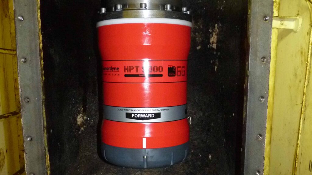
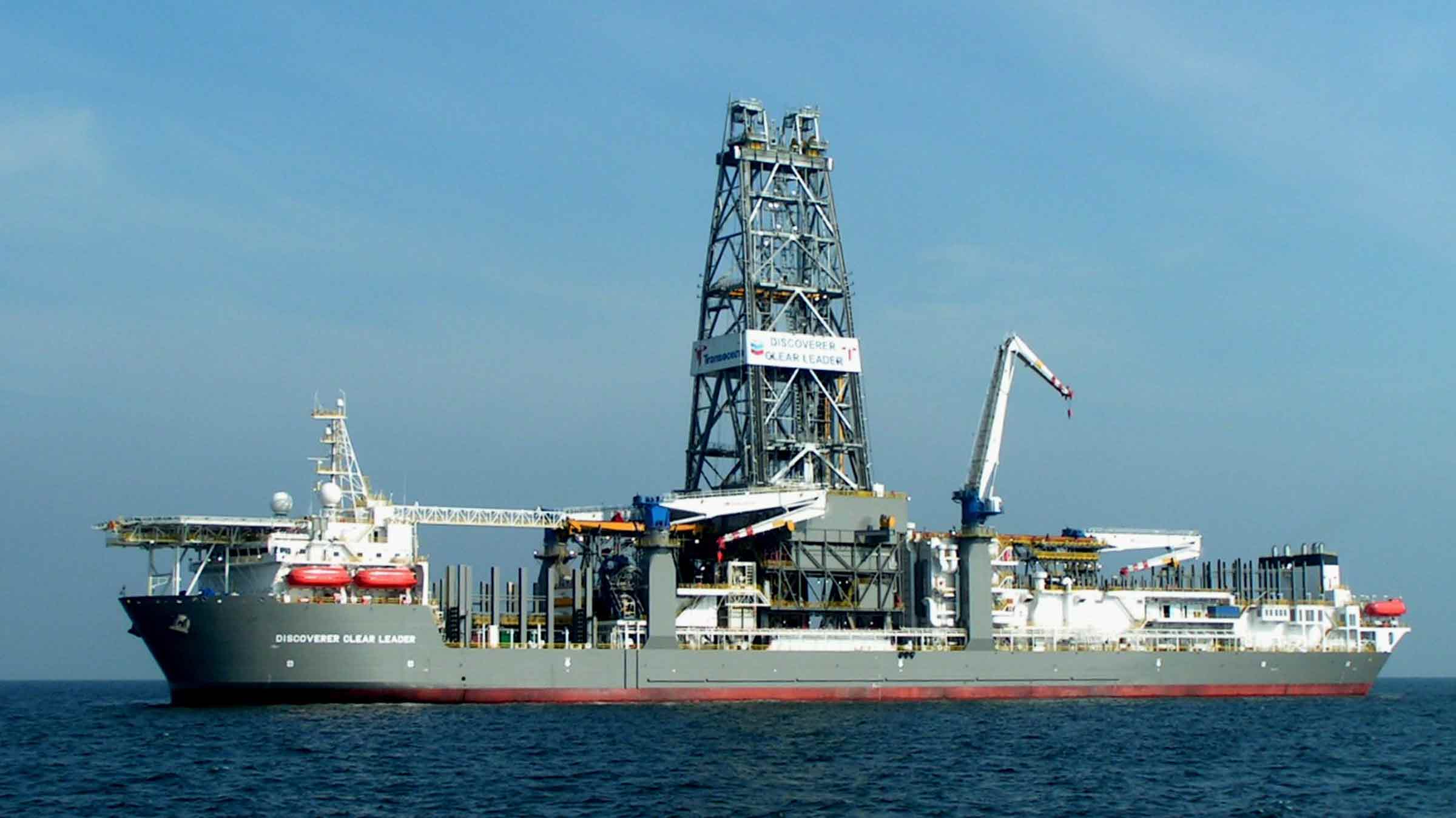
HPT 7000 is engineered for ultra-deepwater operations, tracking targets far below (rather than to the side) of a vessel, and also high vessel noise operating environments, as those typically encountered on DP drilling and construction where aeration from thrusters is liable to cause signal interference.
Both models of transceiver fully support 6G LBL operations using Fusion 2 LBL software. They are also highly capable acoustic communications modems, able to interrogate, command and recover data payloads from deployed Sonardyne instruments including AMTs and Fetch. Supporting telemetry rates of up to 9,000 bps minimises the time a vessel has to wait on location to recover data, as well as supporting LBL operations.
HPT 5000/7000s are also available in Gyro USBL configurations offering calibration-free installation and use.
At a glance
- Use with Ranger 2 USBL and Marksman LUSBL systems
- Can also be used to communicate and harvest data from Sonardyne sensors
- Hemispherical (HPT 5000) or directional (HPT 7000) arrays to suit your vessel and application
- Can be deployed other-the-side, through-tube or through-hull
- Suitable for new-build vessels or USBL/LUBL upgrade for your existing vessel
All HPTs are built on our 6G technology platform with multi-element processing to enable transponders to be positioned more precisely, more quickly and more robustly due to improvements in signal processing algorithms and array design.
Functionality such as ‘Discovery Mode’ enables vessels equipped with Ranger 2 and Marksman to enter an offshore area and automatically detect previously deployed transponders (including their configured address and channel), making simultaneous operations using shared seabed arrays possible.
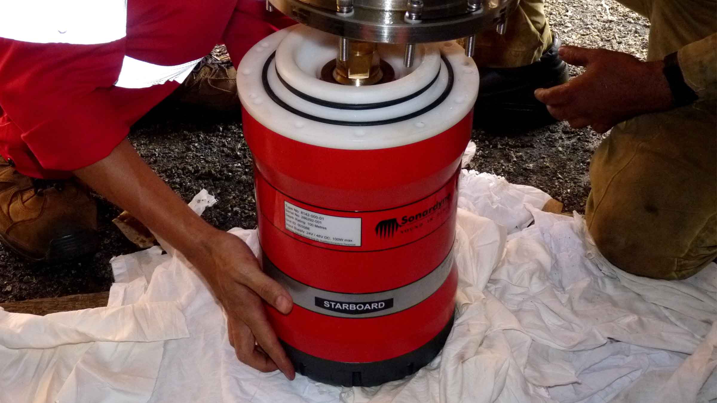
Manufactured in aluminium-bronze, HPTs are intended to be fitted temporarily or permanently to a vessel’s through-hull or over-the-side pole. HPT 5000s (including Gyro USBL 5000s) have also been fitted to large USVs for uncrewed missions controlled from over-the-horizon.
For specialist applications, inverted USBL, LMF frequency and extreme depth range HPT transceivers are also available. Please get in contact to discuss your requirements.


Ranger 2 in action
Optimising shallow water positioning for combined magnetometer and hydrographic surveys
Read moreAutonomous robots prepare to storm the ocean depths
Autonomous robots prepare to storm the ocean depths
A new world of multi-robot ocean exploration
Read moreSpecifications table
level, vessel noise, water depth, mechanical rigidity of the transceiver deployment machine, SV knowledge and proper calibration of
the total system using CASIUS.
| Feature | Type 8142-001 | Type 8142-002 (deepwater optimised unit) | |
|---|---|---|---|
| Operational frequency | MF (20–34 kHz) | MF (20–34 kHz) | |
| Transceiver performance |
Operating range | Up to 7,000 m | Up to 7,000 m |
| Acoustic coverage | Up to ± 90° | Up to ± 90º Optimised for deep water (depending on frequency of operation) |
|
| Range precision | Better than 15 mm | Better than 15 mm | |
| Positioning repeatability | All transceivers tested to better than 0.1% of slant range 1 Drms | All transceivers tested to better than 0.07% of slant range 1 Drms | |
| Transmit source level (dB re 1 µPa @ 1 m) | 200 dB | 200 dB | |
| Tone Equivalent Energy (TEE) | 206 dB (13 JA) | 206 dB (13 JA) | |
| Electrical | 48 V dc (±10%), Typical 15 W, Max 120 W |
48 V dc (±10%), Typical 15 W, Max 120 W |
|
| Communication | RS485, baud rate switchable, ethernet 100 Mbps |
RS485, baud rate switchable, ethernet 100 Mbps |
|
| Operating temperature | -5 to 40°C | -5 to 40°C | |
| Storage temperature | -20 to 45°C | -20 to 45°C | |
| Mechanical construction | Aluminium bronze | Aluminium bronze | |
| Dimensions (length x diameter) | 322 x 225 mm | 391 x 310 mm | |
| Weight in air/water | 26.7/15.3 kg | 46.9/29.0 kg | |
| Options | Tilted array adaptor | Tilted array adaptor |
Frequently asked questions
How to clean a transceiver array face
How to enter Transceiver & Lodestar Offsets for Optimised USBL
HPT Deployment Tests
Has anyone ever installed an echosounder and Ranger 2 USBL transceiver directly beside each other? Would this work?
How do USBLs work?
Does the HPT’s main connector need any maintenance?
When to use Depth Aiding
What acoustic address should I use for my USBL transponder
How to interface Ranger 2 into a 3rd party survey system
STP files
Software and firmware
Software and control hardware
Datasheets
Did you know?
Both HPT 5000 and 7000 are available in Gyro USBL configurations
Overview
Guiding your subsea vehicles
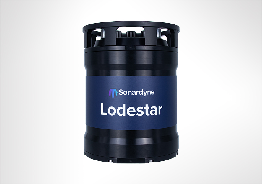
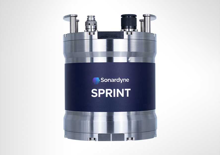
Lodestar is a high-quality Attitude and Heading Reference System (AHRS) designed for subsea AUV/UUV guidance applications. It is also available in different performance levels depending on your needs. Lodestar is a solid-state Attitude and Heading Reference System (AHRS) highly optimised for cost, size, weight, and power (C-SWaP). Suitable for tracking and communications with AUVs, USVs, ROVs and XLUUVs.
Overview
The instrument is a turn-key solution comprised of carefully selected high grade and highly reliable inertial sensors integrated into in-house designed inertial measurement unit (IMU).
The selected inertial sensors are the standard for commercial aviation with a proven 20+ year track record. These sensors have a highly desirable characteristic being insensitive to vibration, temperature changes and having very limited initial errors. The result is a system which is highly suitable for the marine environment where performance, robustness and data integrity need to be available from initialisation, even during the harshest conditions.
Lodestar requires no external aiding and settles robustly in dynamic conditions in less than five minutes. On-board data storage and backup battery functionality ensures continued operation and eliminates the risk of data loss even if communications or external power are lost. Power-pass through to external aiding sensors is supported to ease integration requiring only a single cable for comms and power.
If a full INS solution is required, Lodestar can easily be field upgraded to a SPRINT system (apart from Lodestar 200). This makes the Lodestar a flexible and future-proof solution for both ROV guidance and survey applications.
Lodestar has a proven track record spanning more than 10 years in the field in diverse applications from ROV guidance and autopilot to demanding survey applications. The instrument is available in 4,000 and 6,000 metre depth ratings with a variety of connector options and configurations.
At a glance
- Designed to aid subsea vehicle guidance: AUVs, ROVs and UUVs
- Uses high quality Honeywell gyro and accelerometers
- Sensors available in three performance levels: 200, 300 and 500
- Fast settling time so you can get straight to work
- Integrated DVL option available; Lodestar-Nav
- Factory upgradeable to SPRINT INS
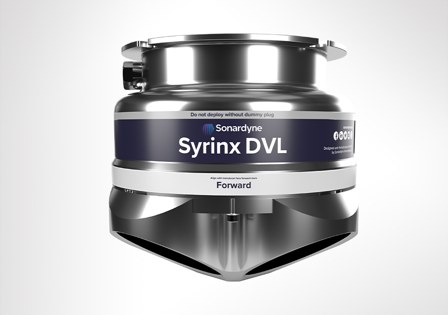
Lodestar-Nav 200
Lodestar-Nav 200 provides all-in-one navigation solution for subsea vehicles by combining a Lodestar 200 AHRS with our Syrinx Doppler Velocity Log (DVL) and a high accuracy pressure sensor in a single housing. This saves cost, payload space and the complexity of integrating and operating separate sensors from different vendors.
Lodestar-Nav is pre-calibrated providing the ROV pilots with a robust and reliable solution, even in the most challenging operational scenarios, without needing to worry about sensor offsets.
Syrinx DVL inside that provides a large altitude range and high precision at all altitudes; this combines the best of 300 and 1200 kHz DVLs. Each DVL transducer is fitted with a full depth rated water block to ensure protection of the internal components and easy replacement if damaged.
Lodestar-Nav can be interfaced via a single connection and/or the DVL can be interfaced separately depending on requirements. Continuous on-board data storage supports post-mission diagnostics and post-processing.


Size
Measuring just 260 mm tall, the 4,000 m rated titanium housing allows easy fitment to any subsea vehicle. 6,000 m housing option.
Long life sensors
Lodestars and SPRINTs use Honeywell-supplied RLGs and inertial sensors with 400,000 MTFB, which have been proven in over 20 years in commercial aircraft.
Connectivity
Most Lodestars can be upgraded to SPRINT in the field as your requirements grow so there’s no need to remove and re-install a different instrument.
Specifications
| Feature | Lodestar 300 | Lodestar 500 | |
|---|---|---|---|
| Depth rating | 4,000 / 6,000 m | 4,000 / 6,000 m | |
| Performance | |||
| Heading | 0.2° | 0.1° | |
| AHRS settle time | <5 minutes in dynamic conditions | <5 minutes in dynamic conditions | |
| Roll and pitch | 0.01° | 0.01° | |
| Power | |||
| Power requirement | 20–50 V dc, 15 W nominal, 35 W maximum | 20–50 V dc, 15 W nominal, 35 W maximum | |
| Power pass through | 3 x for external aiding sensors (up to 3A per sensor) | 3 x for external aiding sensors (up to 3A per sensor) | |
| Back up battery type/life | Li-ion/5 minutes | Li-ion/5 minutes | |
| Data/Comms | |||
| Data storage | 8 GB internal memory | 8 GB internal memory | |
| Serial ports/protocol | 4x RS232 or RS485 | 4x RS232 or RS485 | |
| Other ports | 1x Ethernet, 4 triggers | 1x Ethernet, 4 triggers | |
| Output rate | Up to 100 Hz | Up to 100 Hz | |
| Output telegrams | Industry standard AHRS/INS telegrams including acceleration and rotation rates | Industry standard AHRS/INS telegrams including acceleration and rotation rates | |
| Mechanical | |||
| Connectors | 4x Seacon / Seanet, 1x Seacon / Seanet | 4x Seacon / Seanet, 1x Seacon / Seanet | |
| Mechanical construction | Titanium | Titanium | |
| Dimensions (diameter x height) |
4,000 m (Seacon) | 205 x 260 mm | 205 x 260 mm |
| 6,000 m (Seacon) | 205 x 280 mm | 205 x 280 mm | |
| 4,000 m (Seanet) | 205 x 250 mm | 205 x 250 mm | |
| Weight in air/water | 4,000 m | 18.5/11.5 kg | 18.5/11.5 kg |
| 6,000 m | 22/14 kg | 22/14 kg | |
| Environmental | |||
| Operating temperature | -20 to +55°C | -20 to +55°C | |
| Storage temperature | -20 to +60°C | -20 to +60°C | |
| Shock rating | 22 g, 11 ms half sine | 22 g, 11 ms half sine |
Frequently asked questions
SPRINT, SPRINT-Nav, Lodestar and Lodestar-Nav troubleshooting
How to connect to the Lodestar within a Gyro USBL via an NSH
How to enter Transceiver & Lodestar Offsets for Optimised USBL
What cables do I need for my Lodestar?
How do I mate and calibrate a DVL to my Lodestar?
Can I power my subsea instruments with Lodestar or SPRINT?
How do I mate and calibrate a SPRINT or Lodestar to my Syrinx DVL?
What’s the difference between FOG and RLG?
STP files
Software and firmware
Software and control hardware
Manuals and quick start guides
Technical bulletin
Did you know?
Lodestar is highly optimised for cost, size, weight and power (C-SWaP)
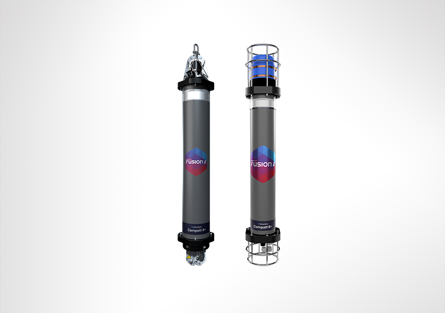
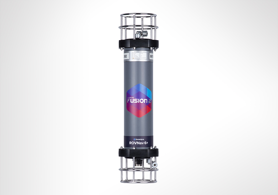
Overview
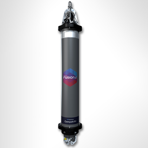
Designed for Work-class ROVs
ROVNav 6+ (plus) is a Wideband 3 and Wideband 2 ranging LBL and telemetry transceiver specifically designed for installation on work-class ROVs. ROVNav 6+ is suitable for pipeline positioning, seabed deformation monitoring and metrology.
Overview
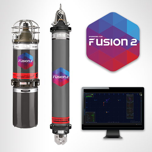
ROVNav 6+ uses our new Wideband 3 signal technology, which is key to unlocking the benefits of your Fusion 2 LBL system.
It allows, for the first time, sensor telemetry data (e.g. pressure, depth or temperature) from a seabed or structure deployed Compatt 6+ to be embedded within navigation (ranging) data. This change has a big impact on operations such as structure installation, as breaks in tracking to get sensor reading updates at vital moments are now a thing of the past.
Its compatibility with Wideband 3 and Wideband 2 telemetry commands, and support of high power Wideband 2 ranging protocols, proven for their accuracy and robustness, means the ROVNav 6+ offers improved range and acoustic performance in challenging conditions such as on noisy vehicles or in multipath environments.
At a glance
- High power, long range LBL transceiver for ROVs
- Wideband 3-enabled supporting embedded sensor data with ranging data
- Optimised for Fusion 2 and compatible with Fusion 1
- 3,000, 5,000 or 7,000 m depth rated options
- USBL mode for emergency ROV relocation
- Modem mode for harvesting data from Sonardyne logging sensors; Fetch, AMT…
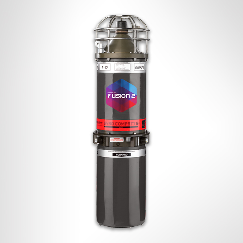
ROVNav 6+ is also a fully functional USBL responder or transponder, compatible with Wideband 2 USBL systems and HPR400. The internal li-ion rechargeable battery pack also enables emergency transponder mode, so if the umbilical and therefore power is cut to the ROV it can still be located by USBL.
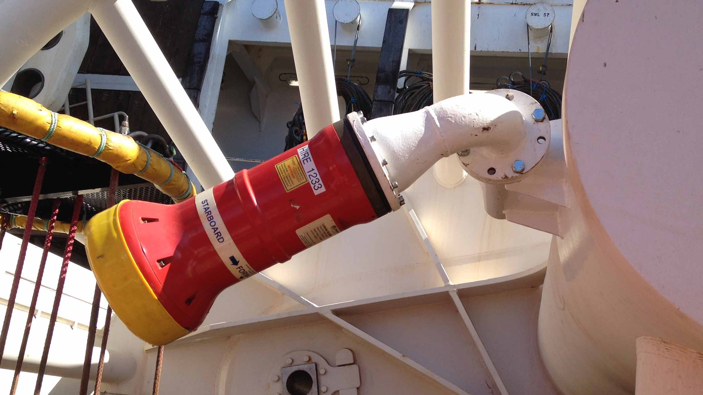
The omni-directional remote MF transducer makes installation on an ROV easy. ROVNav 6+ is designed to be rugged and relatively lightweight and utilises robust underwater connectors. ROVNav 6+ supports a range of internal sensors including: strain gauge pressure, PRT temperature and MEMS based inclinometer.
ROVNav 6+ is also fully compatible with our modem and logging equipment such as AMT and Fetch products, allowing it to be used to retrieve data or configure logging regimes. It supports all of our Wideband 2 and Wideband 3 spread spectrum acoustic communication; 100 to 9,000 bps data rates can be selected depending on the environment.
Sensor options include a Digiquartz pressure sensor, precision inclinometer and altimeter interface. This provides a fully featured ROV manipulator deployable tool/sensor pack for a range of different applications including metrology, bathy survey and structure deployment operations, without the requirement for any additional interfacing on the ROV.
Specifications table
| Feature | 8340-3161 | 8340-5261 | 8340-7261 |
|---|---|---|---|
| Depth Rating | 3,000 m | 5,000 m | 7,000 m |
| Operating Frequency | MF (20–34 kHz) | MF (20–34 kHz) | MF (20–34 kHz) |
| Transducer Beam Shape | Omni-directional | Omni-directional | Omni-directional |
| Transmit Source Level (dB re 1 µPa @ 1 m) | 187–196 dB (4 levels) | 187–196 dB (4 levels) | 187–196 dB (4 levels) |
| Range Precision | Better than 15 mm | Better than 15 mm | Better than 15 mm |
| Serial Communications | RS232 or RS485 (half-duplex) | RS232 or RS485 (half-duplex) | RS232 or RS485 (half-duplex) |
| Battery Life Li-ion (Listening) | 3 days | 3 days | 3 days |
| Operating Voltage | 24 or 48 V dc (±10%) | 24 or 48 V dc (±10%) | 24 or 48 V dc (±10%) |
| Serial Communications Connector | Subconn (8-way female) | Subconn (8-way female) | Subconn (8-way female) |
| Remote Transducer Connector | Burton (3-way male) | Burton (3-way male) | Burton (3-way male) |
| Housing Mechanical Construction | Hard anodised aluminium 6082 | Hard anodised aluminium 7075 | Hard anodised aluminium 7075 |
| Remote Transducer Mechanical Construction | Stainless steel 316 | Stainless steel 316 | Stainless steel 316 |
| Dimensions (Maximum) (Length x Diameter) | 768 x 200 mm | 768 x 200 mm | 768 x 200 mm |
| Weight in Air/Water | 14.3/5.3 kg | 14.7/5.7 kg | 15.5/6.0 kg |
Frequently asked questions
If I’m using Fusion 2, can I choose to use Wideband 2 or Wideband 3 telemetry?
Can ROVNav 6+ be used with standard Compatt 6s?
Will my ROVNav 6 work with Fusion 2?
Do I need to upgrade to Compatt 6+ and ROVNav 6+?
Where should I install my ROVNav 6+ transducer?
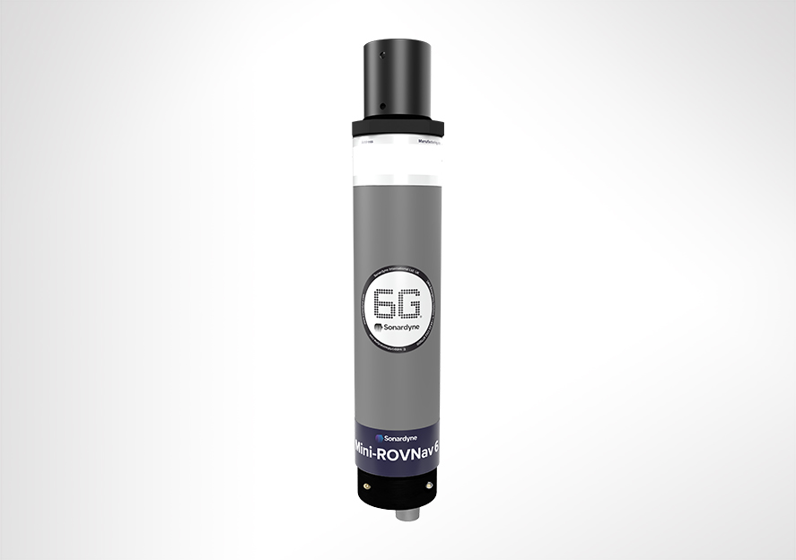
What are the differences between a ROVNav 6+ and Mini ROVNav 6+ ?
How to QC a Sound Velocity (SV) in Fusion 2
How far can my Compatt 6+ be above the seabed?
How do I perform an LBL calibration in Fusion 2?
STP files
Software and firmware
Transponders
Datasheets
Manuals and quick start guides
Technical bulletin
Did you know?
ROVNav 6+ is compatible with Fusion 1 and can be depth rated up to 7,000 m