What is a PIES?
A Pressure Inverted Echo Sounder (PIES) is a subsea monitoring instrument, widely used across the ocean science industry, for measuring the average sound speed through a column of water.
How does a PIES work?
A PIES works by transmitting a sound pulse from the instrument on the seabed to the sea surface and back, measuring the time it takes for the pulse to travel the round trip. It will also measure the depth of the water column using a high accuracy pressure sensor; the pressure sensor measures the pressure of the water above the PIES, which is directly proportional to the depth of the water. By combining the depth and travel time, the average sound speed in the water column can be calculated. PIES instruments are typically deployed on the seabed from a ship or remotely operated vehicle. They can be configured to operate for periods of several months or up to 5 years.
An example of how Pressure Inverted Echo Sounders have been used in ocean science studies is work done by the University of Rhode Island researching the Gulf of Mexico Loop Current and the loop current eddies it regularly sheds. Their research study included a major deployment of PIES. For the purpose of this study, they modified the design of our PIES to integrate a current meter, making it a CPIES, allowing them to harvest near-seabed current data. Combining this data from the array of PIES and near-bottom current meters with historic water profile data was then used to calculate currents throughout the full water column over an extended area, which for this project totalled over 50,000 sq km. The long-term objective of this study is to improve the forecasts of the Loop Current to increase the safety of operations in the Gulf. Find out more here
There are a wide range of oceanographic applications for a PIES: monitoring ocean currents and circulation patterns, measuring salinity, studying the effects of climate change on the ocean, measuring the density of the water column (which is important for understanding ocean dynamics). Furthermore, PIES can also be used within commercial applications, such as: offshore oil and gas exploration and production, marine engineering and construction, and cable and pipeline routing.
Pressure Inverted Echo Sounders are available at either 3,000 or 6,000 m depth rating and can be deployed for over 5 years.
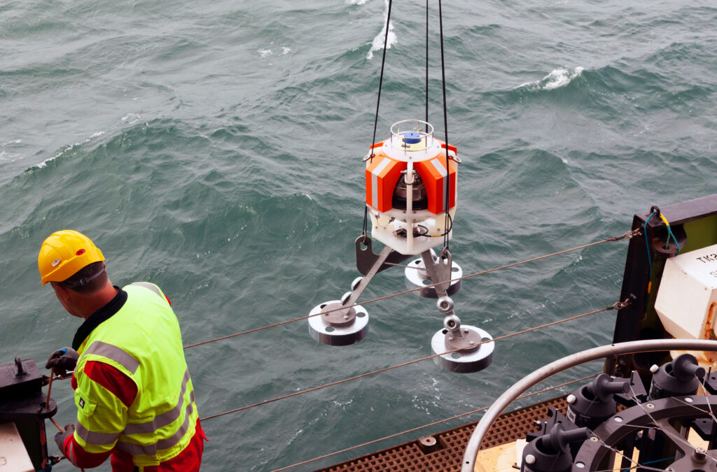
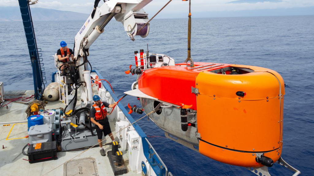
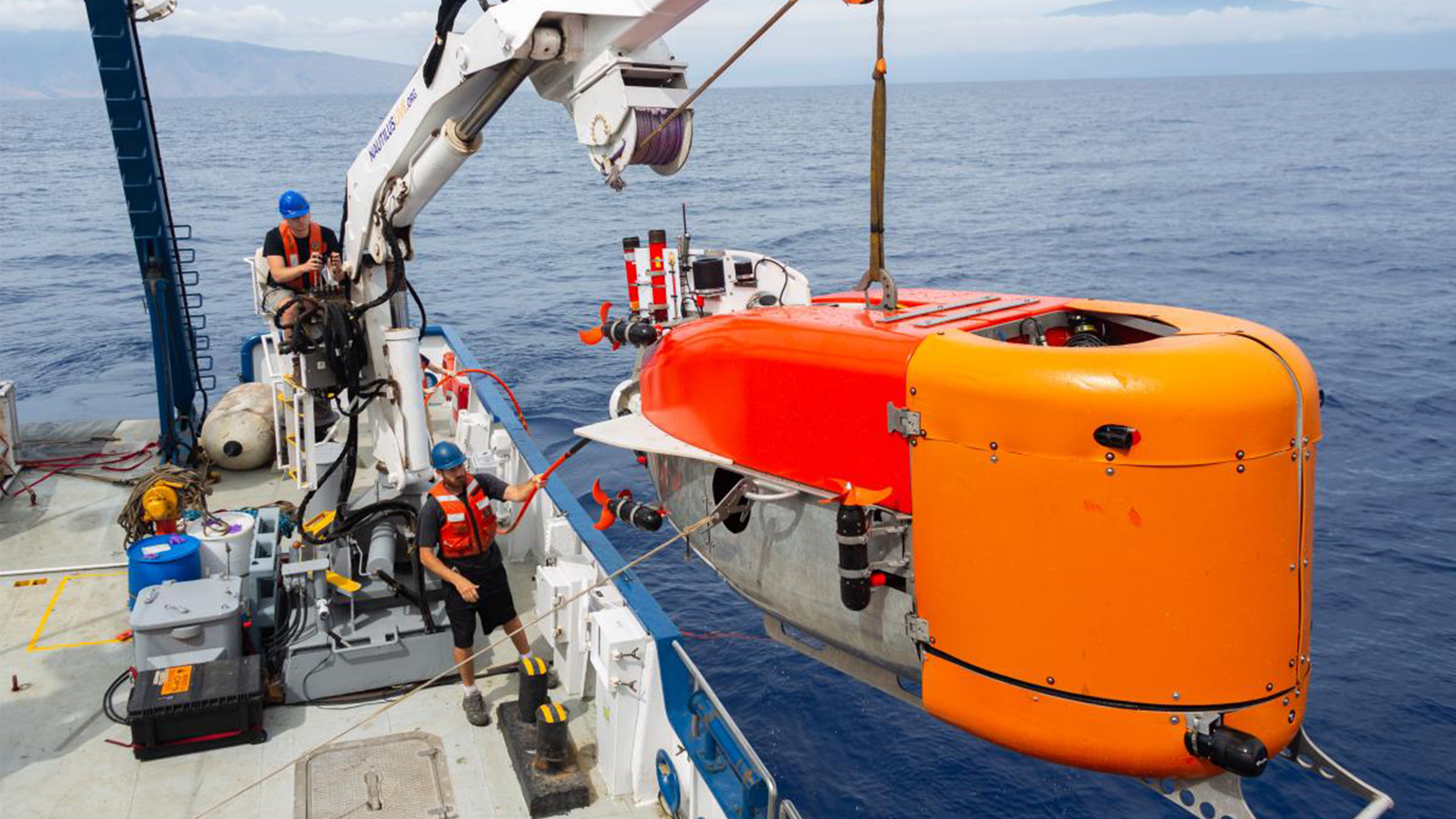
PIES being deployed over the side of a vessel
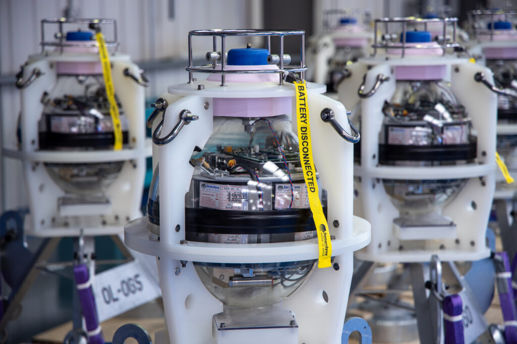
PIES tested and ready to leave production
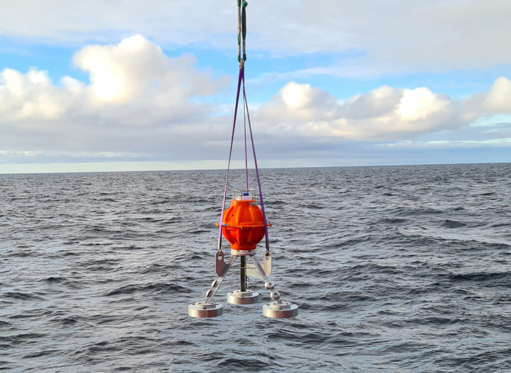
PIES being deployed
Contact [email protected] for more information.
The following system setup is recommended prior to starting a CASIUS calibration.
- Confirm all software and firmware versions are up to date.
- Test the HPT operation by running the HPT tests.
- Use Sonardyne 6G beacons. Complete a pre-deployment 6G Terminal Lite test to confirm operation and store the report.
- Set the Sonardyne 6G beacon address to 27xx or 28xx (xx = 01 – 14).
- All external instrument inputs should be input direct to the NSH or ESH for the CASIUS calibration. Confirm the inputs prior to and during the CASIUS calibration if there are any dropouts stop, investigate, and resolve. You may need to re-run the calibration leg.
- The GNSS accuracy recommendation is RTK Float.
- The minimum input rate are VRU 10 Hz and Gyro 5 Hz.
- Confirm (DIMCON) the GNSS antenna and HPT offsets to the CRP. Make sure these offsets are input directly to Ranger 2 for the CASIUS calibration.
- Set the “Operating Range” in the Environmental page.
- Set the Geodesy.
- If possible, use a Sound Speed profile for the local operational area.
- Always use the 1/3 water depth even when using run lines or Clover leaf patterns.
- Run a Noise test prior the CASIUS calibration on the headings that will be used.
- Use the Acoustic Link Status tool to optimise the beacon acoustics. Check the beacon positions during the CASIUS calibration and if there are multiple missed or jump in position stop, investigate, and resolve. You may need to re-run the collection leg.
Contact [email protected] for more information.
SPRINT-Nav Mini describes performance in two ways: typical survey and distance from origin. All positioning error is quoted to CEP50 without USBL or GPS.
Typical survey
Typical survey describes how the SPRINT-Nav should perform when doing a “typical survey” mission. This would be best described as a “lawnmower” or “grid” survey, as would be typical in a Side Scan Sonar or Multibeam Echo Sounder data collection mission. This would involve:
- Approximately 1 km in one direction
- 180-degree turn
- Approximately 1 km in another direction
- 180-degree turn
- and then repeating the above
Distance from origin
Distance from origin describes how the SPRINT-Nav should perform when travelling from one point to another in a straight line. Typically used for an AUV or Vessel when leaving port and travelling to a location.
Typical survey values are always lower (higher performance) because many of the common bias (not error) which are associated with Hybrid-Navigation systems (SPRINT-Nav/SPRINT-Nav mini) tend to cancel out when a vehicle travels on an opposite heading over a similar area of seabed. Examples of these bias that could cancel out are described below:
Sound velocity bias
If a sound velocity sensor is reading incorrectly say for example 1% wrong, the bias will apply as a scale factor which will cause the distance measured by the DVL to be either shorter or longer than the true distance. When the vehicle turns the bias will measure the same wrong distance, causing the error to cancel out.
Heading bias
If the heading is reading higher or lower than truth two things may happen:
- On a reciprocal line the bias may cancel out, i.e. one side of truth in one direction, the other side in the other direction.
- On a reciprocal line the bias or error in the heading value may be lessened because the system has rotated and thus has more observability, causing it to settle nearer to truth.
DVL aided
When the DVL is tracking the seabed successfully, in the web UI this would display an “OK” message on the main page.
Guidance and Navigator
Guidance is a variant of SPRINT-Nav mini which does not function as a full INS, meaning it does not calculate position. These are typically used on simple ROVs.
Navigator is the main and biggest selling variant of SPRINT-Nav mini which calculated and provides a full INS position. This is the variant for which the 0.05/0.3% error values are stated.
Contact [email protected] for more information.
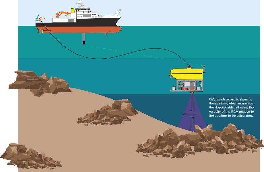
What is a DVL?
A Doppler Velocity Logger (DVL) is an instrument that measures the velocity (speed and direction) of an underwater vehicle relative to the sea bottom. They can be used in a broad range of applications, including underwater navigation, surveying and oceanographic research.
How does a DVL work?
A DVL works by using the Doppler effect, which is the change in frequency of a wave due to the relative motion between the source of the wave and the observer. DVLs transmit a series of sound waves towards the sea bottom and then measure the frequency shift of the reflected echoes. The Doppler shift is directly proportional to the relative velocity between the vehicle and sea bottom.
Typically, a DVL has 4 transducers which emit sound beams in 4 different directions, by comparing the Doppler shift echoes from each transducer, the DVL can calculate the vehicle’s speed and direction of travel. As the vehicle moves, the frequency of the sound waves is shifted due to the Doppler effect, the DVL then measures the amount of this shift and calculates the velocity of the vehicle relative to the sea floor. By combining the measurements from all 4 transducers, the DVL can calculate the velocity of the vehicle in 3 dimensions (forward/backward, left/right and up/down).
A DVL is typically mounted to the bottom of an underwater vehicle such as an ROV (remotely operated vehicle) or an AUV (autonomous underwater vehicle).
For a stand-alone DVL, the Syrinx DVL is available in two frequencies; 400kHz for longer ranges, or 600kHz for high resolution. For a combined INS and DVL solution, we also offer a family of hybrid navigators; the SPRINT-Nav integrates a full Syrinx DVL, pressure sensor and a SPRINT acoustically aided INS, this system can support complex survey and navigation missions using ROVs (Remotely Operated Vehicle) and AUVs (Autonomous Underwater Vehicle). Another member of our family of hybrid navigators is the SPRINT-Nav Mini which has 3 ROV instruments in one; a 500kHz Syrinx -derived DVL, hybrid AHRS and depth sensor, this is pre-calibrated making it quick to mobilise.
-
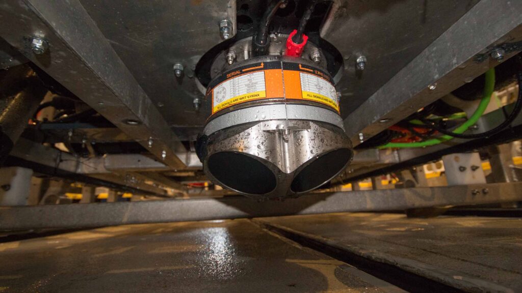
- DVL mounted to the bottom of an ROV
-
- DVLs measure movement relative to the seafloor
-
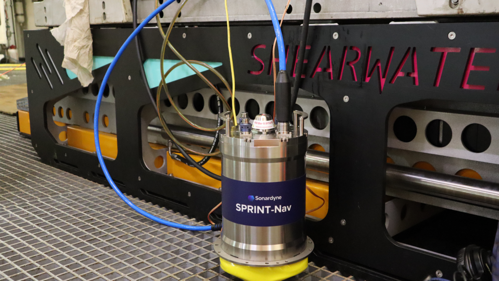
- SPRINT-Nav being installed on a work class ROV
More specific information about our family of DVLs can be found here.
Contact [email protected] for more information.
What is an Acoustic Release?
An acoustic release is an oceanographic device for the deployment and subsequent recovery of instrumentation from the sea floor, in which recovery is triggered remotely by an acoustic command signal.
How does an Acoustic Release work?
An acoustic release consists of three main components: a transducer, electronic control unit and a release mechanism. The transducer is a device which converts acoustic signals into electrical signals and vice versa and the electronic control unit is responsible for processing the acoustic signals and commanding the release mechanism.
There are three phases of operation when using an acoustic release: the deployment phase, the operation phase and the recovery phase. In the first phase (deployment), the instrument package is dropped to the sea floor. The package includes the anchor weight (allows the assembly to sink and remain on the sea floor), acoustic release device (receives remote commands), instrument or payload and a floatation device.
In the second phase, the instrument package is on the sea floor, collecting data or performing other tasks, this phase can last from minutes to several years. The final phase is the recovery phase, where an acoustic command is sent from a control station on a boat or an ROV; the acoustic release verifies the command, then triggers a mechanism that drops the anchor weight. The floatation device then brings the rest of the instrument package back to the surface for recovery.
An acoustic release has a variety of applications, including:
- To recover instrumented mooring lines
- Recovery of subsea structures
- Deployment of payloads onto the seabed such as for marine construction or cable laying
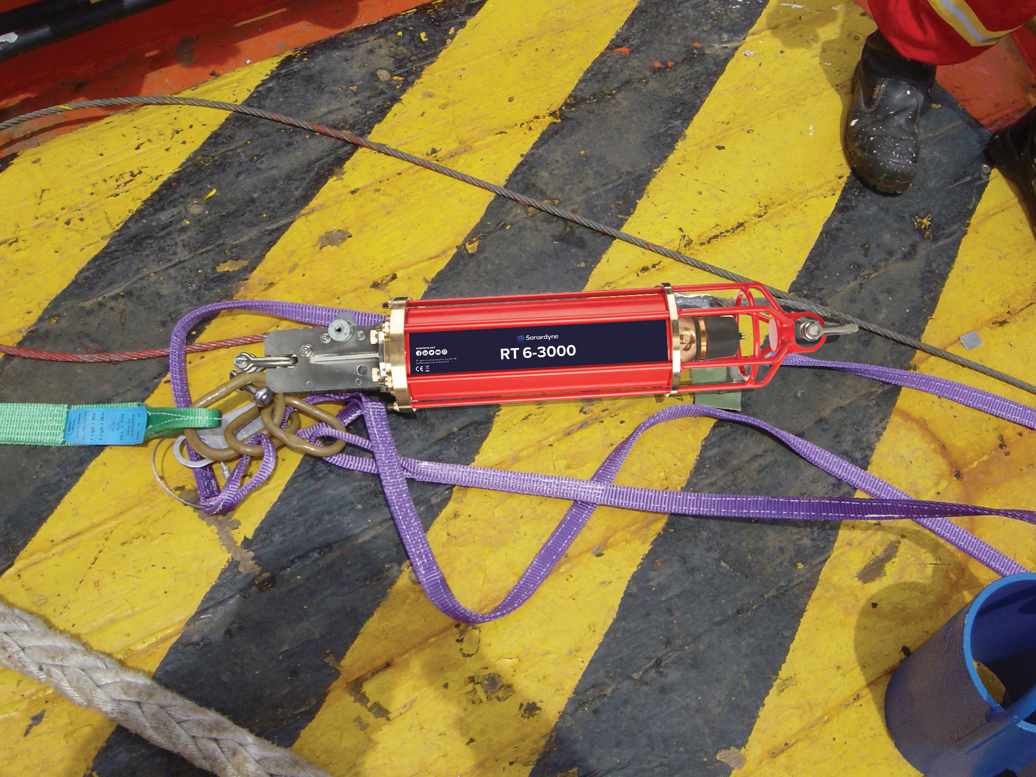
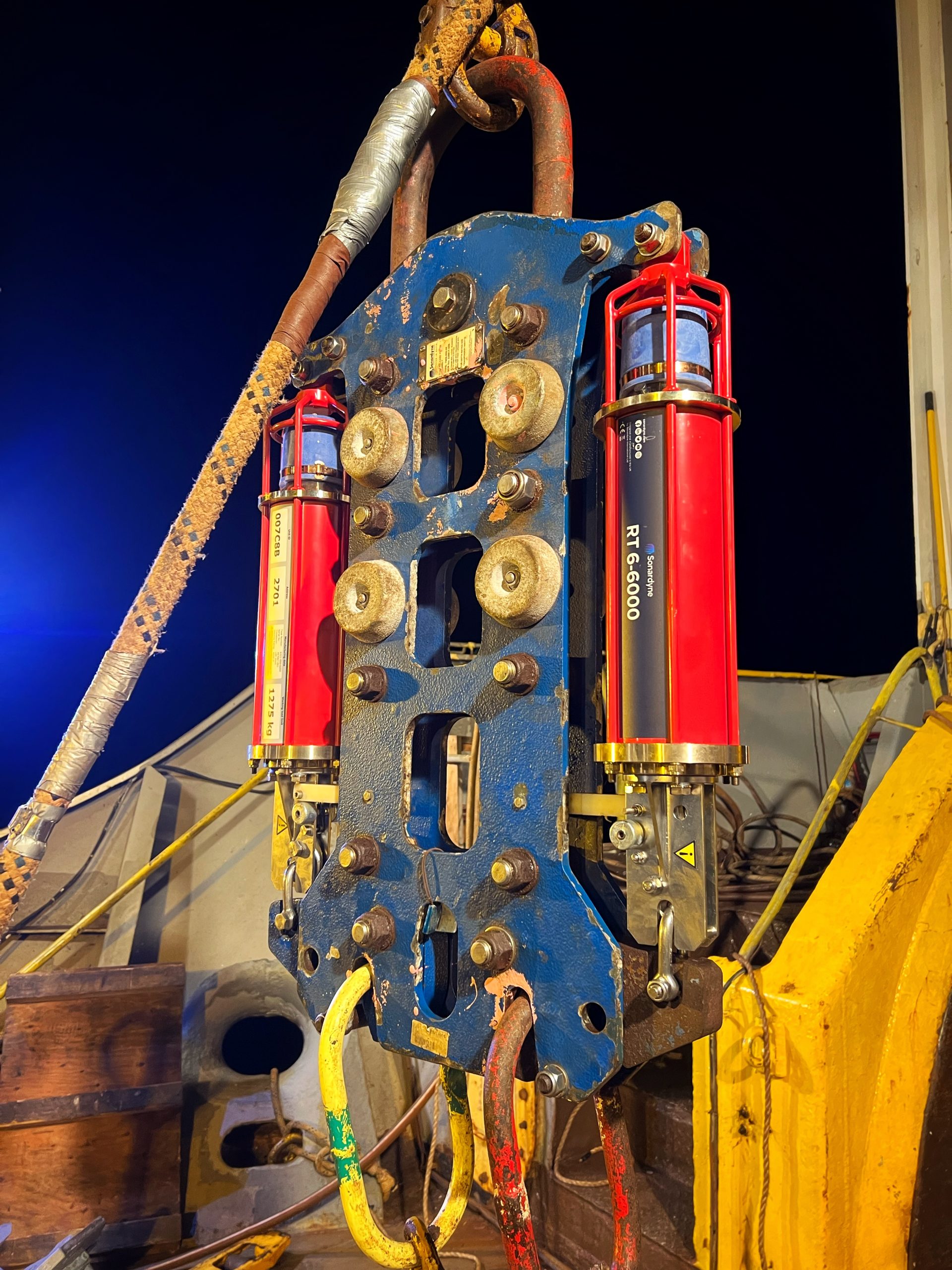
Acoustic releases are available for many different depth ratings. The RT 6-HD has the highest depth rating of 7,000m, designed to support applications from telecoms cable repair to structure installation with a working load limit (WLL) of 2,500kg. The mid depth rating option of acoustic release is the RT 6-3000 which has a depth rating of up to 3,000m designed for a wide range of sustained observation tasks which span years of in-situ measurements with a WLL of 1275kg. For deeper work, the RT 6-6000 has a depth rating of up to 6,000m and an LMF transducer. The RT 6-1000 has the shallowest depth rating of 1,000m which is a perfect, low-cost acoustic release for mooring environmental sensors with a WLL of 150kg.
-
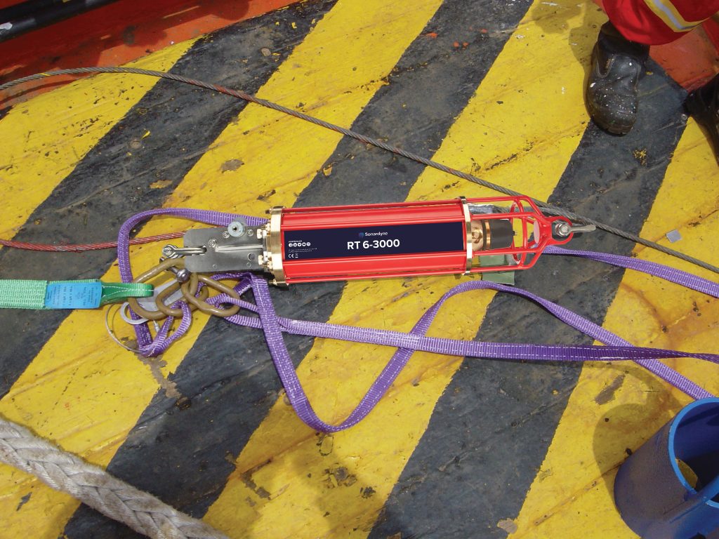
- An acoustic release ready for deployment
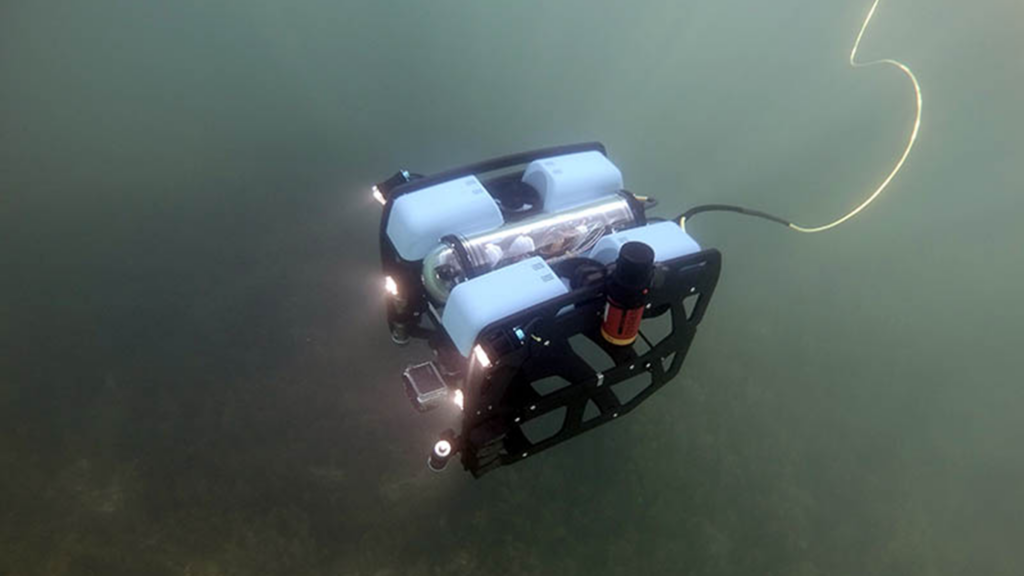
-

- An acoustic release about to be deployed
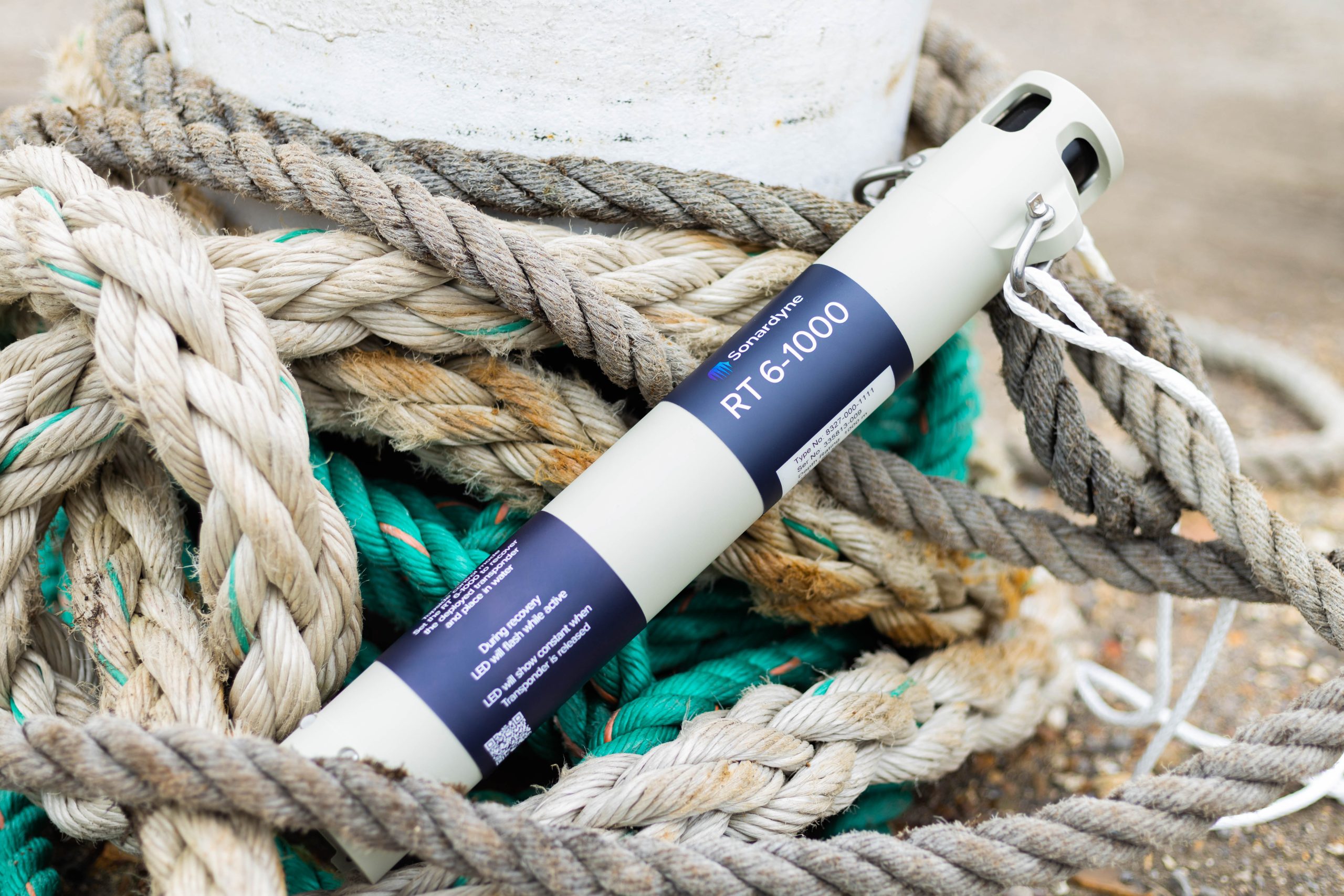
-

- Shallow depth rated acoustic release
More specific information about our family of Acoustic Releases can be found here.
Contact [email protected] for more information.
What is a USBL?
An Ultra-Short Baseline (USBL), is a method of underwater acoustic positioning which is used to calculate the position of underwater targets.
How does a USBL work?
A USBL system consists of a transceiver, which is usually mounted on a pole under a ship- and a transponder or responder which is normally on the seafloor or on an ROV, AUV or UUV.
A USBL system works by the transceiver transmitting an acoustic pulse which is detected by a subsea transponder, this then replies with its own acoustic pulse. The return pulse is then detected by the shipboard transceiver.
The time from the transmission of the initial acoustic pulse until the reply is detected by the transceiver is measured by the USBL system and then converted into a range. For subsea position to be calculated, both the range and angle from the transceiver to the subsea beacon must be calculated. Angles are measured by the transceiver which contains an array of transducers. A transceiver head typically contains 3 or more transducers separated by a baseline of 10cm or less.
USBLs are available for a variety of uses and operating ranges. Ranger 2 is our most capable tracking and DP (dynamic positioning) reference USBL, it is installed on a global fleet of vessels in all water depths with an operating range of up to 11,000m. Our Micro-Ranger 2 USBL is portable and quick to set up and is perfect for simple USBL tasks such as tracking an ROV, micro AUV or divers with an operating range of up to 995m. Our Mini-Ranger 2 USBL is suitable for those who need to track targets further, simultaneously and with survey-quality precision with an operating range of up to 4,000m.
-
- USBL tracking small ROV

-

- USBL being used on a USV to track underwater AUVs
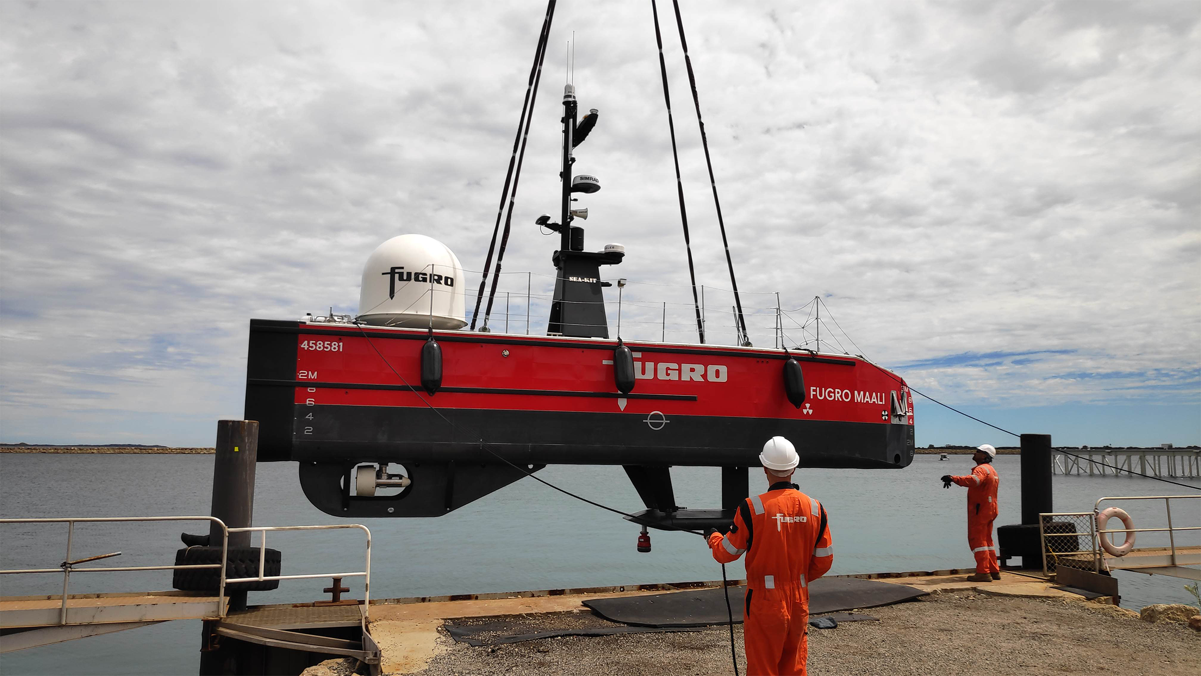
-
- USBL tracking a large AUV
More specific information about our USBLs can be found here.
Contact [email protected] for more information.
Configuring the iWand to connect serially in RT 6 Dunker Mode.
Dunker mode is when a iWand is connected directly to a transceiver via a cable which enables an alternative method to release a subsea instrument. Note: this is a depreciated mode that is unsupported; the Deck Topside should be used instead of this configuration
When using the iWand in RT 6 Dunker mode, the iWand will no longer communicate through the serial port as it is now configured for talking directly to a transceiver. In this mode the iWand cannot perform a hardware test or refresh.
To connect the iWand serially, RT 6 Dunker Mode must be disabled as follows:
1. On the iWand, select RT 6 Dunker Mode.

2. Select Off to return to standard mode.

3. The iWand should now connect to the transponder using the serial port.
For more information, please get in touch.
What is an ADCP?
An Acoustic Doppler Current Profiler, ADCP, is an instrument that uses sound waves to measure currents through the water column.
How does an ADCP work?
To measure water currents with sound, ADCPs use a principle of sound waves known as the Doppler effect. The Doppler effect is the shift in the frequency of a sound wave caused by movement between an emitting or reflected sound source and the receiver, whereby a sound wave that is moving toward you has a higher frequency and vice versa.
An ADCP works by transmitting “pings” of sound at a constant frequency out into the water column from its transducers. As these pings travel, they scatter off particles in the moving water and reflect back to the device.
If the particles are moving the scattered signal is Doppler-shifted, which means there will be a difference in frequency between the sound waves the profiler transmits and those it receives back. And it is this shift that is used to calculate water speed at the location of the particles.
The return time of scattered sound waves corresponds to distance from the instrument, with later-time returns relating to more distant water and vice-versa. So by measuring this together with the Doppler shift, an ADCP can measure current speeds throughout a water column i.e a profile of current measurements.
To get a three-dimensional water current profile, returns are combined from a minimum of 3 transducers. Many ADCPs have more than 3 beams, for purposes including provision of redundancy and error correction, and determination of wave and turbulence metrics.
ADCPs are available in many different frequencies, with choice of frequency being a compromise between profiling range and resolution. Low frequency instruments, like the Origin 65, will provide lower resolution data but to a greater depth range (around 800 m in the case of Origin 65). Whereas higher frequency instruments, like the Origin 600, have a smaller profiling range (around 50 m for Origin 600) but provide higher resolution data.
Contact [email protected] for more information.
Origin 65 has an integrated acoustic modem as standard, which facilitates remote communications when using an accompanying topside modem (sold separately) and the Origin Topside PC software.
The Origin 65 ADCP has an LMF (14-19 kHz) acoustic modem, so users with an LMF topside modem, such as an LMF Dunker 6 or HPT 7000L USBL transceiver, can communicate with a deployed Origin 65 as if it were cabled to a PC or laptop.
Just install the Origin Topside software, connect your topside modem to your laptop, and wake up the ADCP to be able to communicate with your Origin 65.
The integrated modem is 6G compatible, so can work with Sonardyne 6G topside modems, including dunkers and USBL systems.
For more information check out the Sonardyne 6G topside modems, and find out about the benefits of remote communications using Origin 65’s integrated acoustic modem.
Contact [email protected] for more information.
Origin 600 has an internal rechargeable battery as standard, providing many benefits over disposable internal batteries.
What are the risks associated with disposable internal ADCP batteries?
Seabed ADCPs are often powered by internal alkaline or lithium batteries. These allow the ADCPs to capture data for a period, but then need replacing once the device is retrieved from the water. Battery replacement involves opening the device, disconnecting and removing the old battery, and connecting and installing the new one. This invariably involves undesirable risk to the electronics, and occasionally it may be challenging to source a new battery due to component availability or shipping constraints.
What are the benefits of the Origin 600 rechargeable internal battery?
To mitigate problems associated with the replacement process of disposable internal batteries, Origin 600 has an internal rechargeable battery. This rechargeable battery also delivers a substantial cost saving over the life of the ADCP given that it can be used time and time again, with no need to buy a new battery for each campaign. What’s more, when Origin 600 is operated in conjunction with a topside modem, battery life can be monitored after the device is deployed, providing the extra benefit of confidence in knowing the instrument will not run out of power mid-deployment. For extra peace of mind, a battery reserve is built in, so even if the battery can no longer power ADCP measurements, the integrated acoustic modem can be interrogated for several months, allowing the device to be located long after it has stopped capturing current data.
What are the options for the Origin 600 rechargeable internal battery?
In addition to a single battery option, Origin 600 has a dual rechargeable battery option for those long-term monitoring or more power-intensive applications. Furthermore with Origin 600, you are not limited to the internal battery as you can also connect to an external disposable battery pack via the external wet connector. So whether you’re making a quick measurement, or a long-term campaign, Origin has you covered.
Contact [email protected] for more information.