Sonardyne
Support Centre

Origin 65 holds the key to help unlock Gulf of Mexico loop current eddy mysteries

The Gulf of Mexico is home to the highly energetic ocean circulation feature known as the Gulf Loop Current System (LCS). This current system influences all ocean processes in the gulf, characterised by highly disruptive Loop Current Eddy (LCE) events. LCEs are rings of warm water which rotate at speeds of up to four knots in a clockwise direction, measuring approximately 100-200 km in diameter, reaching down to depths of 500–1,000 m, and breaking away from the extended Loop Current around every 8-9 months. Loop Current Eddy events have serious implications for a great range of natural and human activities, from ecosystem dynamics and hurricane intensification to fishing operations and oil and gas exploration.

The challenge

The behaviour of the LCS remains difficult to forecast with sufficient accuracy to guide operations beyond a few days, yet its significance for processes and operations in the Gulf of Mexico drives a need to improve and extend forecasts of the LCS and LCEs. The difficulty has arisen partly because interactions of the upper currents with deep eddies have not been detectable in real time to guide numerical models.


Unlocking the Gulf current – a continuance

Sonardyne were introduced to this challenge back in 2018 when the University of Rhode Island launched a multi-year scientific study that included deployment of five Sonardyne Current Pressure Inverted Echo Sounders (CPIES) at depths down to 3,500 m in the area of the extended LCS.


The Sonardyne solution

Sonardyne’s modem-enabled CPIES were a key element in the initial two-year project. These instruments were part of a mass deployment to measure two-way travel time (or tau) over an extended area in order to map the local horizontal velocity and density fields in the extended LCS, as can be read at https://www.sonardyne.com/case-study/unlocking-the-gulf-loop-current/.

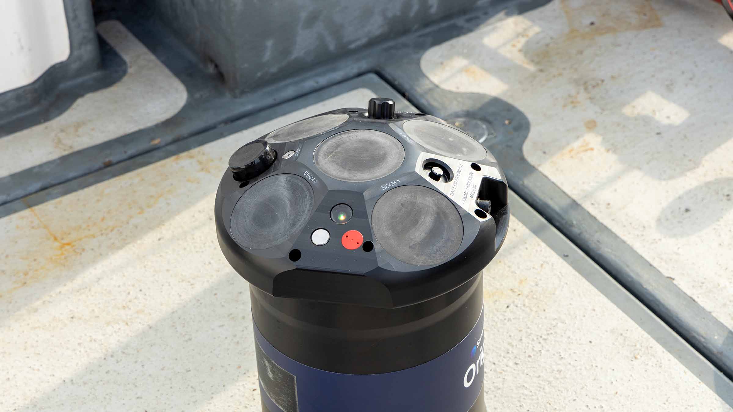
Soon after the 2018 deployment, Sonardyne began the development of Origin 65, a combined PIES and ADCP with acoustic modem to enable adaptive data harvesting. The benefit of Origin 65 over CPIES is that it not only supports but augments density/current mapping projects.

Where CPIES use a separate single point current meter to provide a deep reference velocity for calculated geostrophic currents, Origin 65 measures a whole profile of currents over a greater range. Being an all-in-one instrument, Origin 65 also removes the risk and expense of combining separate devices for a single application.

What’s more, by utilising Origin 65’s onboard Edge data processing capability, PIES data is time-synchronised and fused with the ADCP measurements for simpler analysis. After extensive trials, Origin 65 was launched in 2023.


“Pulses of strong currents pose a hazard to industry along steep escarpments in the deep Gulf. Moreover, their unexpected arrival compounds the hazard: satellite and near-surface observations and numerical models do not predict them reliably. We needed a forecast tool grounded in observations with adaptive reporting capability. We had a tall order for the observations: We needed to profile currents from the bottom through hundreds of meters above the bottom and we required fast acoustic telemetry capability. Sonardyne committed the engineering capability to develop a combined PIES and upward-looking low frequency ADCP with a vertical range of 800 m. It was an outstanding match to our needs, and Sonardyne’s fast acoustic telemetry capability was key to being able to harvest the data and report it ashore in near-real time.”

Professor D. Randolph (Randy) Watts, Professor of Oceanography, University of Rhode Island

The 2024 deployment

In 2024, funded by the US National Academies of Science, Engineering, and Medicine Gulf Research Programme and led by a team of scientists from the University of Rhode Island, five Sonardyne Origin 65 units were deployed alongside the original Sonardyne CPIES in the Gulf of Mexico (depth range of 1,800 – 3,200 m) for an initial 18-month measurement campaign.

Both the Origin 65s and CPIES have integrated acoustic modems enabling high-speed (up to 9,000 bps) acoustic telemetry to support wireless retrieval of data by an uncrewed surface vessel (USV) in addition to remote control of the instruments.

Despite similar telemetry capability, the volume of data generated by Origin 65 compared to CPIES is much greater, and therefore limited acoustic bandwidth presents a challenge when looking to transfer this substantial data via acoustic telemetry.

This is where Origin 65’s Edge onboard data processing capability comes into play to condense the bulky raw data into small packets of actionable information, easily exportable via the acoustic modem.

The five Origin 65 units were deployed with an Edge application (app) installed to perform combined onboard processing of the ADCP and PIES data. More specifically, the Edge app implemented a custom algorithm that produced an hourly compact (24 bytes) binary output containing a timestamp, the mean current speed and bearing in six depth-bins above the bottom, plus the mean of the PIES results.

The beauty of the onboard data processing was apparent during planned USV visits, where it took less than 20 minutes to acoustically harvest more than two months’ worth of data

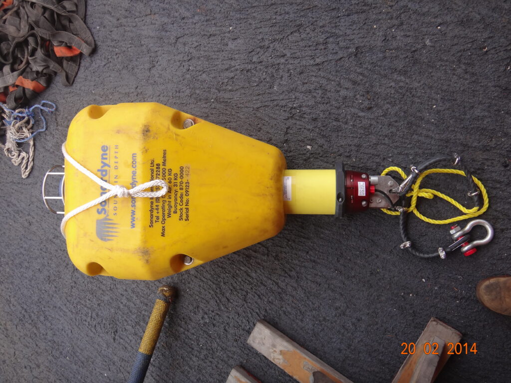
An assessment was conducted whereby the integrated acoustic release on one of the Origin 65 instruments was triggered after 66 days of deployment to allow recovery (Figure 1) of the device and complete data download for a thorough evaluation. This instrument was located in a water depth of 2,142 m.

Figure 1: Retrieval of the Origin 65 aboard the R/V Pelican.

Pies

The PIES portion of the Origin 65 performed consistently (Figure 2). Periods of increased scatter in the sound speed measurements are observable, but these are a result of higher ambient noise levels (pretrigger RMS), which correspond to higher sea states (local wave activity is a dominant source of acoustic noise given that in higher sea states the surface return from the PIES chirp is more spread out).

Figure 2: PIES sound speed and ambient noise (pretrigger RMS) measurements for the  deployment. The bottom plot compares ambient noise (pretrigger RMS) to the level of local wave activity using wind speed (as recorded by station Green Canyon 338, 124 km to the WNW of the deployment site) as a proxy for sea state.

ADCP

Velocity data demonstrates expected current behaviour (Figure 3), with velocities much larger in the Eastward and Northward directions than in the upward direction. The lack of significant apparent velocity in the vertical direction indicates that there is no systematic bias in the beam-frame Doppler velocities.

In addition, the observed velocity signals (large blue and red patches) vary on timescales between days and weeks, which is expected.

Of particular interest, it can be seen around 6th June, the prevailing current changed from South-Easterly to North-Westerly over the course of around two days.

This corresponded with a sudden increase in scatter density, thought to be an indication that the seabed was disturbed by the changing current.

Figure 3: Components of the Earth-frame velocities for the 66-day deployment (60-ping ensembles).

Low scatterer concentration in the deep waters (>2000 m) of the Gulf of Mexico reduced the effective profiling range of the Origin 65 from its achieved maximum range of > 800 m. However, with a sufficiently long averaging period it can been seen that the current velocity signal is present for the entire 800 m range of the Origin 65 (Figure 4).

Figure 4: Comparison of 24-hour averages of Eastward current velocity for different altitude bins. Performing increased averaging shows that a consistent current velocity signal is exhibited across the 800 m range of Origin 65.

“Our collaboration with the University of Rhode Island has been instrumental in augmenting our PIES technology in the form of Origin 65, a combined ADCP and PIES, for oceanographic study of geostrophic currents fields like that found in the Gulf of Mexico. We’re delighted to see Origin 65 being applied in this vital study, and by extension, to be able to support research efforts to improve and extend forecasting of the LCS and LCE behaviour with the accuracy desired. We look forward to continuing our relationship with the University of Rhode Island, and to seeing further successful USV data harvests from the Origin 65 units over their deployment period in the Gulf of Mexico.”

Michelle Barnett, Business Development Manager – Ocean Science, Sonardyne


What’s more, evidence of diel plankton migration is apparent with the repeated appearance and disappearance of a scattering layer between 500 m and 800 m height above the bottom. This pattern has a period of roughly 24 hours with the scattering layer clearly visible in daylight hours, as is consistent with the cycle of diel vertical migration observed ubiquitously in aquatic systems throughout the world.

This is nicely demonstrated in cross-correlation data, where values increased to around 80% on a daily cycle in response to the plankton migration (Figure 5). This cross-correlation data helps to indicate the effective maximum range of the system of around 800 m.

Figure 5: An excerpt (4 – 7th June) of unaveraged cross-correlation data for each of the four beams of the Origin 65 demonstrating a clearly observable diel vertical migration pattern. The lower plot represents the local time, with the colour being a function of the local solar altitude.

“This suite of instrumentation and platforms will help refine predictive tools for future applications in the Gulf. Looking ahead, the combination of Sonardyne Origin 65 current profilers and adaptive data-harvesting technology opens the door for long-term deployments in deep water – anywhere in the world. This is very exciting: we could access remote and critically important regions supporting sustained observations and advancing science.”

Professor Kathleen (Kathy) Donohue, Professor of Oceanography, University of Rhode Island


What’s next?

Two successful data harvests by a SeaTrac SP-48 USV equipped with a Sonardyne HPT 7000 L transceiver head have already been conducted. A third data harvest is scheduled for the end of July and the instruments will be recovered in September 2025. Keep an eye on our website and social media for further information about this and the data captured.

If you have an operational challenge for Origin 65, or any other Sonardyne product, please contact us.

Jump to

Overview

Elevate your ocean operations with Origin – High resolution ADCP solutions

How would wave, turbulence or mean current data at up to 10x the industry standard resolution enhance your ocean operations? What about reduced operational costs, risk and time?
Introducing the Origin family of Acoustic Doppler Current Profilers (ADCPs)….

Origin rewrites the story of your relationship with an ADCP

Our Origin family of ADCPs represent the latest in cutting edge underwater profiling technology. Able to analyse mean currents, waves and turbulence, and integrate with external sensors to provide pH levels, temperature and other data, Origin delivers comprehensive, reliable and timely data sets for your underwater operations.

With on-board Edge data processing and built-in acoustic modems, Origin can also process and deliver your data in almost real-time. This data is delivered in conventional PD0 format as standard but can be programmed to present results in our exclusive A-gram and B-gram formats, giving you up to 10 x greater spatial resolution detail.

Available in two models, Origin 65 for deep water profiling and Origin 600 for near and inshore waters, there is an Origin ADCP to suit your operation.


Why should you invest?

Origin ADCP family gives you the data you need, at a level of detail not available anywhere else on the market. Their ability to integrate with third party sensors unlocks additional capability and protects your investment.

Rechargeable batteries in Origin 600 give you rapid redeployment times as the unit can be recharged on the back deck whilst data is being downloaded before it’s returned to the seabed. Depending on your programme requirements, Origin 65 can operate for up to two years on the seabed before needing to replace its batteries.

Whichever size suits you best, they are both compatible with our Ranger 2 USBL equipment so you can harvest data and update your operation schedules mid-mission.

Origin 65

Origin 65 revolutionises what you can do with a deep water ADCP. It combines state-of-the-art acoustics, sensors, and data into one payload providing you with an unprecedented view of the deep. It’s a versatile, reliable and high performance ADCP with on-board Edge processing for data optimisation and an integrated modem for remote control and data access.

For the full picture of what your Origin 65 is capable of, please visit its dedicated product page.

Origin 600

With a 60-m current profiling range, on-board Edge data processing and an integrated acoustic modem, Origin 600 provides you with in-situ, high resolution measurements with on-demand data retrieval – reducing survey costs, risk and time. Choose between industry standard data formats or our exclusive proprietary format offering up to ten times greater spatial resolution.

For the full picture of what your Origin 600 is capable of, please visit its dedicated product page.

Remote control

The integrated acoustic modem enables actions with the ADCP already in the water, delivering in-field flexibility and data assurance.

Reduced risk

Remote, safe and low-cost data: Edge customised and optimised data can be harvested acoustically with a small and efficient USV to reduce overall ship time, human intervention and associated risk.

Expanded functionality

ADCP data can be supplemented by and Edge-fused with data from external sensors so you can really get the most out of a single device deployment and the data generated.

Operational flexibility

It can support short-term and long-term current monitoring projects, using our Ranger 2 systems to harvest data for actionable insights during monitoring periods.

Straight out of the box navigational enhancement for offshore out of straightness surveys

Fugro are already delivering safer, faster and more sustainable offshore operations – as you may have read in our previous case study about the Mini-Ranger 2 USBL system being used to support ROV operations from a USV. Working with us, Fugro are continuing their pioneering remote operations with their fleet of uncrewed surface vessels (USVs) deploying remotely operated vehicles (ROVs) – changing the game for offshore infrastructure surveys. Read on to see how our SPRINT-Nav Mini is being used to enhance multibeam echosounder (MBES) on Fugro’s remote operations, providing incredible results.

The challenge

Out of straightness (OOS) surveys are used for acquiring information about the vertical and horizontal configuration of offshore pipelines. They provide operators with information on the presence or otherwise of buckles and bending in a pipeline, which may be engineered or not, and require monitoring during the operational life of the pipeline or flowline asset.

Fugro have been conducting OOS surveys on pipelines for major energy companies in Australia for many years. These surveys were conducted using a Norbit WBMS Narrow Multibeam echo sounder mounted on a Fugro inspection class ROV deployed from Fugro’s 12m Blue Essence® USVs, Maali and Kwilena.

ROV missions along pipelines can be erratic and unreliable due to the distance between the transceiver (USV) and transponder (ROV) when using just USBL positioning. For Fugro’s OOS survey customers, highly accurate data is essential. This has led to their requirement for the highest accuracy navigation and imaging available to the small ROV.

Fugro set us the challenge to provide a navigation solution that would enable the customer requirements of high-quality data using a small ROV. We worked with Fugro to trial SPRINT-Nav Mini and demonstrate the capabilities of the system.

The solution

SPRINT-Nav Mini is the world’s smallest hybrid navigator, combining INS, DVL, AHRS and a pressure sensor in one factory calibrated unit. SPRINT-Nav Mini’s true north seeking gyrocompass means that it delivers reliable surface and subsea navigation. Adding this navigation capability to any marine robotic system allows users more control and turns their vehicles into far more accurate inspection and survey platforms.

With everything you need for navigation packed into a single low Size, Weight and Power (SWaP) package, SPRINT-Nav Mini is simple to integrate into any marine vehicle along with other payload sensors, like Fugro’s MBES. Its impressive precision of 0.05% of distance travelled accuracy on a typical survey alongside our revised heading, pitch and roll specification means that advanced mapping is now possible on smaller platforms deployed from USVs.

“SPRINT-Nav Mini is becoming increasingly vital for geophysical survey operations where SWaP is critical. Users need accurate and high output rate navigation streams for real-time compensation of imaging sensors.” Says John Houlder, INS Product Manager, Sonardyne, “SPRINT-Nav Mini provides robust real-time results that are improved even further once post-processed in our Janus software.”

After demonstrating SPRINT-Nav Mini’s capabilities, Fugro purchased the system and have been deploying it on their inspection ROV, which in turn is deployed from the Blue Essence® USV. With the Fugro team’s input we have been able to revise our specification for SPRINT-Nav Mini, improving its suitability for use with MBES on geophysical survey. These revisions include:

Pitch and Roll: 0.1 to 0.02° RMS

Heading: 0.15 to 0.1° RMS

Find out more about SPRINT-Nav Mini here

The results

Fugro utilise SPRINT-Nav Mini data within the ROV command and control software, Starfix® navigation, including their Camblock Vision based augmented reality system, and for processing MBES data. In the case of MBES processing, they are also conducting pipeline OOS surveys to a maximum depth of 200 metres.

The images below show some example data Fugro has gathered with MBES positioned using SPRINT-Nav Mini and post processed with our Janus software. Janus is our quality control and INS post processing software. It allows quick and easy data editing, post-processing and data export. Find out more about Janus here

If your offshore operations are also reliant on fast, efficient and accurate data to keep your business competitive in an ever-changing marketplace, take a look at our full range of navigational products here.

“We were attracted to the SPRINT Nav Mini form factor and integrated (factory calibrated) DVL. The ability of the DVL to achieve bottom track from the surface for most of our deployments in water depths less than 200 metres also brings efficiencies to our operations. The performance we’ve seen from SPRINT Nav Mini after Janus processing for MBES surveys is on a par with larger work class ROV deployed systems Fugro uses.”

Matt Lussu Principal Hydrographic Surveyor, Fugro

“Deploying robotic platforms over-the-horizon to deliver important information to clients in the way that Fugro are doing means that they have to trust not just their platforms, but the payloads onboard. Having SPRINT-Nav Mini providing navigation enables this trust as well as the excellent MBES data that we see here. Fugro have chosen both our Mini Ranger 2 for positioning and are now benefiting from SPRINT-Nav Mini for navigation, underlining our value to pioneering marine robotic operations. “

Aidan Thorn Business Development Manager – Marine Robotics, Sonardyne

Rapid leak detection for subsea production and storage sites

The ocean is a critical habitat that needs protecting. With decades of experience in sonar detection systems, our technologies provide an essential early subsea leak detection and warning system, across your oil and gas assets, CO₂ storage and offshore hydrogen transport and storage sites.

The challenge

A supermajor international energy company, with production infrastructure in more than 2,000 m (6,500 ft) of water depth, wanted a single subsea leak detection system that could be permanently installed to detect and localise, within seconds, oil or gas leaks across a wide area of its subsea infrastructure.

Existing sonar-based solutions are mostly based on sensors attached to subsea assets to detect leaks at specific or very localised locations, i.e. within a few metres. Alternative, non-acoustic, systems rely on anomalies in production data rates, which can be challenging should the leak occur upstream of the monitoring device.

At worst, leak detection relies on viewing the leak at the sea surface in the form of an oil-based sheen – when it’s already too late. This option is also limited when it comes to detecting leaks at gas producing fields and offshore carbon capture and storage (CCS) sites.

With a globally significant installed and aging asset base, as well as new infrastructure in the form of offshore CO₂ and hydrogen transport and storage, there’s increasing interest in alternative leak detection technologies that can operate autonomously and sustainably over wide areas in all water depths.

The solution

Developed by Wavefront Systems and manufactured and commercialised by Sonardyne, our Sentry Integrity Monitoring Sonar (IMS) is the only commercially available wide-area subsea leak detection system. A single Sentry head can provide 360-degree coverage of a 1,200 m diameter area, or more than one billion cubic feet of seawater, automatically alerting the operator as soon as an oil or gas leak is detected.

Detection rates are very impressive, with Sentry being able to detect monophase gas down to 0.1 litre per minute (equivalent to around 1 barrel of oil per day) or monophase oil to 1 litre per minute (equivalent to 9 barrels of oil per day). That means operators can react quickly to an infrastructure integrity breach before it becomes a bigger environmental and financial problem.

Sentry is an active acoustic-based solution that is based on a remotely operated vehicle (ROV) deployable low-power sonar proven for long-term monitoring. It’s available as a wired solution, that can be connected via existing subsea infrastructure directly into a surface asset. There, a Sentry workstation with graphical user interface (GUI) is able to provide users with clear real-time and automatic alerts of any oil or gas leaks.

It’s also available as a wireless, battery-powered solution for semi-permanent deployment, with data transmitted acoustically to a topside transceiver system. The transceiver can be deployed from a platform, buoy, vessel of opportunity or, now more commonly, via uncrewed surface vehicles (USVs).

The results

To make sure Sentry was fit for the oil major’s needs, the operator oversaw a trial deployment of a hardwired Sentry IMS. This included using a simulated monophase oil target, in this case nitrile-rubber strands, equivalent to a nominal oil leak rate of around 150 barrels per day.

The trials provided fast and accurate results. Detection and classification of the equivalent release of 100 barrels of oil per day out to 245 m (820 ft) was achieved, a distance constrained only by limitations of the trial set up. Leak detection was alerted within seconds of the simulated leak skid being deployed.

Sentry’s capability, however, covers 100 barrels per day mono-phase oil leaks at distances of up to 740 m (2,427 ft). It is even more sensitive to mono-phase gas leaks, with the system being capable of detecting down to the equivalent of just 1 barrel per day at 500 m (1,640 feet) or 100 barrels per day (as measured at depth) at 1,000 m (3,280 ft).

Following the extensive and successful trials, the operator purchased the Sentry IMS system for installation at its deep-water field development.

0

degree

coverage

0

m

diameter area

0.1 litre

per minute gas detection

Supporting the energy transition

As we transition from fossil fuels to new energies, many are looking to offshore as potential sites for CCS, as well as for hydrogen production.

Sentry helps to de-risk these projects. It ensures that, should carbon sequestration and offshore hydrogen transport and storage sites develop a leak, their operators will be alerted quickly, enabling a swift response, preventing larger environmental and financial problems.

Read about how we proved subsea leak detection capability for carbon capture and storage sites (CCS) through an Energy Technologies Institute research project, with partners Fugro, National Oceanography Centre, British Geological Survey and Plymouth Marine Laboratory here.

Observer, the new standard for monitoring

Observer, our intelligent asset monitoring system, is now the clear choice for your next project, delivering a significant performance boost over AMT and SMART. Click here to find out more.

Keeping production flowing by understanding subsea asset movement – wirelessly

An important feature of extending, or even preserving, offshore life of field is to know and understand what is happening with deployed subsea assets. Are they vibrating, perhaps they are slowly walking from their original position, is this happening as a one-off or regularly due to flowline properties? Oceaneering learnt all of this by deploying smart and intelligent sensors at a deep-water development offshore Africa.

The challenge

The worldwide quantity of flowlines, spool pieces, pipeline end termination units, risers and all manner of other installed subsea assets is staggering. All serve as important interconnecting elements in the overall offshore hydrocarbon supply chain. With an aging asset portfolio, it is sometimes very difficult to understand how these assets have been moving during their operational life and what this means to their accumulated fatigue figures and, therefore, safe end-of-life point.

At one offshore field development, Oceaneering, was set a challenge by an international operator. They suspected spool piece movement caused by slugging events, and asked Oceaneering Inc. to provide subsea data for third party analysis so the extent and frequency of movement could be determined. They hoped this would help with the introduction of mitigation measures that would ensure safe and controlled production from the connected producing wells.

With the field located in over 1,000 m of water and with no designed-in points for sensor mounting or hardwired connectivity, this was easier said than done.

The solution

Oceaneering turned to our wirelessly communicating and intelligent monitoring sensors called Subsea Monitoring, Analysis and Report Technology, or SMART for short. Additionally, a series of Autonomous Monitoring Transponders, or AMTs, were deployed within a seabed array to detect any longer period movement that SMARTs would be unable to detect.

Battery operated SMARTs were chosen as they incorporate a low-power inertial measurement unit, or IMU, that can precisely measure the installed sensor’s six degrees of freedom. This means that 3-axes of rotation and 3-axes of acceleration relating to the SMART sensor’s movement can be measured at very high sampling rates over a measurement window set by the operator.

This measurement window, which can be adjusted acoustically at any time from a topside transceiver, can be set between a minimum period of approximately 5 minutes to continuous recording. However, a one-hour measurement window is far more commonplace.

Once the measurement window has ended, SMARTs analyse the recorded raw data, producing and storing one statistical summary file for each window period. When required, these summary files can be requested for wireless transmission through the water column from each SMART’s location to a topside transceiver using Sonardyne’s fast and robust 6G Wideband 2 acoustic protocol on the Dunker 6 LBL and telemetry transceiver.

Importantly for the operator, all SMART raw, time-series, data is securely recorded and saved in-situ for more detailed analysis post-recovery.

Through the combination of edge analytics, low power electronics and acoustic communications, SMARTs could be installed for over a year. Even longer deployments are achievable by supplying larger battery packs or reducing the sampling frequency.

SMARTs are designed for high frequency motion monitoring, but the operator was equally concerned that longer periods of motion were in play that may have caused the subsea asset to gradually move from its installed position. Thus, monitoring for possible flow induced vibration (FIV) and vortex induced vibration (VIV) was also required. To monitor this motion, Oceaneering Inc. chose another Sonardyne sensor called an AMT.

AMTs are used for long-term survey and monitoring applications where instruments are needed to acquire acoustic ranges and other sensor data, like pressure, temperature, and sound velocities, without any surface control. By creating a Long Base Line (LBL) array of static seabed located AMTs with an AMT on the asset needing to be monitored, highly accurate measurements of any horizontal movement of the monitored asset can be measured, accurately timestamped, and logged. Vertical movement of the asset-mounted AMT can also be determined by the recording of precise pressure sensor information and comparing it to those from the control array.

An additional benefit identified by Oceaneering is that data from the AMTs can be wirelessly recovered using the same topside hardware as that of the SMART, resulting in less topside subsystems.

The results

Oceaneering mobilised the equipment in 2018 and it has been in operation ever since. The performance of the SMARTs in determining motion characteristics, coupled with the motion mitigation measures that were introduced, enabled the operator to continue producing safely and within the design life of the installed spool pieces. What’s more, the operator now has a far better understanding of their accumulated fatigue figures for the spool pieces and is able to determine the safe end-of-life point for their subsea assets.

Underpinning the Indian Tsunami early warning system

Sonardyne Bottom Pressure Recorders (BPR) have been at the heart of the Indian Tsunami Early Warning System (ITEWS) since its establishment in 2007. Based on Sonardyne’s workhorse Compatt transponder, our BPR instrument was developed in direct response to the devastating 2004 Indian Ocean Tsunami.

The challenge

30% of India’s population (ca. 420 million) live on its 7,500 km long coast and are consequently highly vulnerable to devastating Tsunamis such as the one that occurred on 26th December 2004. This killed over 230,000 people in the Indian Ocean region, with 10,749 confirmed deaths in India and another 5,640 missing. While seismometers are an important component of Tsunami warning, only Bottom Pressure Recorders can detect the passage of an actual Tsunami. Indeed, Tsunami warnings based purely on seismic data have the potential to produce false alarms, which are costly in wasted evacuations and undermine public confidence.

The essential elements of a Tsunami Detection System (TDS) are:

1. The capability to detect a Tsunami – While a Tsunami may arrive at the coast many metres high, in open ocean they pass almost imperceptibly and may only be a few centimetres in height, although this elevation in sea-level can be maintained for as long as 20 minutes.

2. The functionality to provide this detection ashore with sufficient warning time – A Tsunami travels (in ms-1) at roughly the square root of the depth of the water (in m) multiplied by the acceleration due to gravity (9.81ms-1): In short, it travels faster in deeper water, so for example, in 1,000m of water it will be travelling at over 1,100 kmh-1. In India’s case, the Andaman-Sumatra and Makran subduction zones are located within a few hours Tsunami travel time of the Indian coastline

3. High reliability in delivering the detection information ashore – BPRs, as the name implies are deployed on the seabed, so rely on robust telemetry, which has to operate even in poor weather conditions continuously 24/7/365.

The solution

The catastrophic 2004 Indian Ocean Tsunami led Sonardyne’s founder, John Partridge, to initiate development of a variant of the Compatt 5 seabed transponder to detect a Tsunami passing overhead.

With an extensive track record in the oil and gas industry, this instrument was ideal to form the heart of a TDS requiring very high reliability. Nevertheless, integration of a Digiquartz pressure sensor to enable the Compatt 5 as a BPR, required significant development. This particularly involved reduction of the power required for continuous operation on battery power. Similarly, a new transceiver with low quiescent power, capable of long endurance deployment on a surface telemetry buoy, also had to be developed.

Development was so rapid that when India’s National Institute of Ocean Technology (NIOT) in Chennai, started looking for a TDS in 2005, it was ready for competitive field trial. Sonardyne’s solution was subsequently selected in 2006, leading to deployment of operational systems in the Bay of Bengal and Arabian Sea in 2007.

In normal operation the Digiquartz pressure sensor in the BPR continuously measures water pressure and this data is stored every 15 seconds. The pressure data is then acoustically transmitted every hour to the surface, where an acoustically baffled transceiver, mounted beneath a buoy, receives this data. The buoy is linked to NIOT’s Mission Control Centre (MCC) by satellite communications, so that not only can data be transmitted ashore quickly, but also the health of the BPR is remotely monitored and, if necessary, reconfigured.

Embedded in the BPR is the National Oceanic and Atmospheric Administration’s (NOAA) Tsunami detection algorithm, which compares each measurement to the predicted pressure [Figure]. This predicted pressure uses the previous 3-hour history to take account of tide, weather and temperature variation. Should the difference between the two exceed a programmable default threshold of 3 cm for two consecutive samples, the BPR switches into Tsunami Alert Mode, which then initiates a sequence of data transmissions for the next few hours.

Sonardyne’s Wideband acoustics are central to the functioning of the system, and with the subsequent replacement of the Compatt 5 with Compatt 6, Sonardyne’s latest TDS offering is equipped with the most robust and efficient wideband acoustic telemetry available.

Of India's population

0

%

live on its long coast line

Monitoring

24/7/365

The results

Soon after the first batch of BPRs were deployed, on the 12th September 2007, the system detected its first Tsunami, which was triggered by an 8.2 magnitude event off the coast of Sumatra at 04° 30’ S 101° 18’ E. How the Tsunami generated was tracked across three of the Indian Tsunami Buoys (ITB) is shown in the gallery.

Located between 1,760 – 2,300 km away, all three stations recorded the seismic ground wave arrival between 7 – 12 mins after the event started. Between 2 – 3 hrs later, the wave itself, which was less than 10 cm in height, passed over the three BPRs, indicating that it had travelled at between 740 – 800 km/h over this period.

Today, Sonardyne’s TDS continues to deliver bottom pressure and event data to NIOT, which is responsible for delivering sea-level data to the Indian Tsunami Early Warning Center (ITEWC) at the Indian National Centre for Ocean Information Sciences (INCOIS) in Hyderabad. In 2014, NIOT reported that system data availability had been 98.83%, with a Mean Time Between Failure (MTBF) of 1.62 years, noting that the majority of these failures were due to external impacts, including weather and human interference with the surface buoys, resulting in damage to surface communication and data systems.

SMART to Observer

SMART has been obsoleted and has been superseded by Observer. Visit the product page for more information.

Monitoring slugging events and spool piece fatigue

Thousands of kilometres of pipeline, flowline, and interconnecting spool pieces are installed on the world’s sea and ocean floors. They create vast networks and their design can be complex, having to account for a huge array of variables, from water depth to expected flow composition and behaviour.

The challenge

Sometimes, it’s not always possible to account for all of the variables that an oilfield infrastructure is subject to. This can lead to issues. External vortex induced vibration (VIV) or internal flow induced vibration (FIV), which can sometimes be caused by slugging. Slugging is created by variable or irregular flow of gas and fluids through risers, pipelines, flowlines or spool pieces.

These issues can cause problems for process equipment, impact production efficiency and, critically, accelerate pipeline fatigue. This has knock-on effects for design life. It can even cause pipelines to be displaced, entrenched or erode the supports they stand on.

When FIV occurs, pipeline engineers need all the information they can get about just how much this is happening and to what degree. This enables them to re-calculate the remaining fatigue life of the infrastructure and decide on the best remediation methods. Unfortunately, monitoring exactly what is happening – what forces the pipelines, flowlines or spool pieces are being subjected to – can be challenging, especially in deep water.

International subsea engineering company Oceaneering International Inc. was asked by an operator to solve this exact problem. They had a number of spool pieces deployed in more than 1,000 metres of water, running between riser bases and flowline termination assemblies. They were being subjected to sudden and frequent slugging movements.

These movements had already resulted in new spool piece supports having to be installed. The operator’s engineers needed to assess the resilience of the new supports and learn more about the vibration the spool pieces were encountering. The challenge was that no motion monitoring sensors had been fitted prior to commissioning. The solution would need to provide accurate and accessible data using a technique that was not cost-prohibitive to install and operate.

The solution

Oceaneering’s solution used an innovative, wireless approach with Sonardyne’s Subsea Monitoring, Analysis, and Reporting Technology (SMART) sensor as a key element of the project.

SMART sensors are, well, smart. They contain low-power MEMs-based (micro-electric mechanical systems) inertial measurement units (IMUs), subsea processing power and integrated acoustic modem capabilities. This means they can autonomously measure, log and process high-frequency, pipeline or spool piece acceleration and angular rate motion over pre-programmed monitoring intervals.

Importantly, SMARTs, which can be integrated with many different subsea sensors to suit a wide variety of applications, process data at source. This is then sent as small statistical summary packets of data – based on parameters set by the user – through the water column to a surface transceiver. This method reduces the need to send time-series, or raw, data up to the surface for analysis, which prolongs battery life, maximizes bandwidth availability and provides useful information to engineers faster. It’s edge analytics and subsea communication technology in one battery-powered autonomous compact unit. And it’s able to work on extended deployments down to 7,000 metres water depth.

For the high-frequency motion, SMARTS were installed on each spool piece at a location between the riser and flowline termination assemblies. To monitor lower frequency movement on one of the spool pieces, another Sonardyne technology was used: Autonomous Monitoring Transponders(AMTs).

AMTs are most commonly used for long-term survey and monitoring tasks where instruments are needed for acquiring acoustic ranges and sensor data without surface control. They time-stamp data and log it internally, to be retrieved when it’s needed at the surface.

By creating a Long BaseLine (LBL) array of “static” AMTs, to which “mobile” AMTs installed on a spool piece and fitted with sound velocity sensors can range, highly precise measurements of any horizontal movement of that spool piece can be monitored and logged. By fitting the mobile AMTs with Digiquartz pressure transducers, vertical motion could also be tracked accurately within the array.

Before installing the SMARTs and AMTs, Oceaneering surveyed the seabed location. This was done to determine the LBL array design and SMART and mobile AMT positioning. Oceaneering designed and built ROV-installable spool monitoring clamps. This allowed the SMARTs and AMTs to be easily attached to the spool pieces. For the LBL array, four AMTs were placed in tripod stands at predefined locations for optimal ranging.

Following installation, confirmation that all the SMARTs and AMTs were working and a post-installation survey, the autonomous and intelligent instruments were then just left to do their work. A huge benefit of both instruments’ design is that they can be left unattended for three years thanks to their internally monitored lithium primary cells.

Anyone with these instruments deployed in their field has a choice in how to collect the data generated. If it’s close to a topside facility, they can deploy a Sonardyne Dunker 6 transceiver permanently, via a deployment pole for the duration of the monitoring, or temporarily over-the-side, via a winch or A-frame.

If the subsea infrastructure is more remote, they could periodically send a support vessel or an unmanned autonomous surface vessel with a Dunker 6 to harvest the data. For this project, while the site was deep, it was close enough to the customer’s production facility. Oceaneering chose temporary deployments, using the Dunker 6 from an onboard crane, as and when data collection was required.

The results

Since commissioning in the summer of 2018, continuous SMART monitoring of the spools, at four-minute intervals has taken place. Packets of data from both SMART and AMT devices, including raw runtime data, have routinely been sent to the surface. Once received, it has been analysed and used in predictive modelling. This has enabled the operator to calculate the accumulated fatigue and remaining operational design life of their assets.

Gaining access to the spools’ motion characteristics has been invaluable to the operator. It’s data they would have been expensive to access through other means. It has led to a deeper understanding of each spool’s motion frequency, rotation angles and cycle times. Where previously the operator had concerns about the remaining operational life of the spools, they now know the operational life is within the limits of the productive life of the field.

This is a great result for the operator, but also for Oceaneering and Sonardyne. By working together we were able to find a cost-effective and viable solution for the operator and future customers with similar challenges. By combining our expertise and flexible instruments as an integrated solution, the supply chain is able to tackle operators’ deepest challenges, quite literally.

AMT to Observer

Observer, our intelligent asset monitoring system, is now the clear choice for your next project, delivering a significant performance boost over AMT. Click here to find out more.

Rising to the challenge: riser tower monitoring

When Petrobras's Cascade and Chinook development went into production in 2010, it claimed two major milestones. It was the first floating production, storage and offloading (FPSO) facility used to accept production from the fields in the Gulf of Mexico, at 2,600 m. It was also the world's deepest operating FPSO.

The Cascade Chinook fields lie 180 miles offshore in the ultra-deep water of the Walker Ridge block. Petrobras America Inc. (PAI), the fields’ operator, fast tracked the development with the use of a converted tanker (later sold to Murphy Oil who now operate the FPSO).  

Oil production is facilitated through free standing hybrid risers (FSHRs) connected to flowlines from the field to serve the FPSO, delivering oil and gas to the surface for processing and exporting processed gas to a subsea pipeline.  

Crude is offloaded to a shuttle tanker. All risers and umbilicals are integrated into a disconnectable submerged turret buoy that allows the FPSO to weathervane and move off-station as required.  

Life-of-field monitoring

To maintain the integrity of the FSHRs, the Subsea Technology Group from Petrobras’s R&D Centre in Brazil, prepared a specification for PAI of a comprehensive life-of-field subsea monitoring system and contracted BMT Scientific Marine Services as the systems integrator responsible for its delivery.  

BMT has experience in the development of offshore monitoring systems and, following the successful development of a similar system for the Petrobras P·52 platform in Brazil in 2007, BMT again chose to partner with Sonardyne for the positioning and telemetry component of the riser monitoring system. 

The primary requirement for the acoustic instrumentation is to monitor the position of each riser tower and of the turret buoy relative to the seabed. In addition, integrated sensors monitor depth, temperature, inclination and sound speed whilst the integrated modem transfers data from the load and attitude monitoring system on each riser tower to the turret buoy. The system uses Sonardyne Wideband acoustic telemetry to guarantee high speed and reliable data communications for all these tasks. 

Integrity – Measure, command and monitor

To ensure line-of-sight to each riser tower without obstruction by the flexible risers or mooring lines, the turret buoy was equipped with three of our transceivers. The transceivers perform the following multiple functions: 

  • Measure ranges directly from themselves to the seabed transponder array in order to provide an accurate position for the turret buoy. 
  • Send commands to transponders mounted near the top of each riser tower, instructing them to measure the ranges to the seabed array. The positions of the risers can then be accurately determined.  
  • Acquire sensor data from the riser transponders and the seabed array. 
  • Send commands to, and recover data from, BMT’s data logger on the risers, fitted with an acoustic modem.

The transponder on the risers and on the seabed are versions of our Autonomous Monitoring Transponders (AMTs) which operate an efficient Wideband command protocol. 

This allows much faster set up of transponder parameters and enables the sensors fitted to the riser transponders to be measured and reported at the same time as the acoustic measurements are made, greatly speeding up the acoustic monitoring cycle. 

In normal operation, data acquisition will be controlled by the topside monitoring system on the FPSO. In the event of a disconnection due to adverse weather or maintenance, the subsea system continues to record data on the turret buoy, which can later be downloaded by the FPSO or another vessel for processing by Petrobras proprietary software.  

The integrity monitoring system provides valuable data about the movement from either vortex-induced vibration or flow-induced vibration and loading on hybrid riser systems from currents and extreme weather events. 

The system demonstrated a growing demand for reliable subsea remote integrity monitoring that has been enabled by the high performance of Sonardyne monitoring and acoustic positioning, data communication systems and subsea strain and motion sensing systems.  

P-52 permanent subsea riser monitoring system

Sonardyne previously supplied the acoustic positioning and data recovery equipment for the single FSHR close to the Petrobras P-52 platform in the Brazilian Roncador field.  

Installed in the Autumn of 2007, a single acoustic transceiver on the platform communicates with the transponders and modem on the risers and with a seabed array of five Sonardyne Compatt 5 transponders.

Because of the large amount of data to recover from the data logger on the risers – over 90 Mbytes in the first six months – our High Data Rate Link (HDRL) was employed to transfer data from the loqqer to the platform. The monitoring system sends strain, motion and position information every four hours. 

This transfers data at the speed of 15,000 bps and is ideal for transferring the large data records to the surface error free and as efficiently as possible.  

Since its commissioning in 2007, the system has provided invaluable data for analysing the movement of the riser tower, allowing confidence in the development of more complex FSHR installations such as in the Cascade and Chinook field. 


(The original version of this article was first published in Sonardyne’s Baseline magazine in 2009. It has been lightly edited for present tense).  

https://www.sonardyne.com/wp-content/uploads/2021/06/baseline_issue_4.pdf  

Measuring Mount Etna – an underwater monitoring first

A network of Sonardyne instruments deployed by scientists from GEOMAR Helmholtz Centre for Ocean Research in Kiel for 15 months has measured underwater slippage of the southeast flank of Europe’s most active volcano, Mount Etna.

The challenge

While satellite observations have previously shown that the flank of the volcano is slowly sliding towards the sea, until the establishment of this network, it had been impossible to confirm if and how the submerged segment was moving beneath the ocean.

Results published in the international journal Science Advances confirm that the entire flank of the volcano is in gravity-driven motion and in one event the slope slipped about four centimetres in just eight days. The risk is that sudden and rapid failure of the entire slope could result in a catastrophic tsunami in the Mediterranean.

The solution

A network of five Sonardyne Autonomous Monitoring Transponders (AMTs) were deployed in April 2016 by scientists at GEOMAR and Kiel University. The placement of the transponders covered the fault line that represents the boundary between the sliding flank and the stable slope. Three AMTs were situated on the sliding sector and the final two on the side of the fault line that was presumed to be stable.

The AMTs acoustically measure the distances between each other with a millimetric precision. This sound based underwater geodetic monitoring network, so-called marine geodesy, was a first for monitoring a volcano’s movement underwater.

Geraint West, Global Business Manager – Ocean Science told us “The AMT is a highly flexible instrument that has been used by research institutes around the world to measure seabed movements as diverse as rapid canyon turbidity flows to plate motion at deep subduction zones. This project is the first time that it has been used to measure the slippage of a volcano’s submerged flank.”

“The AMT was originally developed to measure deformation of the seabed caused by the extraction of hydrocarbons over several years.” Tom Bennetts, Sonardyne Projects Manager added.

“Sonardyne first deployed AMTs on a large project over the Ormen Lange field in the Norwegian sector of the North Sea. For that project, some 220 individual instruments were deployed. The precision and endurance required for the Ormen Lange project showed us – and others – that our AMTs are also ideally suited for scientific studies of the seabed.” Bennetts clarified.

The results

The results published in the international journal Science Advances confirm that the entire flank of the volcano is in gravity-driven motion rather than the ascent of magma. One event saw the slope slip about four centimetres in just eight days. There is a very real risk that a sudden and rapid failure of the entire slope could result in a catastrophic tsunami in the Mediterranean.

Chris Hammersley, Project Engineer – Navigation Systems for Sonardyne said “Through several projects with major AMT deployments, we’ve built up a close relationship with the scientists and engineers at GEOMAR. We’re on standby to support them remotely through AMT deployment and routine data recovery missions. From our head office in the UK, we’re able to support these projects remotely, 24/7. For the Mount Etna Measurement project, we’ve been able to advise on optimal configurations for the instruments as well as troubleshoot any issues that arise, ensuring that GEOMAR have been able to use valuable ship time on site to best effect.”

The results of the study do not allow a prediction of whether and when a rapid failure of the slope might occur. For this reason, further research into the geological processes at and around Etna and other coastal volcanoes will continue. The success of our AMT deployments at Etna has secured the future use of sound-based geodetic monitoring networks for further studies.

Read more about GEOMAR’s project here.

Seismic operations in the transition zone

When seismic operations move into very shallow waters, accurately positioning seismic nodes or ocean bottom cables (OBC) on the seafloor can pose a challenge.

The challenge

The transition zone environment is often highly reverberant, the vessels used are often noisy and they can be a considerable distance from the acoustic transponders used to position the nodes. What’s more, shallow water makes nodes especially prone to movement, adding a further complication to proceedings.

Repeated node positioning operations conducted from vessels are costly and time consuming. Noisy environments can inhibit the quality of information and manned vessels are a costly option for completing work that can be done remotely.

The solution

To solve these issues, Sonardyne has created our TZ Transceiver. It’s very compact and simple to operate. Ideally suited to installation on manned workboats and USVs, it’s already being used for conducting acoustic positioning operations with seismic nodes deployed in the transition zone.

The TZ Transceiver works by collecting hundreds of acoustic ranges from transponders such as our TZ/OBC, TZ Transponder and Small Seismic Transponder 6. These are often attached either directly to the seismic node or to a deployment rope nearby. The ranges are merged with the vessel or USV’s GNSS data so that an accurate position of each node can be calculated.

Mounting our TZ Transceiver onto a USV is ideal because it can follow the mother vessel autonomously and position the nodes as they are being deployed. Alternatively, it can be tasked to perform a position verification check to ensure the nodes have not moved.

The results

Fitting a TZ Transceiver to a USV such as the installation on Maritime Robotics’  Mariner USV is a very cost-effective force multiplier. The addition of the transceiver eliminates the need for a manned vessel to conduct the same routine operations.

Weighing in at 1,900 kg, Mariner is 6 m-long, 2 m-wide. It includes a moon-pool and an elevator mechanism for sinking and lowering sensors, such as our TZ Transceiver.

The vehicle is designed for both offshore and coastal applications and can be deployed and operated from a larger manned vessel or even over the horizon from a shoreside office. This increases the productivity of the existing survey crew as well as the overall profitability of seismic operations.