Sonardyne
Support Centre
Jump to

A big plus for your USBL and LBL operations

Overview

Compatt 6 has been superseded by the Compatt 6+ transponder.

Compatt 6 is our Wideband 2 enabled transponder compatible with all 6G equipment and our latest LBL, INS and USBL systems, including Ranger 2 and Marksman.

At a glance

  • Compatible with all 6G LBL, INS and USBL systems
  • Wideband 2 enabled
  • Versatile, flexible and cost-effective
  • Over 3,600 different configurations available
  • Choice of depth ratings to 7,000 m

Specifications table

Feature Type 8300-3111 Type 8300-3113 Type 8300-5213 Type-8300-7216
Depth Rating 3,000 m 3,000 m 5,000 m 7,000 m
Operating Frequency MF (20–34 kHz) MF (20–34 kHz) MF (20–34 kHz) LMF (14-19 kHz)
Transducer Beam Shape Omni-directional Directional Directional Directional
Transmit Source Level
(dB re 1 µPa @ 1 m)
187–196 dB
(4 levels)
190–202 dB
(4 levels)
190–202 dB
(4 levels)
187–202 dB
(4 levels)
Tone Equivalent Energy (TEE) 193–202 dB 196–208 dB 196–208 dB 193–208 dB
Receive Sensitivity (dB re 1 µPa) 90–120 dB
(7 levels)
80–120 dB
(7 levels)
80–120 dB
(7 levels)
80–120 dB
(7 levels)
Ranging Precision Better than 15 mm Better than 15 mm Better than 15 mm Better than 15 mm
Number of Unique Addresses
Wideband 1 & 2
>500 >500 >500 >500
Battery Life (Listening) Alkaline 833 days 833 days 833 days 833 days
Lithium 1,390 days 1,390 days 1,390 days 1,390 days
External Power Supply 24 V 24 V 24 V 24 V
Safe Working Load (4:1) 250 kg 250 kg 250 kg 250 kg
Operating Temperature -5 to 40°C -5 to 40°C -5 to 40°C -5 to 40°C
Storage Temperature -20 to 55°C -20 to 55°C -20 to 55°C -20 to 55°C
Dimensions (Maximum)
(Length x Dia)
With Sensor Guard 1,034 x 200 mm 1,034 x 200 mm 1,034 x 200 mm 1,034 x 200 mm
Without Sensor Guard 1,034 x 178 mm n/a n/a n/a
Weight in Air/Water 23.8/11.8 kg 27.0/14.0 kg 29.0/15.0 kg 33.3/18.8 kg
Endcap Sensors and Options
Temperature (±0.1°C) Standard Standard Standard Standard
Tilt Switch (±30-45°) Standard Standard Standard Standard
Strain Gauge Pressure Sensor (±0.1%) Standard Standard Standard Standard
High Precision Strain Gauge (±0.01%)
Presens or Keller
Optional Optional Optional Optional
Paroscientific DigiQuartz Pressure Sensor
1,350 m, 2,000 m, 4,130 m, 6,800 m (±0.01%)
Optional Optional Optional Optional
Inclinometer (Tilt Sensor)
Range ±90°, Accuracy: ±1°
Standard Standard Standard Standard
High Accuracy Inclinometer
Range: ±90°, Accuracy: ±0.05°
over 0 – ±15°; ±0.2° over 0 – ±45°
Optional Optional Optional Optional
Sound Velocity Sensor
±0.02 m/s Accuracy Under Calibration Conditions
Optional Optional Optional Optional
Release Mechanism Standard Standard Standard Standard
Power for External Sensors Standard Standard Standard Standard
Gyro Input Standard Standard Standard Standard
Jump to

Engineered for Work-class ROVs

Overview

ROVNav 6 has been superseded by ROVNav 6+

ROVNav 6 is a 6G Wideband 2 ranging LBL ROV Transceiver and telemetry transceiver specifically designed for installation on work class ROVs.

At a glance

  • Use it with Fusion 6G
  • Wideband 2 enabled
  • High power, long range LBL transceiver
  • 3,000, 5,000 or 7,000 m depth rated
  • USBL mode for emergency ROV relocation
  • Modem mode for harvesting data from Sonardyne sensors

Specifications table

Feature 8310-3161 8310-5261 8310-7261
Depth rating 3,000 m 5,000 m 7,000 m
Operating frequency MF (20–34 kHz) MF (20–34 kHz) MF (20–34 kHz)
Transducer beam shape Omni-directional Omni-directional Omni-directional
Transmit source level (dB re 1 µPa @ 1 m) 187–196 dB (4 Levels) 187–196 dB (4 Levels) 187–196 dB (4 Levels)
Tone Equivalent Energy (TEE) 193–202 dB 193–202 dB 193–202 dB
Receiver sensitivity (dB re 1 µPa) 90–120 dB 90–120 dB 90–120 dB
Range precision Better than 15 mm Better than 15 mm Better than 15 mm
Serial communications
(software programmable)
Primary port RS232 or RS485 (half-duplex) RS232 or RS485 (half-duplex) RS232 or RS485 (half-duplex)
Secondary port RS232 or RS485 (half-duplex) or SYNC IN RS232 or RS485 (half-duplex) or SYNC IN RS232 or RS485 (half-duplex) or SYNC IN
Battery life Li-ion (listening) 3 days 3 days 3 days
Operating voltage 24 or 48 V dc (±10%) 24 or 48 V dc (±10%) 24 or 48 V dc (±10%)
External power Active (listening) <3 W typical (maximum 10 W when charging) <3 W typical (maximum 10 W when charging) <3 W typical (maximum 10 W when charging)
Peak (during transmission) <80 W <80 W <80 W
Serial communications connector AGP
(8-way female)
AGP
(8-way female)
Subconn
(8-way female)
Remote transducer connector AGP (4-way male) AGP (4-way male) Burton (3-way male)
Housing mechanical construction Hard anodised
aluminium 6082
Hard anodised
aluminium 7075
Hard anodised
aluminium 7075
Remote transducer mechanical construction Stainless steel 316 Stainless steel 316 Stainless steel 316
Dimensions (maximum) (length x diameter) 768 x 200 mm 768 x 200 mm 768 x 200 mm
Housing diameter 134 mm 134 mm 140 mm
Weight in air/water Housing assembly 14.3/5.3 kg 14.7/5.7 kg 15.5/6.0 kg
Transducer 3.2/2.7 kg 3.2/2.7 kg 3.3/2.8 kg
Cable (5 m) 2.7/1.4 kg 2.7/1.4 kg 2.7/1.4 kg
Sensors
Temperature (±0.1°C) Standard Standard Standard
Strain gauge pressure sensor (±0.1%) Standard Standard Standard
High precision strain gauge (±0.01%) Optional Optional Optional
Inclinometer (tilt sensor)
Range ±90°, accuracy: ±1° (vertical orientation)
Standard Standard Standard
Sound velocity sensor
±0.02 m/s accuracy under calibration conditions
Standard Standard Standard


Jump to

Unrivalled stability, accuracy and results

Delivering unrivalled stability, position accuracy and results in real-time, Equinox is your integrated, towed multi aperture sonar with improved area coverage rates for mine countermeasures (MCM) and hydrographic operations.
At its core, is Solstice multiple aperture sonar (MAS) delivering imagery of the highest quality possible from side-scan sonar enabling detection and classification of seafloor objects across the whole swath.

Combined excellence

Overview

Equinox is a true example of how Covelya Group technologies combine to provide ground-breaking products. Designed around the Solstice MAS from Wavefront Systems, it is commercialised by Sonardyne and features our state-of-the-art SPRINT INS and Mini-Ranger 2 USBL for state-of-the-art navigation and positioning.

The Sonardyne and Wavefront Systems payloads are all mounted on EIVA’s renowned ScanFish 3D, a steerable remotely operated towed vehicle (ROTV). EIVA’s NaviSuite Kuda user interface is used to plan, autopilot and display the gathered data in real-time.

Producing stunningly accurate pictures, it’s ideal for vessels of opportunity or unmanned surface vessels delivering hydrographic, archaeological, search, salvage, unexploded ordnance, and mine countermeasure missions.

At a glance

  • Mission ready; designed to support search, classify and map (SCM) and hydrographic operations
  • Survey more ground in a single pass; effective area coverage rate (ACR) of up to 1.6 km2/hr
  • Along track resolution of 0.15°; best in class delivering maximum detection rates
  • Co-located side-scan image and bathy improves your situational awareness
  • Real-time motion compensation and positioning accuracies better than 1 m DRMS
  • Automatically follows terrain and avoids obstacles
  • Suitable for site survey and characterisation and high tempo MCM missions

Why Equinox is perfect for your operations

The ScanFish 3D is a trusted ROTV and, thanks to its inherent stability, the ideal platform to operate Solstice from. At a total weight of 220 kg in air, Equinox can be easily mobilised.

Unlike towed Synthetic Aperture Sonar (SAS) systems, Equinox offers you an affordable, lower-logistics alternative still capable of providing high area coverage rates. By combining leading navigation and positioning from Mini-Ranger 2 USBL and SPRINT INS, imaging data is geo-referenced with an accuracy that’s unrivalled for these types of applications at this price.

Planning a mission is easy. Using NaviSuite Kuda software, you can define your sailing route and run-lines by simply selecting the area you would like to cover. During the mission, NaviSuite Kuda continuously updates the vessel and ScanFish 3D position in real-time.

Equinox also provides real-time geo-rectified waterfall, mosaics and DTM maps and the user interface tools that enable an operator to mark and process objects, including automatic target recognition using AI.

That’s not all; ScanFish 3D can carry heavier payloads and there is room in the fibre cable to include additional payload sensors such as gap fillers. Equinox users can count on improved probability of detection and decreased probability of false alarms, improving the efficiency of your mine countermeasures, archaeological, search and salvage missions.

General

• All-in-one, rapidly mobilised solution for MCM, SCM and hydrography
• High stability platform with automatic terrain following
• NaviSuite Kuda software reduces planning times and improves processing times
• Everything supplied, including winch and 1Gbps cable

Performance

• Depth rated to 300 m
• Across track resolution 37.5 mm
• Along-track resolution 0.15°
• Geo-rectified waterfall display
• Image resolution 30 mm x 30 mm
• Co-located 200m swath side-scan and bathy
• Real-time CAD/CAC option

Design (SCANFISH)

• 1210 mm x 1858 mm x 1049 mm, 220 kg in air (73 kg in water)
• Survey speeds 3 to 6 knots
• Pitch and roll stabilised
• Automatic altitude following

Ownership

• What’s in the box: ScanFish 3D, NaviSuite Kuda software, cable and winch, Solstice MAS, Mini-Ranger 2 USBL, WSM 6+, SPRINT 500 INS, DVL
• Warranty: 1 year return to Sonardyne/EIVA service centre
• ITAR Controlled: No
• UK Export License: TBD

Using a hammer to crack a nut? Try using a USV instead

USVs are no longer new. They’ve been used in defence for some time now, for a range of tasks from surveillance to mine counter measures. USVs are being used to survey coastal and offshore waters in hydrographic surveys, for ocean science and in oil and gas

The challenge

Crewed vessels used in offshore construction projects are costly and can even hinder progress. But it doesn’t have to be that way. Other sectors that operate in the marine space are now finding new, smaller, smarter, cleaner tools. They’ve been using uncrewed surface vessels (USVs), so the big, crewed vessels can stick to the jobs they’re good at.

So why are we not using them heavily in offshore construction?

One reason may be because offshore construction was in fact an early adopter. But, at the time, there were only a handful of commercial USV operators whose vehicles were just too big for what was needed, making them unwieldy to deploy from an offshore vessel, defeating the point of the exercise.

Another may be the worry of the complexity involved in offshore construction. Creating complex structures on shore is one thing. Creating them under metres of salt water is entirely another.

Then there is the issue of communication and control over the construction process. Making sure each step is taken exactly as planned is fundamental to the overall success of a construction project.

The solution

USV technology has come a long way since their inception. They’ve been used in defence for some time now, for a range of tasks from surveillance to mine countermeasures. USVs are being used to survey coastal and offshore waters in hydrographic surveys, for ocean science and in oil and gas. They’re being used to go out and gather data, either as a platform for oceanographic instruments or by carrying acoustic communications systems to harvest data from sensors deployed at the seabed. You could think of them being like a remote-controlled Dunker.

USVs are now part of the toolbox across a number of sectors and the levels of sophistication and capability are increasing. Worries about lack of control, the complexity of operations or large clunky kit that isn’t up to the delicate tasks required in offshore construction are today unfounded.

In offshore renewables and oil and gas USVs are being used as part of site and seismic surveys, and then through field life, for inspection operations. They’re also being used for maintenance and repair, by acting as deployment platforms for autonomous underwater vehicles (AUVs), remotely operated vehicles (ROVs) and even aerial drones (UAVs).

The results

Today there’s a wide choice of USVs to choose from. From one-man portable USVs to full sized vessels, and on to fully electric coastal systems and hybrid long-range ocean-going vehicles that can operate for weeks on end. The range of commercial models has also grown. You can buy them outright or purchase a data service where you just order the end result – be it data or an inspection campaign.

USVs can now play a central role in construction operations. They can streamline operations and reduce risk for manned offshore construction teams. When deployed they reduce reliance on heavier, costlier tools and free-up crewed assets to be used on elements of a project where they’ll bring more value.

Deploy, retrieve, repeat – made easy with RT 6 acoustic release

Deploying sensors in a strong-current tidal estuary is a challenge. Try retrieving them and then redeploying them back in exactly the same position, multiple times. It’s a task vastly simplified with our RT 6-1000 release transponder, used alongside any of our Ranger 2 family of Ultra-Short BaseLine (USBL) systems.

The challenge

Deploying, locating and retrieving seabed sensors can be a challenge. Choosing reliable sensors that will work for the whole duration of the deployment and provide robust reliable results is just the start. Accurate seabed positioning data that are delivered in real-time to enable dependable acoustic release of the sensors is also required.

An additional layer of complexity is introduced for these kinds of operations when the site in question has a significant tidal range and current regime.

This is just what independent physical oceanography consultancy DynamOcean has been doing in the Rance estuary in Brittany, France. The Rance estuary – where the River Rance enters the English Channel – has one of the largest tidal ranges in France. It averages around 8m between low and high tide. During spring tides this figure can jump to as high as 13.5m!

DynamOcean has been studying sediment transport through the estuary with the aim of measuring current, waves and turbidity in the Rance estuary. To do this, they’ve been using an acoustic Doppler current profiler (ADCP). The measurements are being taken over six months, with recovery and re-deployment of the ADCP – in exactly the same position – every two months. This requires both a reliable acoustic release and accurate seabed positioning in real-time.

The solution

For this project, DynamOcean chose our RT 6-1000 acoustic release transponder. Their choice was guided by several years’ experience in using our Lightweight Release Transponder (LRT) and deciding to upgrade to our newer RT 6-1000.

The RT 6-1000 is our entry-level release transponder with features that are far from entry-level. The 1,000 m depth rating, 15-month battery life, optional rope canister and – crucially – the reliable release mechanism made this an ideal choice for the deployment, retrieval and redeployment work DynamoOcean needed it for.

Alongside the RT 6-1000, DynamOcean chose our Micro-Ranger 2, the smallest USBL system we have available at Sonardyne.

It’s easy to set up and use – even from a RIB or uncrewed surface vessel (USV) – and enables tracking of up to 10 targets out to 995 m range. For this project, it means DynamOcean can instantaneously position its seabed ACDP platform and inspect it using a mini-ROV, which can also be positioned via a Nano beacon using the same Micro-Ranger 2 topside.

Because the RT 6-1000s, Nano and Ranger USBL systems work with the same 6G platform, they can be used interchangeably and seamlessly. The time needed to coordinate each part is minimal and integration with the topside platforms is simple.

DynamOcean’s managing director Eloi Droniou explained the three key benefits they enjoyed when speaking with us about the setup for the Rance estuary project:

“The RT6-1000 integrated within a pop-up buoy on the seabed platform has multiple purposes,” he says, “one, release the pop-up buoy for the recovery of the seabed platform without the need for divers at the end of the measurements; two, measure inclination to make sure the platform is more or less level; and three, position accurately the seabed platform using various Sonardyne 6G topside options.

“With the release of Micro-Ranger 2 and Mini-Ranger 2, DynamOcean was thrilled to be able to not only instantaneously position the seabed platform but also to inspect it using a mini ROV, [which was] positioned using the lightweight and compact Nano transponder.”

The results

“This allows us to make sure that it has landed properly, without needing any divers,” adds Droniou. “If the landing location is not satisfactory, the seabed platform can be raised from the seabed and moved to another nearby location. The seabed platform can also be inspected with the mini ROV just before releasing the pop-up buoy with the RT 6-1000 to check that everything is in order and verify the instrument’s height above seabed.

“Having the positions of the vessel, the seabed platform and the mini ROV, simultaneously and on the same survey window (Ranger 2 software), is essential for these operations.”

DynamOcean were able to simplify their operation, thus cutting costs and the time needed to position, deploy, retrieve and redeploy sensors for the estuary study. On top of this, because the need for divers was removed the risk associated with the study has also been reduced.

Long endurance monitoring of tectonic motion

Subduction zones are tectonic plate collision boundaries where typically higher density oceanic crust is being pushed under continental crust. This is one of the most important processes in the evolution of the Earth’s morphology.

The challenge

Subduction zones comprise extremely large thrust faults, known as megathrusts, and are the source of the world’s most dangerous volcanoes and earthquakes. In between larger earthquakes, megathrusts comprise complex heterogeneous distributions of locking and therefore strain accumulation.

On land, GPS and laser observations enable precise geodetic measurements. Until recently, the inability to undertake cost-effective complementary observations subsea in the outermost subduction zone offshore, has been a critical flaw. This is where much of the elastic strain build-up and release occurs. Improving scientific understanding of the seafloor movement in these regions is an important basis for future seismic hazard assessment.

The solution

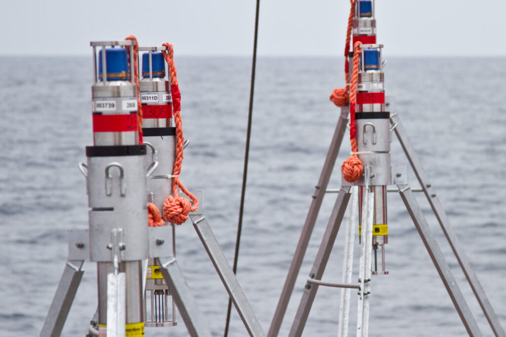
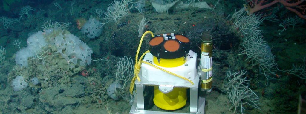
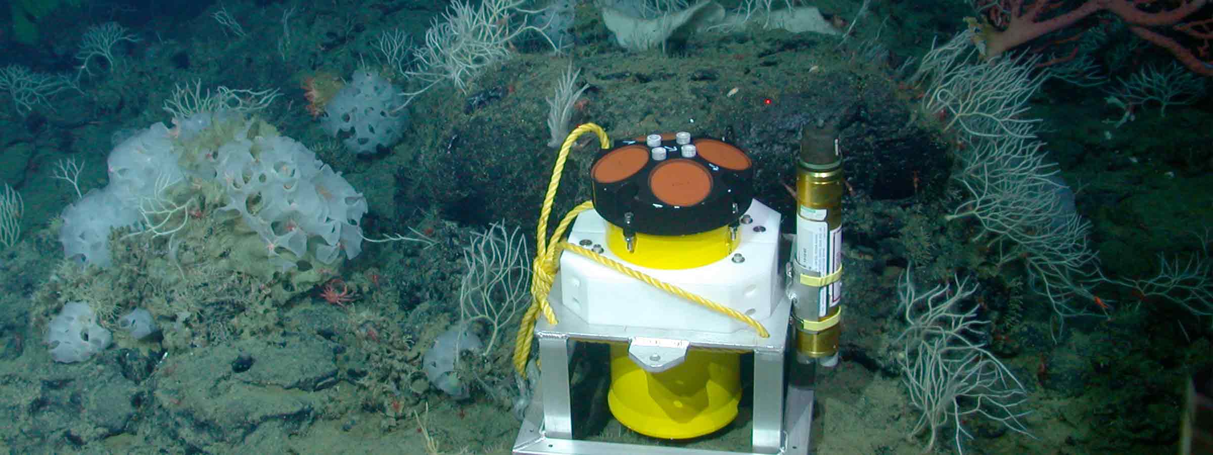
In response to this challenge, Sonardyne has worked with a number of research institutes, including GEOMAR, to supply networks of Autonomous Monitoring Transponders (AMTs ) – seabed instruments that are capable of taking hundreds of thousands of stable, highly precise geodetic observations, safely log the data and on command, wirelessly transmit it up to the surface.

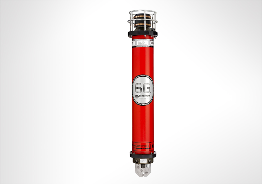
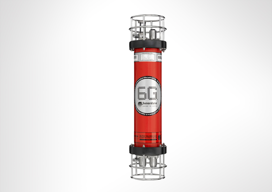
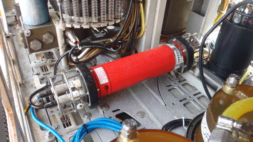
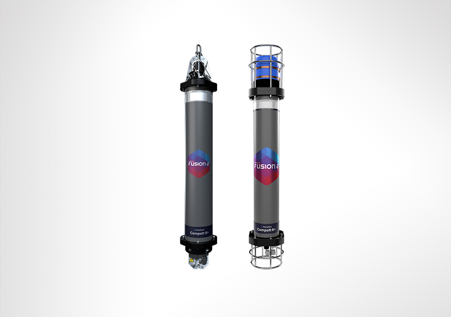
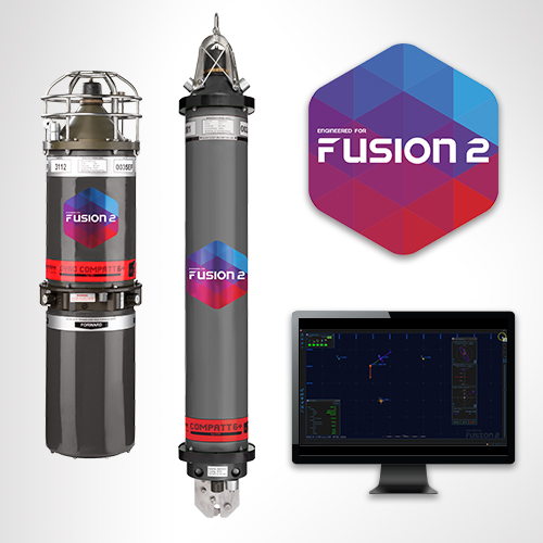
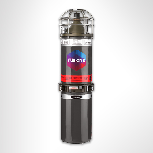
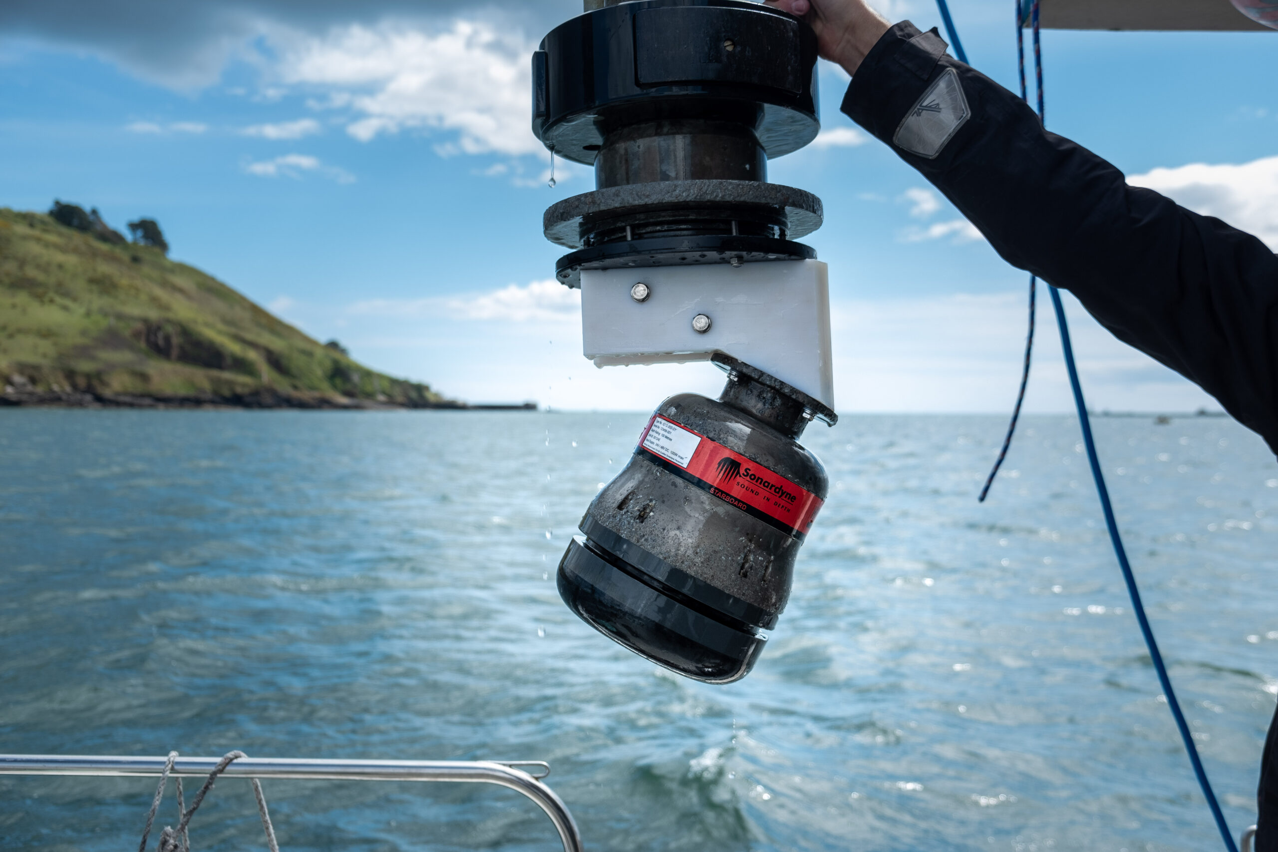
Originally developed for the offshore industry to precisely measure vertical and horizontal seabed displacements caused by reservoir depletion, AMT is a long-life (up to five years depending configuration), deep-rated acoustic instrument fitted with high resolution pressure, sound velocity and temperature sensors. All of this is built around our 6G hardware platform and Wideband 2 digital signal technology.

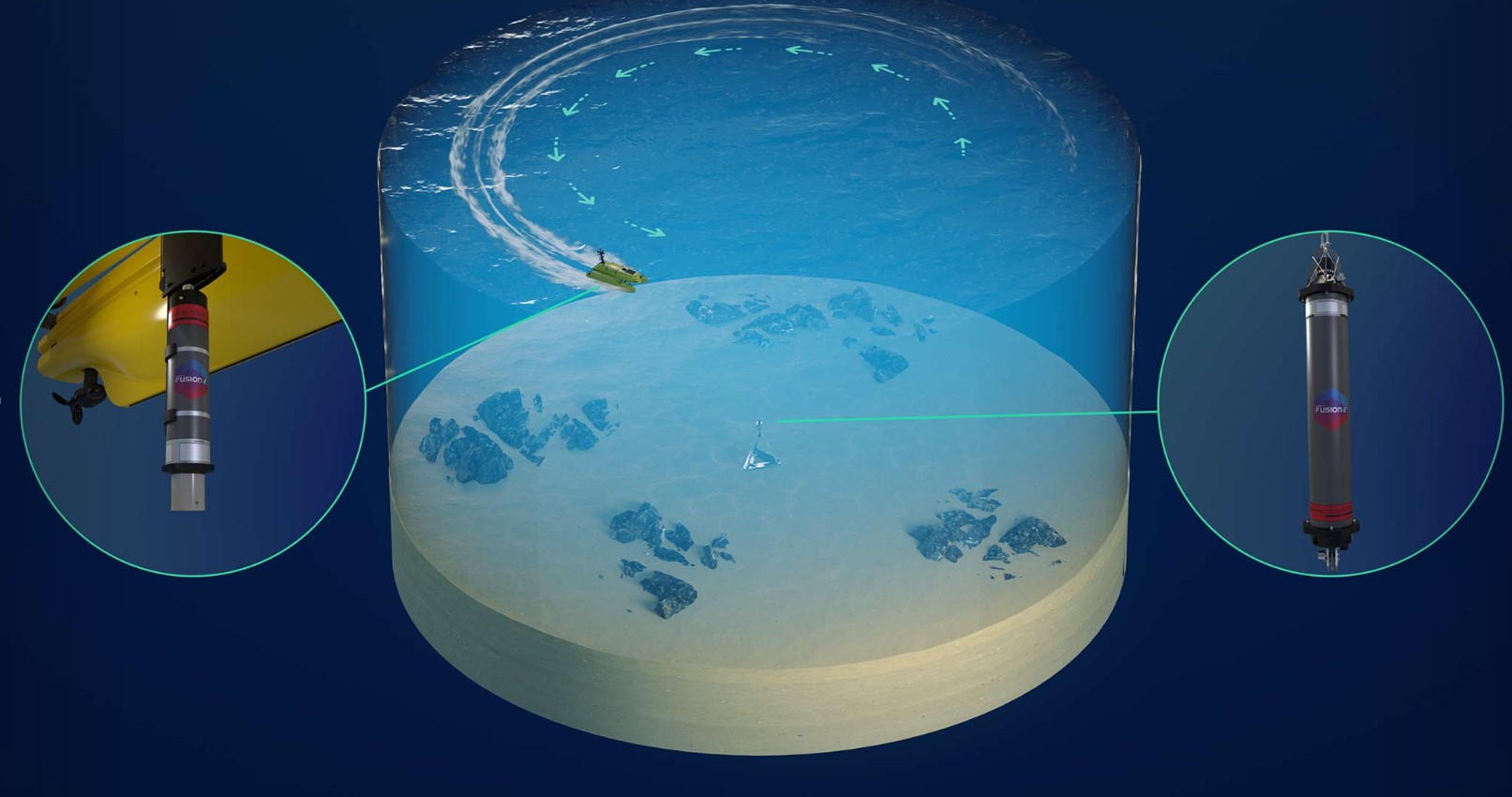
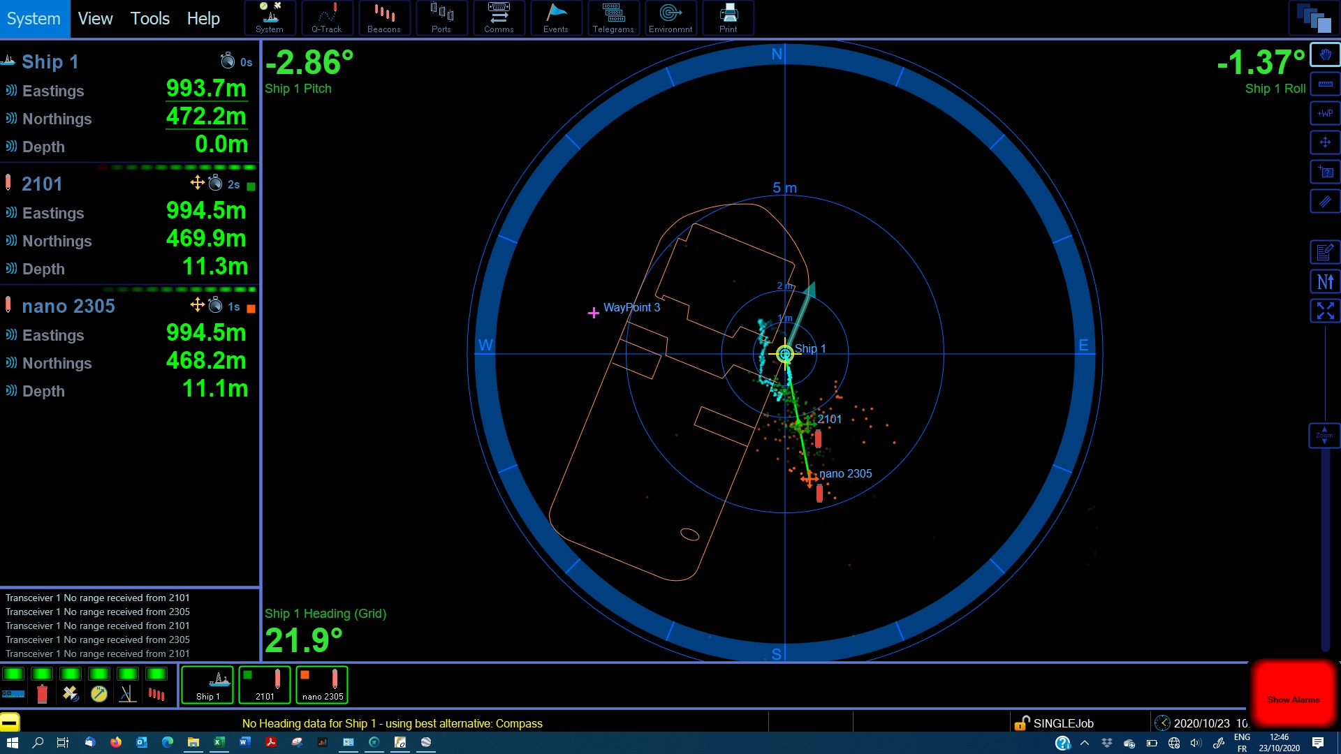
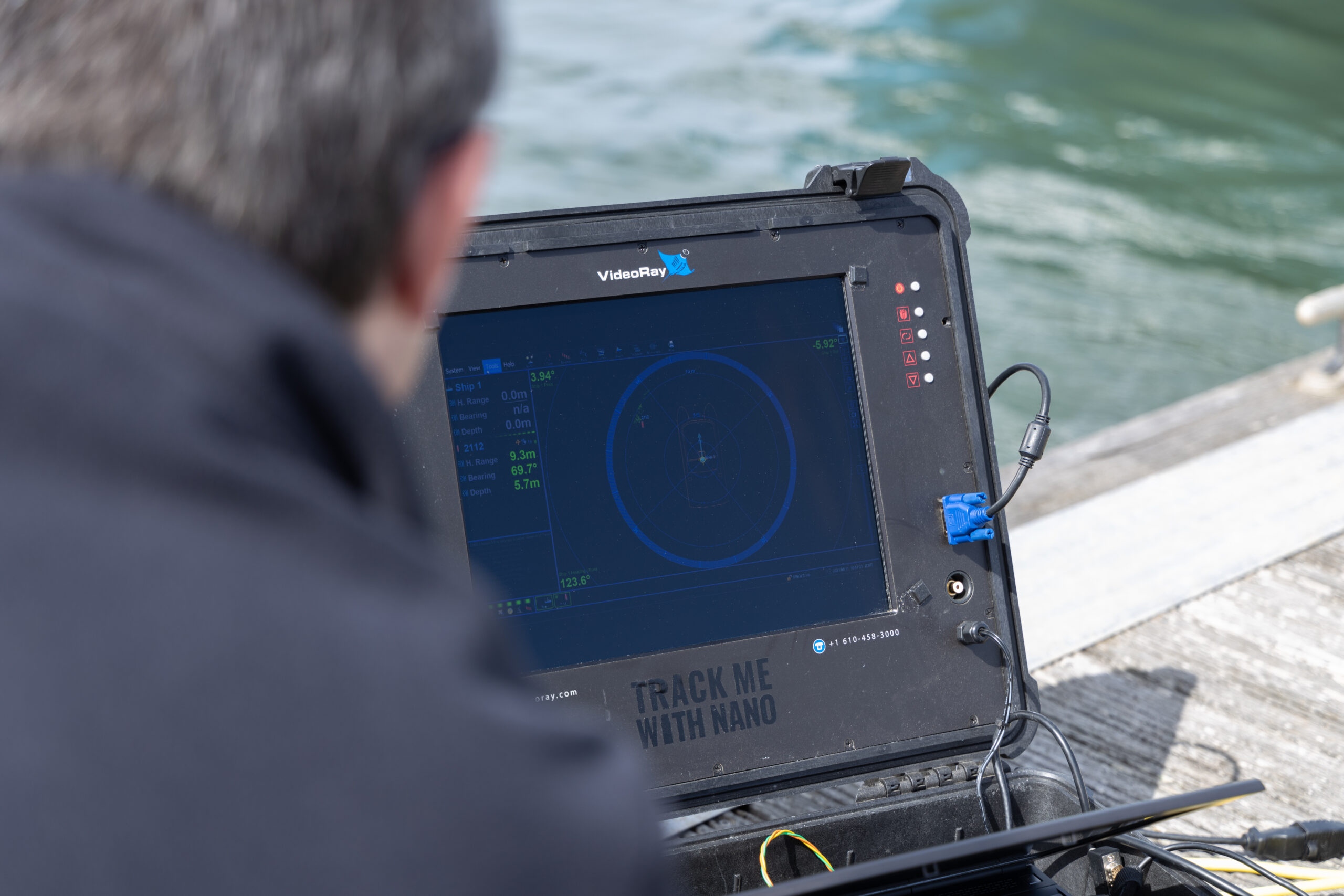
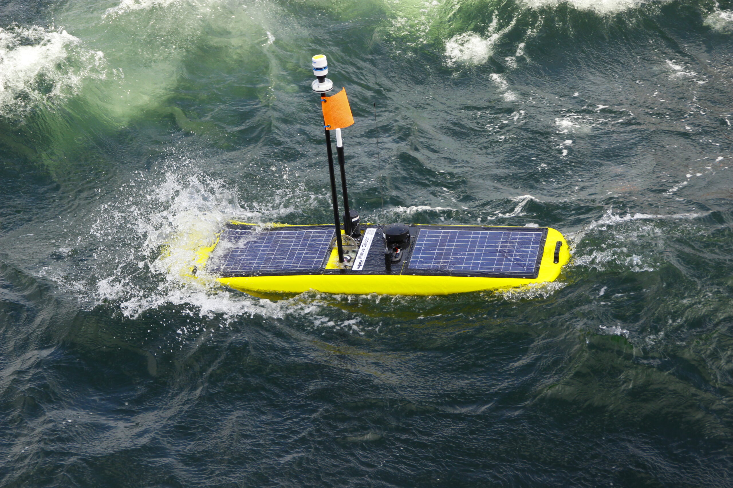
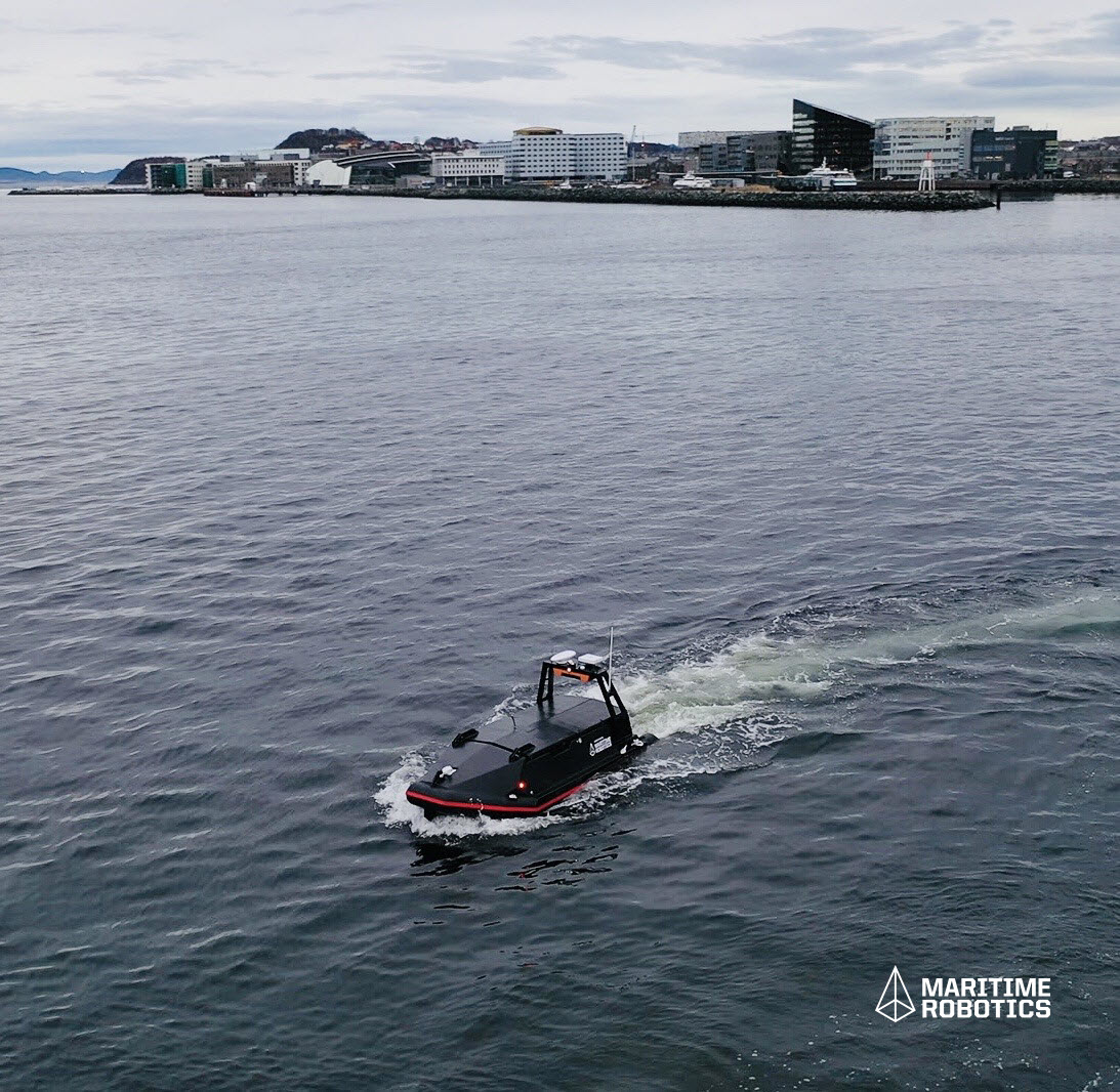
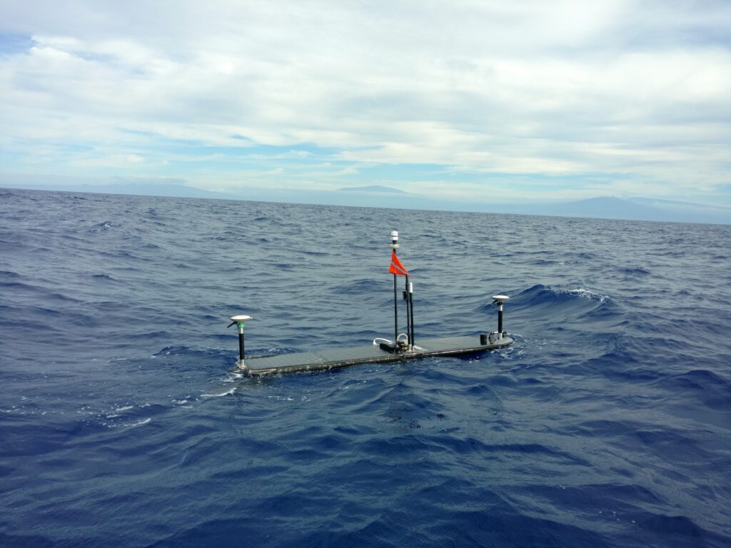
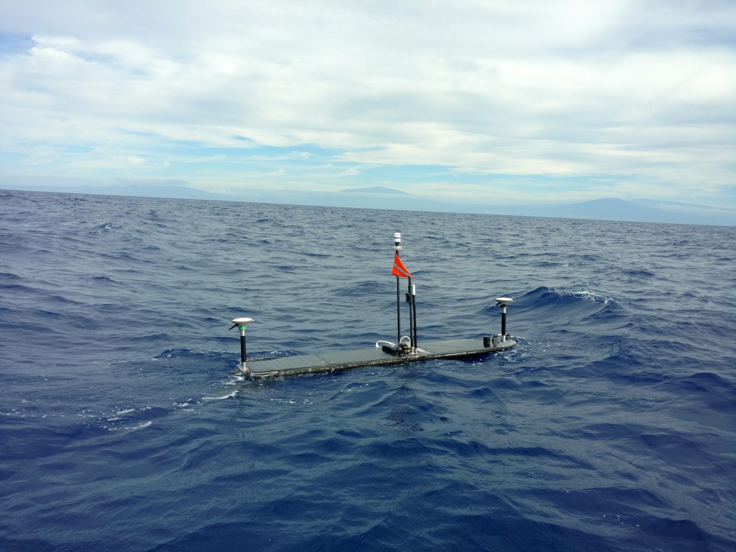
AMTs run a fully automated logging regime gathering acoustic travel time (range) between neighbouring units, pressure, sound velocity, temperature and tilt data at intervals defined by the user. A passing AUV, vessel of opportunity, gateway buoy or unmanned surface platform can harvest data on demand and at any point, the user may amend the logging regime of any or all of the AMTs, using the bi-directional communications link.

GEOMAR have now deployed three AMT seabed arrays in Chilean seas. The largest array is the Geodetic Earthquake Observatory on the SEAfloor (GeoSEA) project, offshore northern Chile on the Nazca-South American plate boundary.

The last rupture resulting in a major earthquake at the array location was in 1877. This was identified as a seismic gap prior to the 2014 Iquique/ Pisagua 8.1 magnitude earthquake.

Nevertheless, the southern portion of the segment remains unbroken by recent earthquake activity and so, with the two plates converging at a rate of around 65 millimetres per year, new tension is being continuously built up. ‘Therefore the region is a focus site for seismologists to understand strain build-up prior to an earthquake,” says Professor Kopp

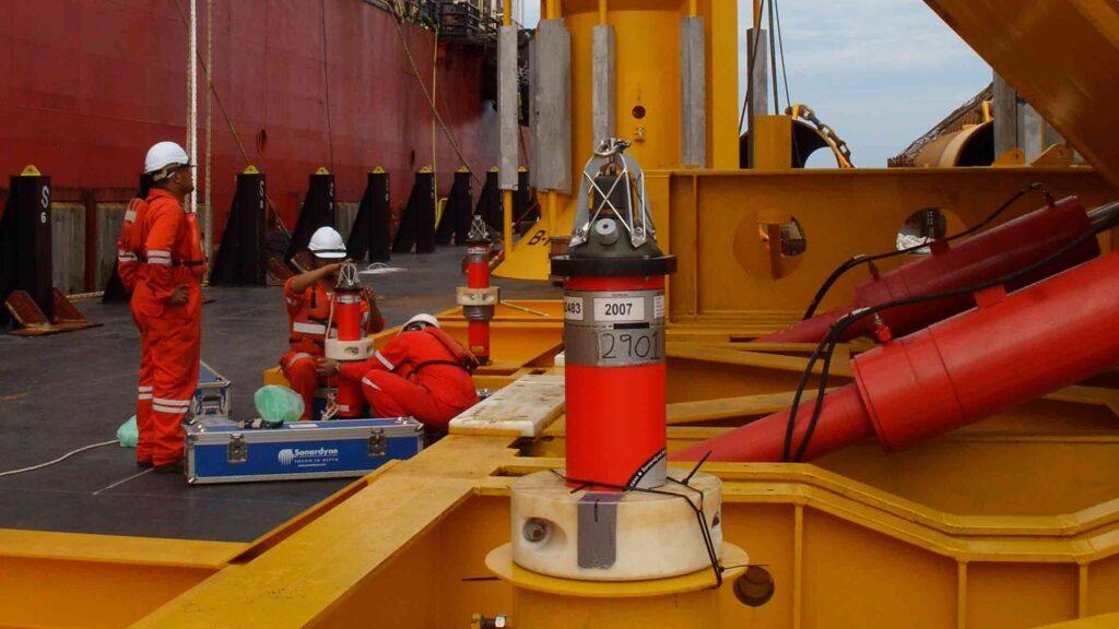
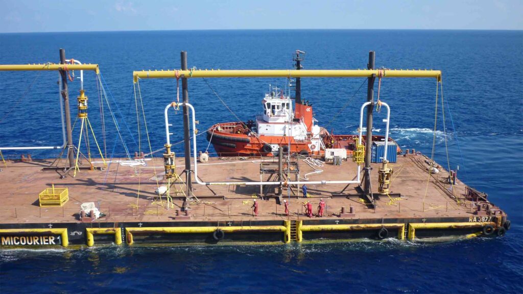
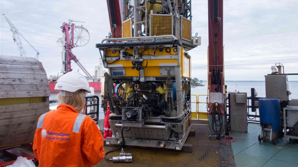
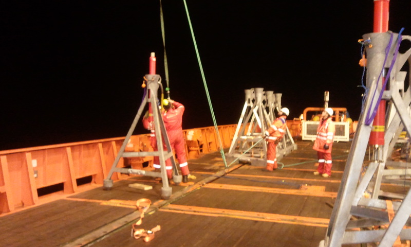
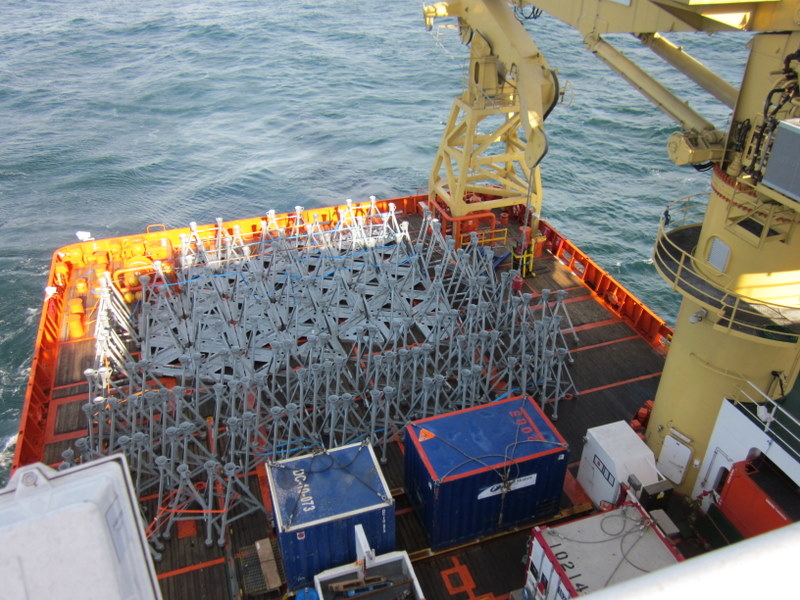
The GeoSEA array consists of 23 AMTs deployed from the German Research Vessel Sonne in late 2015 and comprises three sub-arrays that monitor different sections of the megathrust. The tectonic nature of the seabed gives rise to a variety of complex topographies.

Sonardyne’s in-house Survey Support Group worked closely with scientists from GEOMAR to plan the subarray layouts. Positioning of the AMTs were based on multibeam data collected during the preceding research leg. Precise placement in the order of a few tens of metres was required and in one case, an AMT had to be sited on a ledge on the side of a ridge that was only 50 metres wide and 150 metres long.

The first area is located on the middle continental slope between the main trench and the Chile coast and consists of eight transponders laid in pairs on a stairway-like feature of four topographic ridges at a depth of around 2,800 metres. The ridges, which are surface expressions of faults at depth, are approximately 100 metres high with around an 800 metre flat area between.

On the opposite (seaward) side of the trench from Chile, a further five AMTs were deployed in depths approaching 4,100 metres to monitor extension across plate bending related normal faults. Here, faulting of the Nazca Plate is caused by stretching of its surface as it is pushed downwards under the South American plate, and thus the fault lines are relatively new and active. The AMTs were laid at the intersection of multiple fault lines separating three or four blocks, with two being placed on the same block to provide a sound speed reference baseline.

The deepest area, located between 5,100 and 5,400 metres deep, is on the lower continental slope and comprises a circular pattern of eight AMTs surrounding two central instruments. This pattern provides a variety of short and long baselines to measure diffuse strain build-up in a highly faulted area made up of separate geological blocks, which are under high compression.

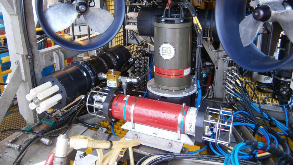
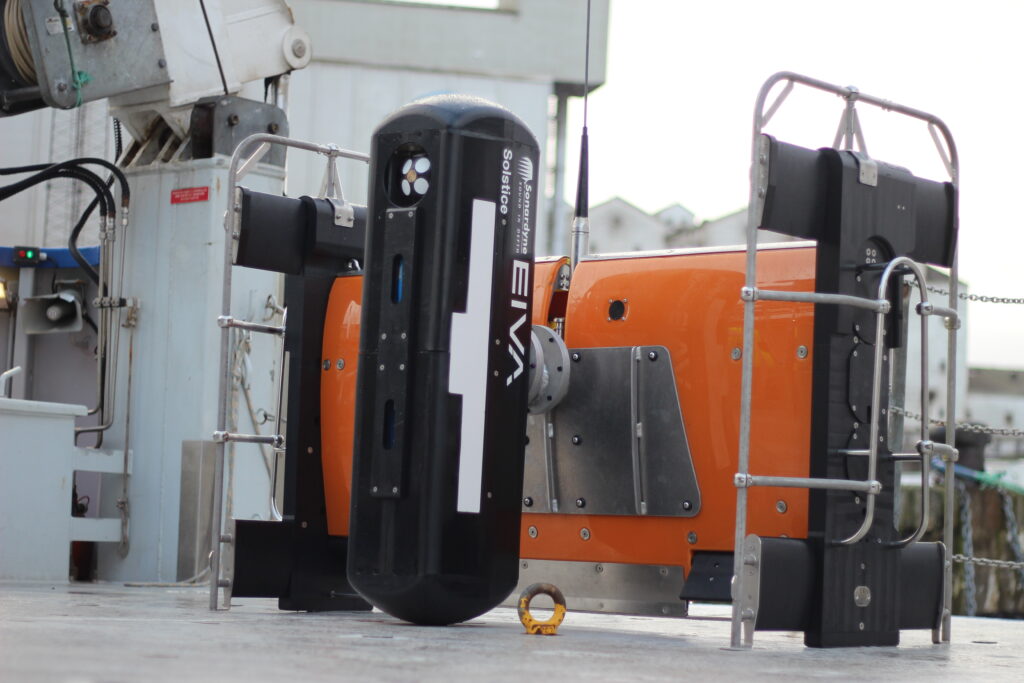
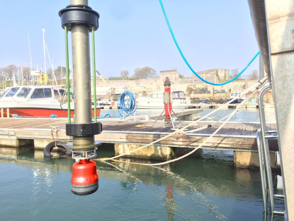
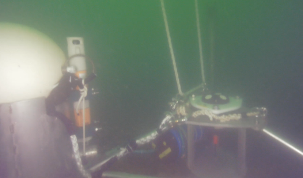
To cope with these extreme conditions, the AMTs used for the GeoSEA project are 6,000 metre-rated Lower Medium Frequency (LMF 14-19 kHz) omnidirectional units. Sampling at rates between one and a half and three hours, the GeoSEA AMTs are planned for an initial three and a half year deployment. However, the four metre high seabed frame in which each unit sits enables it to be easily removed by ROV, returned to the surface to allow its battery to be exchanged then placed back in the frame in the same position – giving scientists the option of extending the survey if required.

The results

Since initial deployment, data from the array has been recovered by a US research ship using a Sonardyne HPT 7000 dunking modem deployed over the side, as well as GEOMAR’s GeoSURF Wave Glider, equipped with a 6G acoustic communication module fitted in its hull.

“Overall, our experience with Sonardynes instruments is superb and our results have been beyond our expectations. It has been a pleasure for us to work with infrastructure that we can fully rely on.” Professor Kopp from GEOMAR commented.

The success of the AMT’s performance in the Nazca-South American plate boundary arrays has resulted in two smaller arrays in the Sea of Marmara off Turkey and on the submerged flanks of Mount Etna. Although the results of these surveys were yet to be published at the time of writing, scientists were excited by the new opportunities Sonardyne’s technology offers.

GEOMAR’s Doctor Dietrich Lange summarises that, “With this approach, we are taking a new path in earthquake research since previously, measurements of a few millimetres, were hardly possible.”

Seismic operations in the transition zone

When seismic operations move into very shallow waters, accurately positioning seismic nodes or ocean bottom cables (OBC) on the seafloor can pose a challenge.

The challenge

The transition zone environment is often highly reverberant, the vessels used are often noisy and they can be a considerable distance from the acoustic transponders used to position the nodes. What’s more, shallow water makes nodes especially prone to movement, adding a further complication to proceedings.

Repeated node positioning operations conducted from vessels are costly and time consuming. Noisy environments can inhibit the quality of information and manned vessels are a costly option for completing work that can be done remotely.

The solution

To solve these issues, Sonardyne has created our TZ Transceiver. It’s very compact and simple to operate. Ideally suited to installation on manned workboats and USVs, it’s already being used for conducting acoustic positioning operations with seismic nodes deployed in the transition zone.

The TZ Transceiver works by collecting hundreds of acoustic ranges from transponders such as our TZ/OBC, TZ Transponder and Small Seismic Transponder 6. These are often attached either directly to the seismic node or to a deployment rope nearby. The ranges are merged with the vessel or USV’s GNSS data so that an accurate position of each node can be calculated.

Mounting our TZ Transceiver onto a USV is ideal because it can follow the mother vessel autonomously and position the nodes as they are being deployed. Alternatively, it can be tasked to perform a position verification check to ensure the nodes have not moved.

The results

Fitting a TZ Transceiver to a USV such as the installation on Maritime Robotics’  Mariner USV is a very cost-effective force multiplier. The addition of the transceiver eliminates the need for a manned vessel to conduct the same routine operations.

Weighing in at 1,900 kg, Mariner is 6 m-long, 2 m-wide. It includes a moon-pool and an elevator mechanism for sinking and lowering sensors, such as our TZ Transceiver.

The vehicle is designed for both offshore and coastal applications and can be deployed and operated from a larger manned vessel or even over the horizon from a shoreside office. This increases the productivity of the existing survey crew as well as the overall profitability of seismic operations.

GPR – Acoustics unlock a new approach to seabed geodetics

Autonomous and uncrewed marine platforms are transforming the way in which we acquire and analyse data from our oceans. Our technology is assisting with seafloor geodesy, an emerging scientific field that is making the real-time study of continental plate tectonics a cost-effective and viable option.

The challenge

Seafloor geodesy projects are underway across the globe, all in pursuit of a better understanding of earthquakes, tectonic processes and tsunami hazards, and ultimately to save lives. In addition, the technology is being applied within the offshore oil and gas industry to mitigate risk through better ongoing surveillance during the producing life of a field.

But tracking seafloor and oilfield infrastructure movement at minute scale resolution through two miles of seawater is far easier said than done. Delivering the results straight to an analyst’s desk anywhere in the world takes a little more know-how than the GPS and laser methods we are used to seeing on terrafirma.

The satellite-based GPS and laser methods used on land don’t work in the ocean, so researchers are turning to a technique that’s referred to as GPS-Acoustics (GPS-A). While it’s possible to do these surveys using a vessel, unmanned surface vehicles (USV) like the Liquid Robotics Wave Glider and long endurance Sonardyne surveillance technology offer a more cost-effective solution to making GPS-A measurements.

To be able to accurately position a subsea transponder, you must first be able to accurately position the USV. This can be cost-inhibitive when it comes to academic studies. Similarly, oilfield asset monitoring becomes costly and impractical when relying on a combination of manned and unmanned vessels for visual observations and creep measurement.

Gathering seabed geodetic data is difficult, slow, expensive and not without risk to the people sent out to get the job done.

The solution

With long endurance instruments, such as Sonardyne’s Ambient-Zero-Ambient (AZA), which overcomes the inherent problem of pressure sensor drift, and a Wave Glider at the surface to position the transponders and transmit the data, there is now a viable alternative that provides near real-time awareness of plate tectonic activity.

Sonardyne’s Autonomous Monitoring Transponder(AMT) instrument is designed to autonomously and precisely measure horizontal and vertical displacement using thousands of range (distance between pairs of transponders), pressure (depth), sound velocity, and inclination measurements. Each unit runs a fully automatic data gathering and logging regime and can remain continuously deployed for up to 10 years.

Throughout a mission, the Wave Glider GPS-A payload records GPS logs in Receiver Independent Exchange (RINEX) format; a data interchange format for raw satellite navigation system data. This is a critical and unique part of the system’s ability to achieve millimetric precision.

By taking the GPS RINEX files and post processing this data with the corrected orbital paths of the GPS satellites themselves, it is possible to reduce the Root Mean Square (RMS) of the positioning by up to 30 times compared to typical GPS receiver accuracy.

Table 1 shows an Easting and Northing position scatter plot for an unmanned surface platform before (blue) and after (red) GPS-A post processing. The data was captured during a trial at Sonardyne’s research facility in Plymouth.

Similarly in Table 2, the plot shows a surface height comparison over a complete tidal cycle. Once again, the data in blue shows the raw observations, whilst the data in red provides the RINEX post processed results.

With these advances in technology, seafloor geodesy projects have sprung up around the world, in particular around the Ring of Fire in the Pacific basin where some of the most powerful earthquakes originate.

Study of the Cascadia Subduction Zone, research into the workings of the Mentawai Seismic Gap and geodetic observations of the Nazca-South American Plate Boundary are all using technologies developed by Sonardyne and Liquid Robotics.

Dr. David Chadwell of Scripps Institute of Oceanography selected Sonardyne’s Fetch instrument for the seabed component of his study of the Cascadia Subduction Zone. The Fetch has functionally equivalent to the AMT but with a much bigger battery that enables 10 year deployments. This has provided a more cost-effective platform to collect data. Their original plan to use a diesel powered buoy was also upgraded when the advantages of the Wave Gliders in terms of mobility and longevity were recognised.

Studies of the Mentawai Seismic Gap by Dr. Sylvain Barbot, Dr. Emma Hill, and Dr. Sharadha Sathiakumar of the Earth Observatory in Singapore, is being supported by quipping Wave Gliders with GPS-A technology. This is enabling them to monitor seafloor deformation off the coast of Sumatra. An unmanned platform is essential, as regular surveys using research vessels are just too expensive.

The Nazca-South American Plate Boundary has had a seafloor geodetic network of AMTs installed at key points ranging in depth from 2,600 – 6,000 metres. Rather than using absolute GPS-A measurements, the relative movement of the AMTs to each other is measured using the on-board pressure sensors and acoustic ranging between the AMTs.

The other key component of the Nazca-South American Plate Boundary network is a GPS-A equipped Wave Glider. Operating autonomously at the surface, the vehicle holds position above the seafloor stations, monitors system health, uploads data from the seafloor node, and transfers it back to shore via satellite – allowing the research vessel to focus on other more valuable tasks and facilitating the cost-effective retrieval of data from the seafloor.

The results

The impact of the technologies developed by Sonardyne and Liquid Robotics goes far beyond simply providing a cost-effective alternative to crewed vessels. As researchers pursue breakthroughs in earthquake and tsunami early warning systems, platforms like USVs may ultimately save lives.

These solutions are proven and ready for deployment today. Already they are broadening our knowledge of the deep ocean, geodetic data and the seismic relationships that impact coastal populations and oilfield asset monitoring.

Measuring Mount Etna – an underwater monitoring first

A network of Sonardyne instruments deployed by scientists from GEOMAR Helmholtz Centre for Ocean Research in Kiel for 15 months has measured underwater slippage of the southeast flank of Europe’s most active volcano, Mount Etna.

The challenge

While satellite observations have previously shown that the flank of the volcano is slowly sliding towards the sea, until the establishment of this network, it had been impossible to confirm if and how the submerged segment was moving beneath the ocean.

Results published in the international journal Science Advances confirm that the entire flank of the volcano is in gravity-driven motion and in one event the slope slipped about four centimetres in just eight days. The risk is that sudden and rapid failure of the entire slope could result in a catastrophic tsunami in the Mediterranean.

The solution

A network of five Sonardyne Autonomous Monitoring Transponders (AMTs) were deployed in April 2016 by scientists at GEOMAR and Kiel University. The placement of the transponders covered the fault line that represents the boundary between the sliding flank and the stable slope. Three AMTs were situated on the sliding sector and the final two on the side of the fault line that was presumed to be stable.

The AMTs acoustically measure the distances between each other with a millimetric precision. This sound based underwater geodetic monitoring network, so-called marine geodesy, was a first for monitoring a volcano’s movement underwater.

Geraint West, Global Business Manager – Ocean Science told us “The AMT is a highly flexible instrument that has been used by research institutes around the world to measure seabed movements as diverse as rapid canyon turbidity flows to plate motion at deep subduction zones. This project is the first time that it has been used to measure the slippage of a volcano’s submerged flank.”

“The AMT was originally developed to measure deformation of the seabed caused by the extraction of hydrocarbons over several years.” Tom Bennetts, Sonardyne Projects Manager added.

“Sonardyne first deployed AMTs on a large project over the Ormen Lange field in the Norwegian sector of the North Sea. For that project, some 220 individual instruments were deployed. The precision and endurance required for the Ormen Lange project showed us – and others – that our AMTs are also ideally suited for scientific studies of the seabed.” Bennetts clarified.

The results

The results published in the international journal Science Advances confirm that the entire flank of the volcano is in gravity-driven motion rather than the ascent of magma. One event saw the slope slip about four centimetres in just eight days. There is a very real risk that a sudden and rapid failure of the entire slope could result in a catastrophic tsunami in the Mediterranean.

Chris Hammersley, Project Engineer – Navigation Systems for Sonardyne said “Through several projects with major AMT deployments, we’ve built up a close relationship with the scientists and engineers at GEOMAR. We’re on standby to support them remotely through AMT deployment and routine data recovery missions. From our head office in the UK, we’re able to support these projects remotely, 24/7. For the Mount Etna Measurement project, we’ve been able to advise on optimal configurations for the instruments as well as troubleshoot any issues that arise, ensuring that GEOMAR have been able to use valuable ship time on site to best effect.”

The results of the study do not allow a prediction of whether and when a rapid failure of the slope might occur. For this reason, further research into the geological processes at and around Etna and other coastal volcanoes will continue. The success of our AMT deployments at Etna has secured the future use of sound-based geodetic monitoring networks for further studies.

Read more about GEOMAR’s project here.

Recovering lost history with Mini-Ranger 2

In its working life, there were more than 2,500 Fairey Barracudas delivered to the Royal Navy’s Fleet Air Arm. That’s more than any other type ordered by the Royal Navy to date. Read how James Fisher Marine Services used our Mini-Ranger 2 USBL system to recover this piece of World War II aviation history.

The challenge

A three-seat, single engine torpedo bomber, it was launched from aircraft carrier decks during World War II, carrying their lethal load to drop on to targets. Despite the numbers that were built, none remain in the UK today, at least not in complete form. However, restoration engineers at the Fleet Air Arm Museum (FAAM) in Yeovilton are looking to change that and a chance find in the English Solent is helping them on their way.

It’s the wreck of a Mk II Fairey Barracuda, discovered in 2018 by James Fisher Marine Services (JFMS) during a UXO survey for a new 204 km long power interconnector between the UK and France as part of the Interconnexion France-Angleterre 2 (IFA2) project.

IFA2 is National Grid’s second electricity subsea interconnector to France and is a joint venture with French System Operator RTE.

The wreck is believed to be one of two Barracuda aircraft which were based at Lee-On-Solent, Gosport. Both planes suffered forced landings in the Solent during WW2, shortly after take-off from HMS Daedalus airfield. While each pilot survived and made it through the remainder of WW2, their planes remained at rest on the seabed.

A challenging acoustic environment for USBL systems

Recovery of the wreck offered a great opportunity to the Fairey Barracuda restoration effort. But, it also posed a number of challenges, not least the water depth – or rather lack of it. Lying in just 5 m, Robin Fidler, who was then Survey Operations Manager at JFMS, expected to encounter acoustic interference problems tracking his divers due to signals bouncing off the seafloor and sea surface – often referred to as multipath.

Multipath can cause a USBL transceiver at the surface to falsely detect (or completely miss) a genuine reply signal from a transponder, leading to unstable tracking performance. Previous generation USBLs were particularly susceptible to multipath and needed careful setup to overcome the problem – not always successfully.

The solution

JFMS chose our Mini-Ranger 2 USBL system for the project. Mini-Ranger 2 is our mid-level USBL target tracking system. It provides shallow water performance without the cost and complexity of a deep water USBL solution. It’s also portable and quick to mobilise; a great choice for small survey vessels, moored barges and uncrewed vessels.

Six divers were used on the three-week project from the Stour jack up barge, with one diver in the water at any one time. The barge itself was fitted with an HPT 3000 transceiver mounted to the side, cabled back to a survey shack where the diving operations were controlled from.

WSM 6+ transponders fitted to each diver’s cylinder enabled the HPT to track every moment of their dive, providing a valuable layer of safety to the operation. Each diver also carried one of our Nano transponders in their pocket, this was used to place directly on top of any archaeological finds, so that precise waypoints for each artefact they discovered could be logged (and individually named) in the Mini-Ranger 2 USBL software. This information is then available for offline analysis.

The Mini-Ranger 2 USBL uses Wideband 2 for digital signal processing, so multipath never became an issue for the recovery operations, regardless of the depth of the tide. This had the additional benefit of freeing up users to deploy our USBLs virtually anywhere.

The results

The crash site was heavily silted so it needed to be cleared away for sections of the aircraft to be lifted out of the water. Artefacts retrieved included one of the pilot’s boots, a boost gauge and the underwing pitot head and mounting bracket – a delicate instrument that was used for recording the aircraft’s airspeed. The fact that this was found intact implies that the Barracuda was almost at stalling speed by the time it reached the water, says Wessex Archaeology’s Senior Project Manager Euan Mc Neill.

“We were really impressed with just how Mini-Ranger 2 operated,” says Fidler. “We thought we were going to have to use a (Fanbeam) laser radar system, tracking a reflective buoy attached to the diver to give us a range and bearing to the diver. We didn’t have to use it once; we could do it all with USBL, no matter what the tide, which made our lives much easier and that’s all we could ask. The USBL didn’t miss a beat. We were up and running with it quickly meaning that we were able to maximise the three week window we had on site.”