ROAM is a small box that provides a secure remote internet connection to allow Sonardyne engineers access to the vessel’s systems.
It is usually used for remotely connecting to an offshore system or network that would normally be too risky to connect online. The link is provided via the vessel’s satellite connection or a local mobile telephone network, when in range.
Typically, critical vessel systems, such as acoustic positioning systems, would not be connected to the internet as it can be difficult to manage system updates, and there is a risk that uncontrolled updates to the operating system or antivirus software may impact on the navigation software. That in turn could impact on the vessel’s operations. Not updating these can leave the systems vulnerable to viruses or the ever-increasing risk of being hacked. So, there is a catch 22, with the choices being a lack of change control, versus being hacked, picking up a virus or being held to ransom by malware. Malware attacks have in recent times grounded whole fleets of vessels.
To overcome this, ROAM contains a hardware firewall and VPN (Virtual Private Network), which allows the system to be connected to the outside world, without being online in the conventional sense. The firewall prevents access directly from the internet, keeping hackers and viruses at bay, while the VPN provides a secure tunnel through the firewall to a Sonardyne engineer. This single box solution allows our engineers to view or control the PC while reducing the risks normally associated with being online.
As a result, ROAM will allow Sonardyne engineers secure access to our systems on vessels to enable us to provide software or firmware updates, monitor or control operations remotely, or provide first hand system set-ups and health checks.
Contact [email protected] for more information.
This article describes how to bleed air from our standard Through-Hull Deployment Machine.
This normally only needs to be done once, at the commissioning stage following installation.
Having a properly-bled system improves system performance. In some instances, bleeding the system is the cure for old, rarely-used machines.

Procedure
- Start with the pole at the top position, with the locking pin in the gantry hole, as shown in the image above.
- Ensure the HPU tank is filled with hydraulic oil just above the Max level of its glass gauge.
- Disable the top sensor, so that the TOP light does not illuminate; see Note below.
- Press the UP button.
- Make sure the locking cylinder pin fully retracts.
- Hold the UP button for about 30 seconds.
- Release the UP button and immediately press the DOWN button (so that the pin does not have chance to retract until the pole is below the gantry hole).
- Release the DOWN button when the pole has been lowered below the hole.
- Enable the top sensor.
- Press the UP button until the flag reaches the sensor, and check that the pole automatically stops, and the pin extends into the hole.
- Top up the tank if required.
- Exercise the pole up and down a few times.
- Top up the tank to its maximum level with the pole at its top position.
Note
Disabling the top sensor can be performed in a number of ways. Choose one of the following methods:
- Bend the sensor flag outwards a small amount, so that it fails to activate the proximity sensor.
- Remove one of the supporting bolts and loosen another, so that the sensor flag rotates downwards, thereby again failing to activate the proximity sensor.
- Remove the wire from terminal 10 (from any side of the terminal block, whichever is easier) inside either the Local Control Unit or the Main Control Unit.
Follow the connection and operating procedure steps below for RT 6-1000.
Equipment Required:
- Sonardyne NFC module (part number: 265-7020)
- Sonardyne NFC configurator software
- RT 6-1000
- RT 6-1000 User Manual
Procedure:
1. Open the NFC configurator software.
2. Confirm the Connected status is reported.

3. Connect the RT 6-1000; ensure the RT 6-1000’s transducer is positioned directly on or just above the NFC module. The NFC configurator software will automatically connect to the RT 6-1000 and will display either DISABLED or ENABLED with the beacon information.


The RT 6-1000 will emit a beep when the Enable/Disable button is selected, and the mode of operation is changed.
Sonardyne strongly recommends the RT 6-1000 should be set to Disabled, unless on operations.
4. Prior to deployment, and as part of the deployment and recovery procedures, it is recommended to enable the RT 6-1000 and record the following information:
- UID
- Serial number
- Address
- Battery voltage
- Batter capacity
5. Complete a Self Test by clicking Self Test. If it passes, the NFC Configurator will display Self Test Successful.

6. Change the RT 6-1000 address (if required) by clicking Select Address (if you need to change the address, it is strongly recommended to note the original address and new address prior to deployment).

8. Send a manual command (as needed) by clicking Manual CMD.
Sonadyne strongly recommends the manual command should not be changed or modified.
The limited available commands are:
- FS – Fixed Status displays the address, UID, firmware, transducer type, power level, inclinometer status
- CS – Configuration Status displays the address and power level
- VS – Volatile Status displays battery information
Note: these commands are automatically sent during the initial communication and displayed on the Manual Command window.

Follow the steps below to help us resolve any general issues with your SPRINT, SPRINT-Nav, Lodestar and Lodestar-Nav instruments.
When reporting installation or operational issues, please provide the following general information for the Sonardyne equipment:
- Serial numbers.
- Firmware versions.
- Software version.
- How is the Sonardyne equipment mounted on the subsea vehicle? Any pictures would be extremely useful.
- Confirm you have checked all subsea connectors and wiring? Wiring diagram would be extremely useful.
- Detailed report of the operational issues encountered listing the date and time when the issue was first reported.
- Troubleshooting procedures, you have already completed. Have you reviewed “Fusion 2 Troubleshooting and FAQs” in the Fusion 2 use manual and/or “Troubleshooting for SPRINT” in the SPRINT-Nav user manuals?
- If this is a Fusion 2 operational issue, please send in the files listed in “Data Logging and Export” of the Fusion 2 user manual and INS bin files . If this is a SPRINT software issue, then send in the INS .bin files directly from the SPRINT-Nav unit as listed in “Retrieving On-board Log Files” of the SPRINT-Nav user manual or from (C:\Users\Public\Documents\Sonardyne\Hub\Logfiles). If possible, the .bin files sent in should be approximately one hour prior to the reported issue and one hour after.
- Send the information to [email protected]
This article describes the Sonardyne Through-Hull Deployment Machine and the installation procedures.
Description
Our Through-Hull Deployment Machine is described below.

Our standard model typically extends the pole so that the face of an attached Transceiver is about 2‑3 m below the hull.
We can also supply longer versions to accommodate deeper penetrations, or to overcome double-skinned hulls, or shorter ones where installation space is a premium.
These types of machine have been supplied to vessels of all sizes and types all over the world since 1996.
The Deployment Machine sits on a Gate Valve, and with the Gate Valve open, an operator can press a button from one of the available control panels, and the pole will move downwards.

Another button will move the pole up again.
Typically mounted on the end of the pole is our HPT Transceiver or Gyro USBL.
When in dry dock, this is easily serviced by deploying the pole through the hull.

At sea, with the Gate Valve closed, the Sea Chest can be drained, and then opened to gain access to the Transceiver/GyroUSBL.


Sometimes it will need cleaning, so it’s a good idea to inspect it now and again.

The machine is hydraulically driven from a Hydraulic Power Unit (HPU).

Control Panels
Control panels provide the user-interface, in order to lower and raise the pole, and – if a Hydraulic Actuator is fitted – open and close the Gate Valve.
This is the Main Control Unit.

This is the Local Control Unit, which is intended to be mounted inside the cofferdam, next to the Deployment Machine for commissioning purposes.

This is the Bridge Panel Assembly, which is often the preferred Bridge control device.
We also provide a Bridge Control Unit (similar to a Local Control Unit) for wall-mounting.

Bridge Panel Assembly
Here’s the Bridge Panel Assembly fitted.

HPU and Main Control Unit
The HPU and Main Control Unit should be mounted close to each other, but outside the cofferdam.
A water-tight cofferdam is the preferred location for the Deployment Machine, so that if it floods, at least only the Local Control Unit will be sacrificed.
The HPU has a hand pump, and in an emergency, and for some commissioning activities, this can be used to manually pump the pole up and down – and if a hydraulic actuator is fitted – pump the Gate Valve open and closed.

The new IDEC SmartAxis PLC introduced into the new Main Control Cabinet in July 2016, provides an RS485 interface, which can be used to control the Deployment Machine (and Gate Valve Actuator if fitted) via software.

Ranger 2 and Marksman
This is how it looks in Ranger 2 or Marksman.

Installation
Let’s look at a typical installation.
First of all, a suitable hole is cut in the hull of the vessel.


The vessel supplies a through-tube penetrator pipe, which is used to penetrate the vessel hull.
The Weldable Flange (which we supply) is welded to the through-tube penetrator pipe, and the Gate Valve will sit on top of this flange.


The length of the through-tube penetrator pipe should be kept to a minimum – typically 150-300 mm.
This provides adequate space to install the Gate Valve fixings but does not impact on the overall depth to which the transceiver will be deployed. A reduction in the deployed length could impact on the acoustic performance.

The through-hull pipe must have adequate internal diameter for the required sensor, as shown in the table below.
| Sonardyne Instrument | Unit Diameter (mm) |
| HPT 2000 | 234 |
| HPT 3000 | 234 |
| HPT 5000 | 225 |
| HPT 7000 | 310 |
| Gyro USBL 5000 | 225 |
| Gyro USBL 7000 | 310 |
| Sentinel | 330 |
It is advisable to have rigid straffing stakes around the through-tube penetrator pipe, to ensure a sturdy base for the Gate Valve and Deployment Machine.
This also helps take the strain when the pole is deployed, and can be vital in cases where the pole is accidentally left deployed and the vessel runs aground.
In such cases, a poorly-supported penetrator pipe could rupture before the pole bends, and cause serious flooding to the cofferdam.

The Gate Valve sits on top of the Weldable Flange and is bolted in position, with a gasket seal between each face.
The picture below shows a DN350 Gate Valve with a Hydraulc Actuator fitted.

The Hydraulic Actuator is optional. A standard delivery would be with just a wheel to manually open and close the valve, together with gasket, fixings, and open/close proximity sensors.


Our standard size is the DN350 Gate Valve (as the name suggests, this has a 350mm internal diameter).
If the Gate Valve is to be installed some time before installation of the Deployment Machine, and the vessel is to be floated out of dry dock, then a blind flange is recommended to guard against leakage through the valve seat seal.

A Deployment Machine being prepared for installation.


Bracing is fitted to the Bearing & Sealing Section to provide a rigid foundation for the Deployment Machine.


The machine is also supported at the top.

Although not as critical as the Bearing & Sealing Section bracing, it nevertheless, assists with the reduction of vibration.
Hydraulic hoses run from the HPU: one to provide hydraulic pressure to drive the pole down; another hose to drive the pole up.

A further two hoses are required to drive the Gate Valve open and closed if a Hydraulic Actuator is fitted.
The pole automatically stops when it triggers a proximity sensor at the top of the machine.

It also automatically stops when it triggers another at the bottom of the machine.
Gate Valves use the same type of proximity sensor to determine their Open and Closed state.

The Deployment pole is held rigid at any position along its travel – accomplished by its counterbalance (overcentre) valve.
However, at its fully-up and fully-down position, a hydraulic pin pushes into a securing hole, to provide an extra element of support.
For more detailed information, see the Deployment Machine support pages.
Historically, Sonardyne supplied AODC beacons, such as the Type 7097 and 7192.
However, these are now obsolete, and Technical Bulletin, TB21-001 recommends the 3rd party RJE ATT400 Emergency Beacon.
This article describes how to track Underwater Locator Beacons (ULBs) like these.
Traditionally, an AODC Transponder is configured for either Channel A or Channel B.
Sonardyne’s now-obsolete AODC beacons utilised the following specifications:
| Channel A | |
| Interrogation | 38.5 kHz |
| Reply | 37.5 kHz |
| TAT | 125 ms |
| Pulse Length | Approximately 10 m for transmit and receive pulses |
| Architecture | Toneburst |
| Channel B | |
| Interrogation | 39.5 kHz |
| Reply | 37.5 kHz |
| TAT | 125 ms |
| Pulse Length | Approximately 10 m for transmit and receive pulses |
| Architecture | Toneburst |
Note that the only difference between Channel A and B, is the interrogation frequency.
This can be tracked from Marksman/Ranger 2 by selecting an AODC beacon.
![]()
Select either Channel A or B.
![]()
![]()
Track the beacon as normal.
Although the summary data sheet of the AT400 suggests that the beacon supports AODC Channels A & B described above, its datasheet suggests otherwise.
![]()
The configuration is selected by opening the beacon, and accessing SW1 as shown below.
![]()
Assume the beacon is set as a free-running Pinger, to transmit pulses of 33 kHz at regular intervals when its water-activated switch is enabled.
Access the Pinger Locator.
![]()
Enter the expected Pinger frequency, and assumed beacon depth below the transceiver face, and click Apply.
![]()
The beacon’s position will be displayed, together with its elevation, and received signal strength and SNR.
Adjust the Transceiver Gain accordingly.
![]()
This article explains how to compensate for responder latency.
The time between triggering a Responder from topside equipment, and the actual acoustic burst (latency) will cause a positioning error if not compensated.
This shows a normal transponder.

Select the transponder – the Beacon Specific button is not available.

Change to Responder mode.
With an NSH connected, you would normally see the NSH port.
Clicking Apply causes the CS:2709;…..,RSP1 command to be acoustically sent to the beacon (for a WSM6+, for example).

Select the Responder – the Beacon Specific button is now available.
Click the Beacon Specific button.

The following will not send any acoustic command, but instead tell Marksman/Ranger2 to allow for a 30 ms delay from the rising edge of the Responder pulse to the beacon actually transmitting its acoustic pulse.

Click OK to confirm.
In this example, in 1000 m water depth @ 1485 m/s, if the 30 m latency was not accounted for, then straight over the Responder, its depth would indicate 44.55 m deeper than it should be.
Latency can be accurately measured by using an oscilloscope to view the time between the rising edge of the electrical stimulus from topside equipment, to the actual burst of acoustic energy from the transducer.
Alternatively, with an accurate sound speed entered, and the beacon directly below the Transceiver, the beacon can be switched between Transponder and Responder mode, and latency estimated.
This article describes how to set up an SSB_LBP Telegram
Serial Comms
The SSB_LBP telegram can be configured to output a $PSIMSSB or a $PSIMLBP address depending on how the telegram is set up. By adjusting the frame of reference and orientation, it can also adjust the coordinate system and orientation information.
If using a serial connection for the telegram output, configure the telegram with the correct port, baud rate and Data-Parity-Stop.

UDP Comms
If using a UDP connection for the output telegram, the correct output mode will need to be selected for your operational requirements along with IP address and Tx port.
Broadcast will send the output telegram to the entire network where any connected receiver will be able to pick it up. This option is the most typical configuration used.
Multicast will send the telegram to a set of receivers on the network but not all.
Unicast will send the telegram to only one receiver using a specific IP address.

LBL Positioning
If the telegram is enabled for the vessel instead of the beacon(s), and the frame of reference is a beacon, the system will output an LBL type telegram.
The example below shows these details:

An example of the output string is shown below:

USBL Positioning
If the telegram is enabled for the beacon(s) instead of the vessel, a $PSIMSSB telegram will be generated for USBL positioning.
An example of setup and the telegram is shown below:


Beacon Names
Beacons are named in the telegram by using the index value on the telegram set up page. They can be numbered from 1—99. A beacon with the index of 7 for example would show in the telegram as B07.
It is imperative that the beacon is named with the correct index value as this is what the external system will use to identify individual beacons.

Cartesian or UTM
When the telegram is set up, by default it will have a World Frame of Reference along with an Orientation of North Up. This will be denoted in the output sting with ‘U,N’
If the telegram is set to World, the coordinate system used will be Geodesy UTM/WGS84. This will be marked with ‘U’ in the telegram. If it is set to the Ship, it will use cartesian coordinates which are marked by ‘C’ in the telegram.
An Orientation of North up will output ‘N’ in the telegram whereas Bow up will output ‘H’.
Supported options for NMEA SSB Telegram are shown in the table below.
| Coordinate System | Orientation | X_coordinate | Y_coordinate |
| C | H | Starboard | Forwards |
| C | N | North (m) | East (m) |
| U | N | Northings (m) | Eastings (m) |
| R | N | Latitude (radians) | Longitude (radians) |
Further information can be found in Appendix “Output Telegram Formats and Interfaces > NMEA 0183 SSB – (USBL/SSBL Position)” of the Ranger 2 User Manual.
The example below is set up to output Cartesian, Bow Up (C,H).


Contact [email protected] for more information.
This article shows you how to clean a transceiver array that is covered in marine growth or has been over-sprayed with anti-fouling coatings.
A transceiver face with typical biofouling:
![]()
A transceiver face with typical paint overspray:
![]()
Biofouling
Biofouling in particular can cause degradation in positioning performance, as it will alter the way in which acoustic waves propagate across the face of the array.
Paint Contamination
Paint contamination on the front face of the array could possibly cause significant life reduction due to incompatibility between the chemical composition of the paint and the array face material.
In both cases above it is prudent to remove the unwanted materials as quickly as possible.
Cleaning Procedure
1. Wash down the transceiver and array face with clean water and remove any loose biofouling or debris.
2. Use a plastic scraper to remove stubbornly attached marine life such as barnacles, keeping the motion of the scraper flat across the array surface. The array face does not have to be perfectly smooth when the process is finished. Sometimes it is more prudent to leave small pieces of very well attached biofouling in place (e.g. the rim of a limpet shell) and so avoid damaging the array.
Note: Do not use any form of scraper that could cause deep scratches to the array face.
3. After the worst of the biofouling has been removed, lightly hand sand the face with abrasive paper such as “wet and dry” to remove the final signs of biofouling or anti fouling paint coating. Use a grade equivalent to 240 grit with lots of clean water to keep the process wet and ensure that the sanding is carried out evenly across the whole face of the array.
4. To complete the cleaning process, lightly wipe the surface of the array using an alcohol wipe to remove any oil or grease residues.
5. Finally, carefully examine the array face for damage, such as small cracks which typically occur around the edge of where the barnacles have been attached. If there are any defects deeper than 1 mm or you have any doubts about damage to the array face, take some photographs and send them to [email protected] for further advice.
Remember, the transceiver should always be fully immersed in water in the sea chest, so after closing the sea chest door, remember to flood the sea chest by opening the upper sea chest ball valve and vent the air.
Contact [email protected] for more information.
This article describes the procedure for installing Mini- and Micro-Ranger 2 software.
Before you begin, refer to the relevant user manual for prerequisites/hardware requirements and request of copy of the release notes for the software version that you will be upgrading your system to. Confirm your PC meets all the listed hardware requirements and also confirm the HPT and ESH firmware versions; if these require updating, this can be done at a later date.
Note: Be advised that Sonardyne software is only tested and approved using an English version of Windows® 10 operating system.
Mini- and Micro Ranger 2 Installation Procedure
1. Using Windows Explorer, navigate to and save a .cef file from your current Mini- or Micro-Ranger 2 system to the PC (the .cef file stores the system and job information and can be used as a back-up if required).
2. Exit Mini- or Micro-Ranger 2.
3. Upload the software 8251-015-Axx.iso file to the Mini- or Micro-Ranger 2 PC from the Sonardyne FTP (Customer Support can supply instructions) or use the 8251-015-Axx.iso file stored on the Sonardyne supplied memory stick.
4. Exit all other software programs and if possible, temporarily stop all firewall and anti-virus programs.
5. Confirm your Mini- or Micro Ranger 2 security key is installed in one of the USB ports.
6. Uninstall the current Mini- or Micro Ranger 2 software on the PC (if this is a new install, disregard this step).
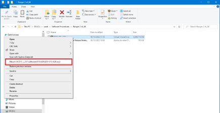
7. Navigate to the folder where the .iso file was saved in step 3. Right-click the .iso file and select Mount. This will mount a virtual drive on your PC.
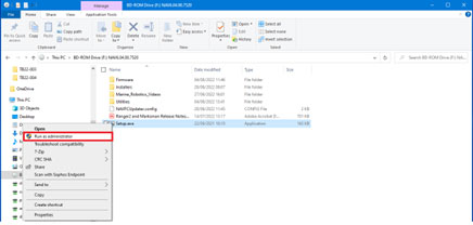
8. Right-click on the setup.exe and select Run as Administrator.
9. Continue through the installation process. If any alerts or errors are displayed, stop the installation and send relevant screenshots to [email protected]
10. When the installation process has completed, check the Mini- or Micro-Ranger 2 system starts up, connects to all external instruments and no unexpected events or alarms are reported. The software installation process should not overwrite the job or system settings. If there are any issues with the setup, please contact [email protected] who can take you through the process of recovering the information from the .cef saved in step 1.
11. If necessary, update the HPT and or ESH firmware to the versions listed in the release notes.
HPT and ESH Firmware Update Procedure
To update the HPT and ESH firmware:
1. Navigate to and locate the firmware in the Firmware folder in the 8251-015-Axx.iso file. Save these files on your PC.
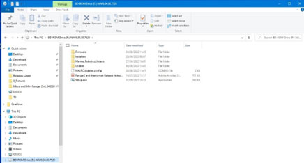
2. The Utilities folders contains the current version of user manuals which have the firmware update procedures, QSG and software programs.
Contact [email protected] for more information.