Sonardyne
Support Centre
Jump to

Overview

Intelligent monitoring for your subsea assets

Observer shows you how your subsea assets are really behaving, not how you hope they are. Monitor movement, vibration, load and structural behaviour to reduce risk, prevent unplanned shutdowns and extend asset life.

Onboard processing, extended deployment and wireless data access give you intelligence on demand, keeping operations efficient and assets protected. Subsea asset integrity intelligence delivered. Intervention and cost reduced.

Find out what's possible

We understand that no two subsea asset integrity monitoring challenges are the same

Your underwater infrastructure is subject to constant environmental and process problems, from vortex induced vibration to pressure or temperature cycling, leading to strain and fatigue accumulation. But left unseen, these can lead to unknown risks, downtime or even failure. 

Early detection prevents catastrophic failures and extends asset life. 

Observer delivers the insights you need, when you need them, preventing risk, reducing cost, extending field life. Built on decades of underwater monitoring expertise 

It’s been designed with flexibility of operation in mind; for use on all subsea assets, through the water column, including pipelines, risers, moorings, umbilicals, wellheads and associated infrastructure, helping integrity managers to reduce uncertainty and strengthen decision‑making.  

Enhanced clarity and control through real‑time intelligence

From high or low frequency motion monitoring to a wide range of other sensor data, Observer is designed for maximum flexibility and configurability, putting you in control.  

You can monitor locally or across wider areas, from short-duration campaigns to long-term integrity management. It’s non-intrusive, wireless communications make this possible. 

With standardised ROVdeployment options, you can simplify installation and recovery, onboard analytics and wireless data, get you the intelligence you need, on-demand.  

0

m

depth rating

Up to

0

years

life

0

DOF

as standard

Why choose it?

Powerful onboard analytics – you can make decisions based on real behaviour, not assumption 

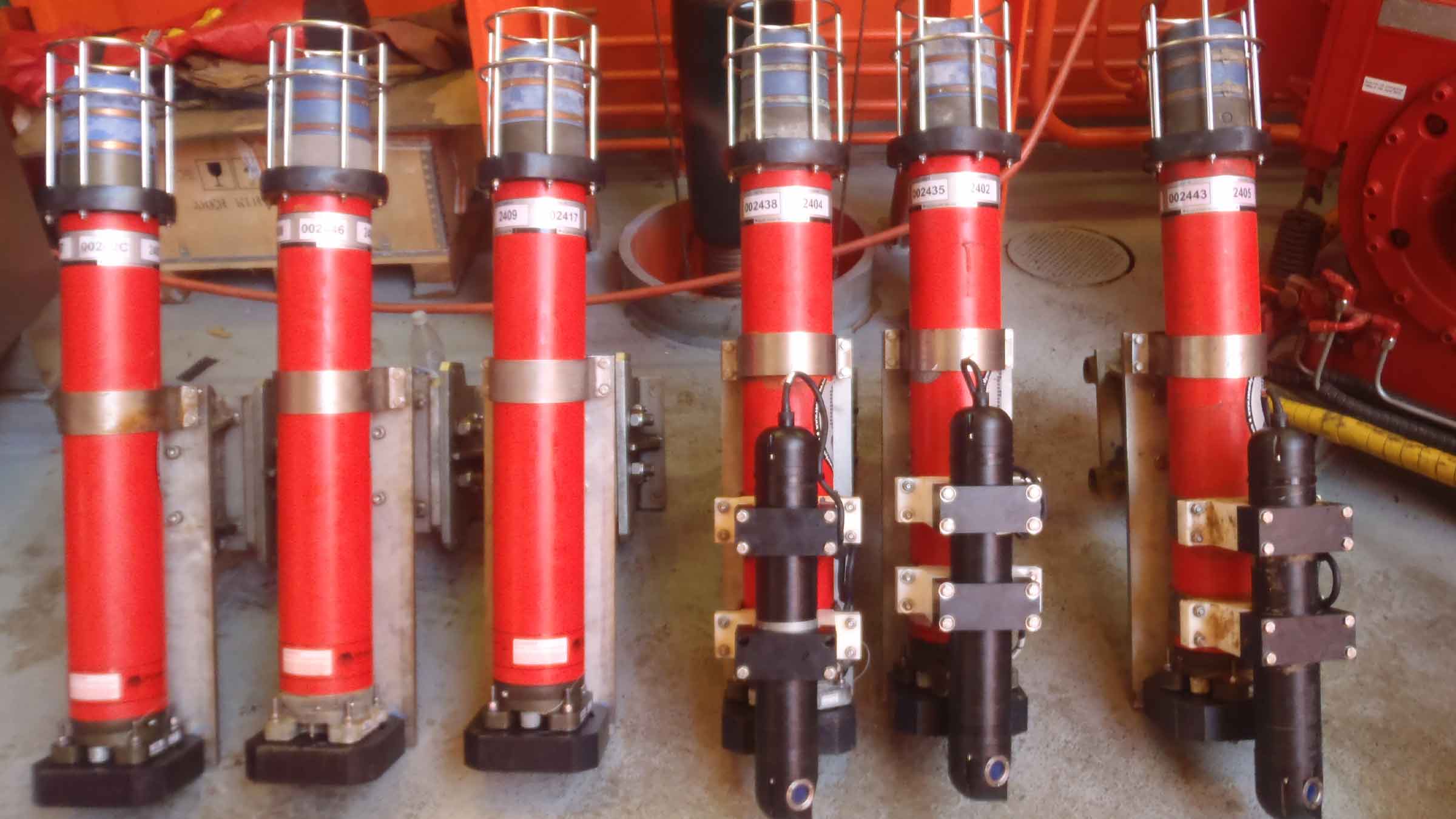
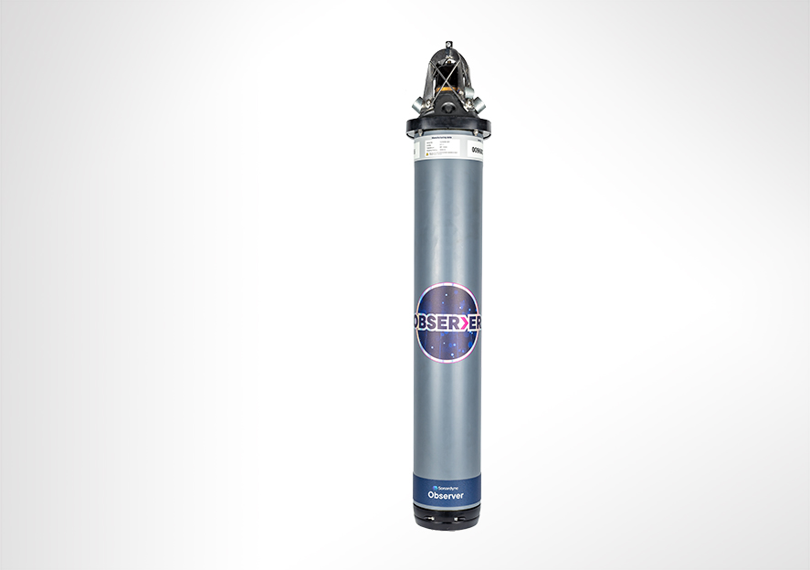
Observer contains SmartCore, our advanced, modular central processing unit. It’s the system’s brain, delivering low power and high performance that supports deployments of up to 10 years, storing raw and analysed at source. 

Apply your own algorithms or use histograms to support fatigue and damage estimation, putting analysis in your control and powering your digital twin. An intuitive, secure, web-based interface streamlines flexible configuration, driving faster decision making and lower operational costs. 

Low and high frequency measurements in one device – no need for different systems 

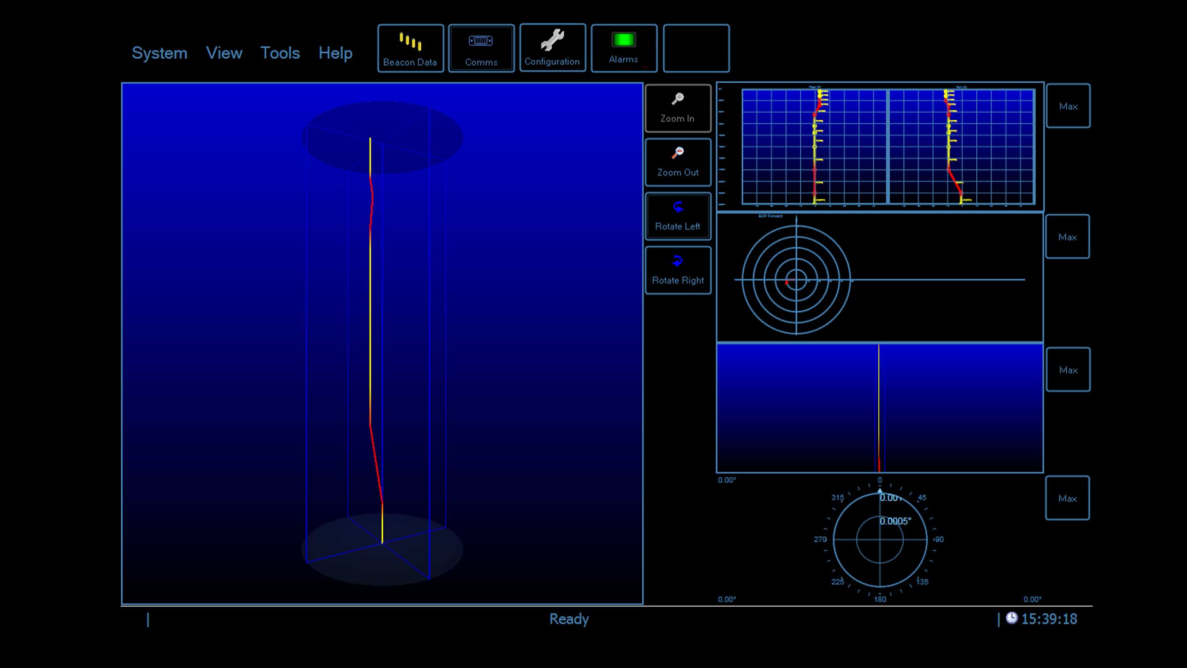
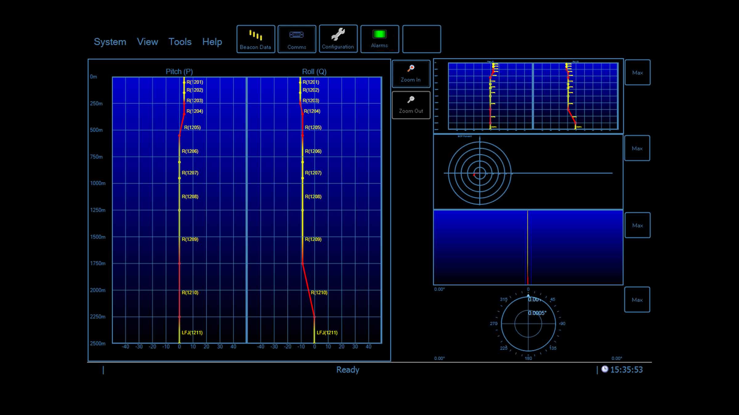
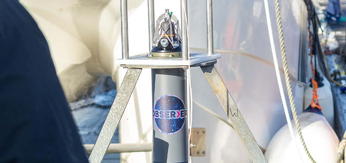
In-built sensors capture high-frequency motion for vortex induced vibration (VIV), flow-induced vibration (FIV) and structural behaviour monitoring. This combination simplifies and expands your ability to truly understand the behaviour of your infrastructure. 

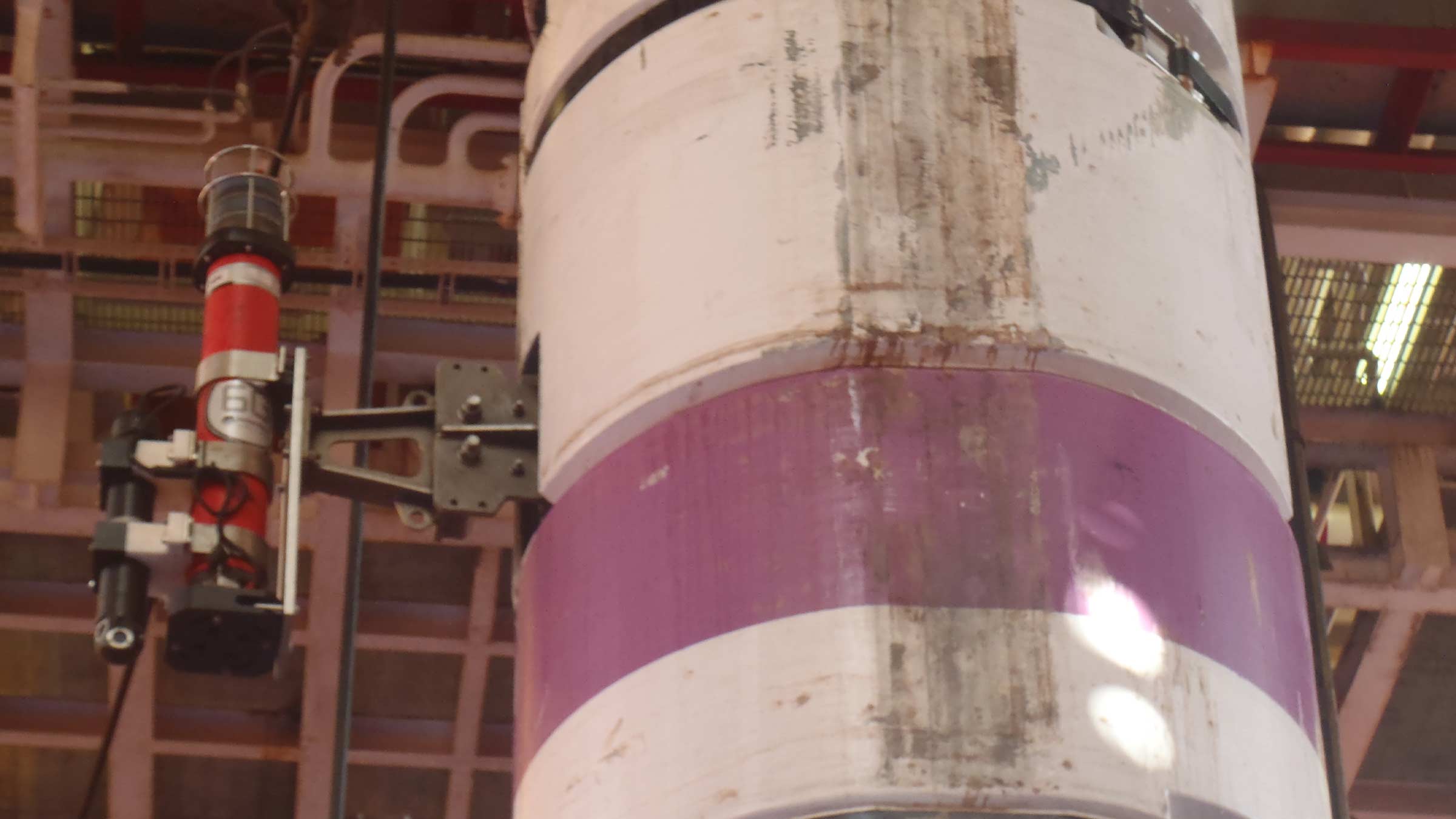
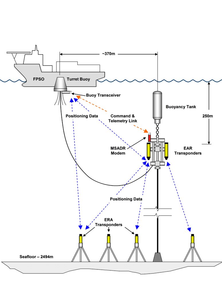
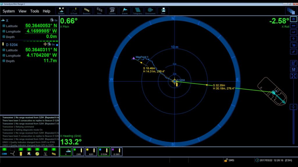
Observer can operate as a Long BaseLine (LBL) node for highly precise low-frequency motion monitoring such as pipeline creep and movementIt also supports Ultra-Short BaseLine (USBL) positioning, for measuring assets movements in the water column, like riser and umbilical movement. Also allowing data retrieval from a vessel or underwater vehicle. 

Always informed. Always in control – flexible data retrieval

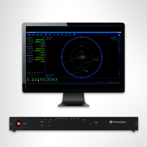
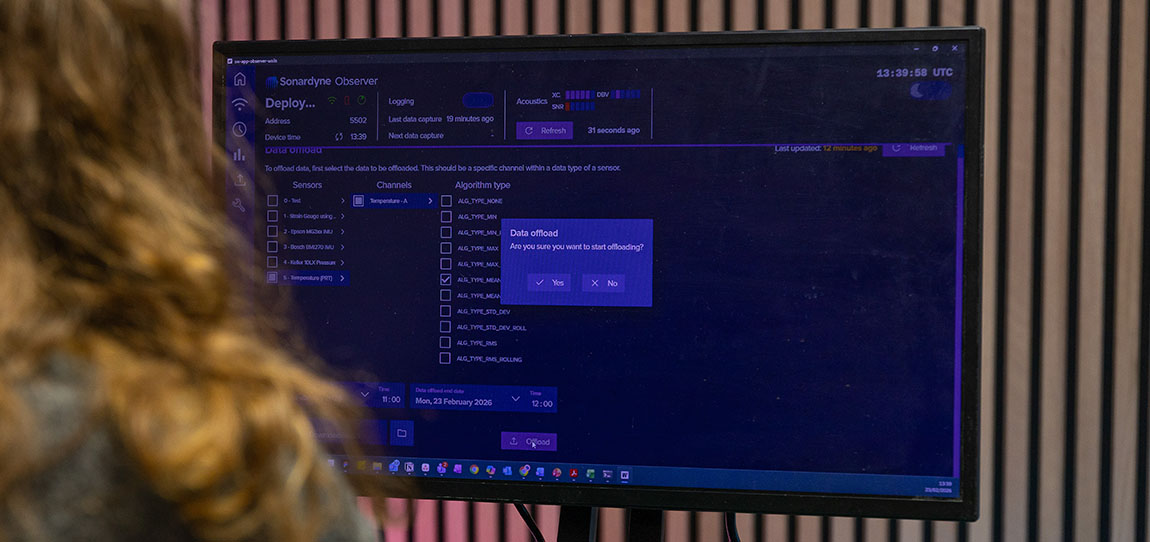
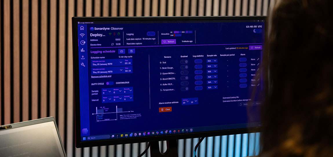
Easily setup, check your configuration and QC your sensor data pre-deployment, and also adjust it acoustically post-deployment, using our intuitive web user interface.  

Set and modify data collection and offloading schedules at any time.  

Our trusted acoustic telemetry provides your seafloor-to-surface communications, in all water depths, even in challenging acoustic environments.  

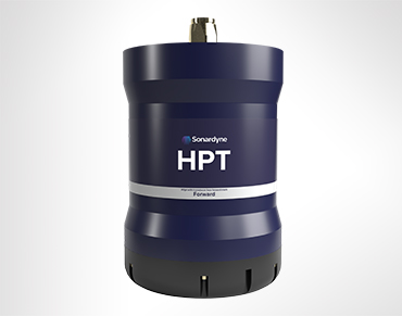
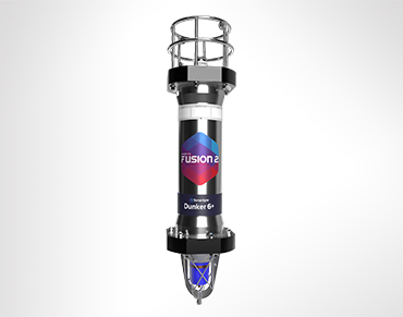
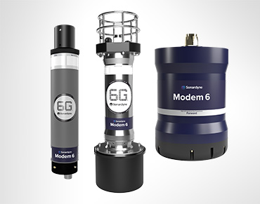
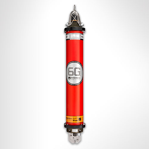
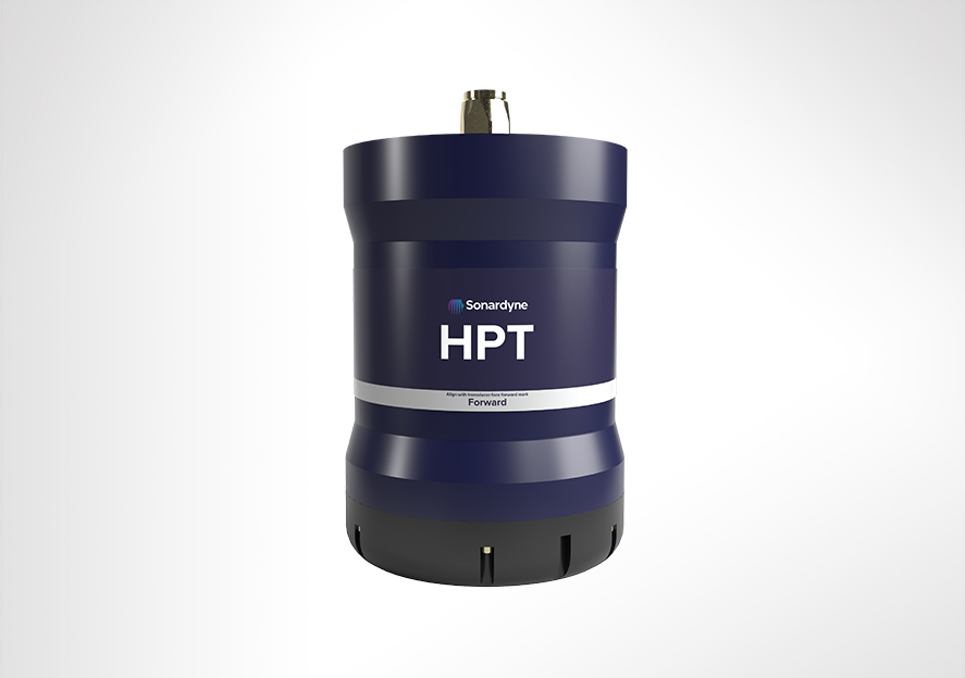
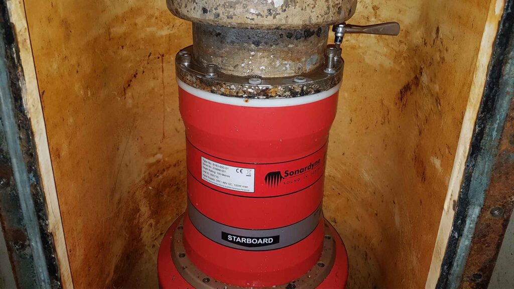
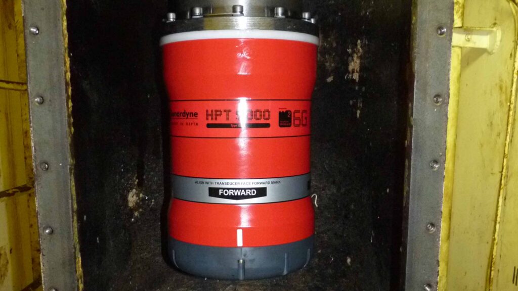
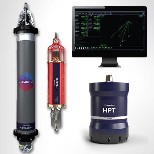
Compatibility with our 6G ecosystem enables data transfer at up to 9,000 bps to topside transceivers and modems, including our HPT 5000, Modem 6+ and Dunker 6 

An Ethernet communication link allows larger quantities of data to be harvested directly from subsea control systems or subsea vehicles. 

Observer at a glance

  • Up to 10-year endurance for fewer interventions  
  • ROVdeployable and recoverable for easy installation 
  • Rated to 3,000 m (7,000 m option) for global operations  
  • Onboard logging and analytics with acoustic offload on demand 
  • High and low-frequency motion monitoring in a single device 
  • Built on our lowpower 6G hardware and Wideband 2 digital signal architecture for trusted subsea communications 

Sensing

• 6 DOF high-performance sensor fitted as standard
• Sampling rate: 5 Hz, 10 Hz, 25 Hz
• Data storage: 64 GB, dual redundant
• Processing capability: Fully programmable including analysis, statistical functions and bespoke options

Design

• 3,000 m depth rating; up to 7,000 m on request
• ROV-friendly design; option for ROV mounted clamps
• Aluminium standard housing material; options for different materials depending on deployment duration and environmental conditions

Acoustics

• Over 500 unique addresses, ideal for large array deployments
• Data transfer rates of 100 to 9,000 bps – user selectable
• Omni-directional transducer for wide area acoustic coverage
• Sonardyne Wideband 2 MF band (19 – 34 kHz); field proven in high-noise subsea environments

Expected battery life (typical/max life/max sampling)

• Up to 10 years (duty cycle logging pressure, temp and motion)
• 4+ years for a typical riser monitoring application (duty cycle logging USBL position, motion, depth, temp and SV)
• 2.5 years continuous logging (motion, depth and temp)

Specifications Table

Features Specification (Type 620-0762)
Acoustic operating frequency MF omni acoustic modem 20-34 kHz (alternative options available on request)
Expected operating range Up to 3000 m slant range
Sampling rates Sensor dependent, configurable decimation
Data storage 64 GB dual redundant
Data processing Min, max, mean, std deviation
Internal sensors Pressure sensor – standard 30 / 300 bar 0.01% FS, additional options available on request
Temperature sensor – standard ± 0.1 °C
IMU – standard 6 degrees of freedom – gyroscope (offsets ± 20 mg) and accelerometer (offsets ± 0.5 deg/sec)
High grade IMU – optional 6 degrees of freedom triple gyroscope (± 0.1 deg/sec) and tri-axis accelerometer (offsets ± 2 mg)
Connectivity 1x 8-way external sensor connector 4-20mA interface
12V external power output
0-12V voltage input
RS232/485 interface
2x 4-way external sensor connectors mV/V (wheatstone bridge type sensor)
1x 8-way connector for power and comms 24V external power input Ethernet
Electrical Standard battery specifications 1872 Wh primary lithium non-rechargeable battery pack (alternative capacities available on request)
Expected battery life (typical/max life/max sampling) Up to 10 years (duty cycle logging pressure, temp, & motion)
4+ years for a typical riser monitoring application (duty cycle logging USBL position, motion, depth, temp & SV)
2.5 years continuous logging (motion, depth, temp)
Mechanical Construction Aluminium (super duplex / titanium on request)
Dimensions (height x diameter) 927.5 x 132 mm
Approx weight in air/water 18 kg / 10.26 kg
Environmental Depth rating 300 / 3000 m (dependent on pressure sensor)
Operational / storage temperature -5 to 55°C / -20 to 55°C

Datasheets

Watch

Monitoring slugging events and spool piece fatigue

Thousands of kilometres of pipeline, flowline, and interconnecting spool pieces are installed on the world’s sea and ocean floors. They create vast networks and their design can be complex, having to account for a huge array of variables, from water depth to expected flow composition and behaviour.

The challenge

Sometimes, it’s not always possible to account for all of the variables that an oilfield infrastructure is subject to. This can lead to issues. External vortex induced vibration (VIV) or internal flow induced vibration (FIV), which can sometimes be caused by slugging. Slugging is created by variable or irregular flow of gas and fluids through risers, pipelines, flowlines or spool pieces.

These issues can cause problems for process equipment, impact production efficiency and, critically, accelerate pipeline fatigue. This has knock-on effects for design life. It can even cause pipelines to be displaced, entrenched or erode the supports they stand on.

When FIV occurs, pipeline engineers need all the information they can get about just how much this is happening and to what degree. This enables them to re-calculate the remaining fatigue life of the infrastructure and decide on the best remediation methods. Unfortunately, monitoring exactly what is happening – what forces the pipelines, flowlines or spool pieces are being subjected to – can be challenging, especially in deep water.

International subsea engineering company Oceaneering International Inc. was asked by an operator to solve this exact problem. They had a number of spool pieces deployed in more than 1,000 metres of water, running between riser bases and flowline termination assemblies. They were being subjected to sudden and frequent slugging movements.

These movements had already resulted in new spool piece supports having to be installed. The operator’s engineers needed to assess the resilience of the new supports and learn more about the vibration the spool pieces were encountering. The challenge was that no motion monitoring sensors had been fitted prior to commissioning. The solution would need to provide accurate and accessible data using a technique that was not cost-prohibitive to install and operate.

The solution

Oceaneering’s solution used an innovative, wireless approach with Sonardyne’s Subsea Monitoring, Analysis, and Reporting Technology (SMART) sensor as a key element of the project.

SMART sensors are, well, smart. They contain low-power MEMs-based (micro-electric mechanical systems) inertial measurement units (IMUs), subsea processing power and integrated acoustic modem capabilities. This means they can autonomously measure, log and process high-frequency, pipeline or spool piece acceleration and angular rate motion over pre-programmed monitoring intervals.

Importantly, SMARTs, which can be integrated with many different subsea sensors to suit a wide variety of applications, process data at source. This is then sent as small statistical summary packets of data – based on parameters set by the user – through the water column to a surface transceiver. This method reduces the need to send time-series, or raw, data up to the surface for analysis, which prolongs battery life, maximizes bandwidth availability and provides useful information to engineers faster. It’s edge analytics and subsea communication technology in one battery-powered autonomous compact unit. And it’s able to work on extended deployments down to 7,000 metres water depth.

For the high-frequency motion, SMARTS were installed on each spool piece at a location between the riser and flowline termination assemblies. To monitor lower frequency movement on one of the spool pieces, another Sonardyne technology was used: Autonomous Monitoring Transponders(AMTs).

AMTs are most commonly used for long-term survey and monitoring tasks where instruments are needed for acquiring acoustic ranges and sensor data without surface control. They time-stamp data and log it internally, to be retrieved when it’s needed at the surface.

By creating a Long BaseLine (LBL) array of “static” AMTs, to which “mobile” AMTs installed on a spool piece and fitted with sound velocity sensors can range, highly precise measurements of any horizontal movement of that spool piece can be monitored and logged. By fitting the mobile AMTs with Digiquartz pressure transducers, vertical motion could also be tracked accurately within the array.

Before installing the SMARTs and AMTs, Oceaneering surveyed the seabed location. This was done to determine the LBL array design and SMART and mobile AMT positioning. Oceaneering designed and built ROV-installable spool monitoring clamps. This allowed the SMARTs and AMTs to be easily attached to the spool pieces. For the LBL array, four AMTs were placed in tripod stands at predefined locations for optimal ranging.

Following installation, confirmation that all the SMARTs and AMTs were working and a post-installation survey, the autonomous and intelligent instruments were then just left to do their work. A huge benefit of both instruments’ design is that they can be left unattended for three years thanks to their internally monitored lithium primary cells.

Anyone with these instruments deployed in their field has a choice in how to collect the data generated. If it’s close to a topside facility, they can deploy a Sonardyne Dunker 6 transceiver permanently, via a deployment pole for the duration of the monitoring, or temporarily over-the-side, via a winch or A-frame.

If the subsea infrastructure is more remote, they could periodically send a support vessel or an unmanned autonomous surface vessel with a Dunker 6 to harvest the data. For this project, while the site was deep, it was close enough to the customer’s production facility. Oceaneering chose temporary deployments, using the Dunker 6 from an onboard crane, as and when data collection was required.

The results

Since commissioning in the summer of 2018, continuous SMART monitoring of the spools, at four-minute intervals has taken place. Packets of data from both SMART and AMT devices, including raw runtime data, have routinely been sent to the surface. Once received, it has been analysed and used in predictive modelling. This has enabled the operator to calculate the accumulated fatigue and remaining operational design life of their assets.

Gaining access to the spools’ motion characteristics has been invaluable to the operator. It’s data they would have been expensive to access through other means. It has led to a deeper understanding of each spool’s motion frequency, rotation angles and cycle times. Where previously the operator had concerns about the remaining operational life of the spools, they now know the operational life is within the limits of the productive life of the field.

This is a great result for the operator, but also for Oceaneering and Sonardyne. By working together we were able to find a cost-effective and viable solution for the operator and future customers with similar challenges. By combining our expertise and flexible instruments as an integrated solution, the supply chain is able to tackle operators’ deepest challenges, quite literally.

Jump to

Overview

Real-time subsea asset monitoring

Providing a wireless vertical profile of current speed and direction, temperature and inclination, our Riser Profiling system (RPS) is your solution for real-time subsea asset and riser monitoring. Whether your risers are deployed from drilling or production vessels, our RPS gives you confidence in their integrity with real-time observations.

Precision depth monitoring for offshore operations

The Riser Profiling system can be used as a standalone, integrated within a Marksman LUSBL acoustic position reference system, or with a third-party integrated monitoring system.

6th Generation (6G®) DPTi or SMART transponders wirelessly mounted along the length of the riser, provide highly accurate data. These are clamped onto the riser during deployment or installed via ROV subsea. Up to ten transponders are mounted on a riser. Each transponder is fitted with the following sensors:

  • High-resolution dual axis inclinometer
  • Water temperature
  • Pressure and depth
  • Optional single point Doppler current meter (speed, direction)

The gathered data is transmitted wirelessly from the transponders using our Wideband 2 acoustic signals to a transceiver on the vessel, eliminating the need for expensive umbilical cables to fitted up each riser.

At a glance

  • Designed for monitoring your riser’s integrity
  • Helps prevent critical damage during operations
  • Removes need for expensive cables
  • 6G hardware and Wideband 2 acoustic delivers robust performance during operations
  • User configurable update rates

Advanced monitoring for subsea success

Topside software makes changing monitoring regimes easy. You can even set an alarm to activate when the calculated riser angle exceeds a predefined limit.

At the update rate you choose, inclination, current speed and direction, pressure, temperature measurements are requested from each transponder. All data is processed, logged and displayed graphically and numerically on the topside computer software for your instant analysis. When SMART transponders are used, the data is processed within the transponder and wirelessly transmitted to the vessel’s transceiver.


Specifications

Rider Profiling System Equipment Required
Topside Computer Hardware Sonardyne Navigation PC (marine approved)
Operating System Windows®10
Acoustic Sensor Interfacing and Time Sync Sonardyne Type 8098 Navigation Sensor Hub (NSH)
Vessel Transceiver Sonardyne Type 8142 HPT (LMF band)
Riser Transponders Sonardyne Type 8300 DPTi 6 (LMF band)
Sensor Accuracies Temperature (PRT) ±0.1°C
Pressure/Depth (Strain Gauge) ±0.01%
Dual Axis Inclinometer (Pitch/Roll) ±0.05° over 0 – ±15°; ±0.2° over 0 – ±45°
Current/Water Velocity
(Single Point Doppler)
1% of measured value ± 0.5 cm/s

Support

• Comprehensive and flexible training for system operators
• 24-hour support, whenever and wherever you are in the world
• Custom configured to meet your exact operational requirements
• Systems are manufactured and tested before delivery at our world-class in-house facilities

Design

• Operating depth range 3,000 m (5,000 m)
• Robust two-way communications
• Compatible with all makes of DP system

DPTi 6 at a glance

• High accuracy inclinometer range: ±90°
• Accuracy: 0° to ±15° = ±0.05°; 0° to ±45° = ±0.2°
• Temperature ±0.1°C
• Tilt switch ±30-45°
• Strain gauge pressure sensor ±0.01%
• High precision strain gauge (optional) ±0.01%

Hardware overview

• Compatt 6 DPTi riser transponder
• Riser Profiling software
• HPT Transceiver
• Marine Computer
• Ethernet Serial Hub (ESH)
• Riser mounting buckets available

Rising to the challenge: riser tower monitoring

When Petrobras's Cascade and Chinook development went into production in 2010, it claimed two major milestones. It was the first floating production, storage and offloading (FPSO) facility used to accept production from the fields in the Gulf of Mexico, at 2,600 m. It was also the world's deepest operating FPSO.

The Cascade Chinook fields lie 180 miles offshore in the ultra-deep water of the Walker Ridge block. Petrobras America Inc. (PAI), the fields’ operator, fast tracked the development with the use of a converted tanker (later sold to Murphy Oil who now operate the FPSO).  

Oil production is facilitated through free standing hybrid risers (FSHRs) connected to flowlines from the field to serve the FPSO, delivering oil and gas to the surface for processing and exporting processed gas to a subsea pipeline.  

Crude is offloaded to a shuttle tanker. All risers and umbilicals are integrated into a disconnectable submerged turret buoy that allows the FPSO to weathervane and move off-station as required.  

Life-of-field monitoring

To maintain the integrity of the FSHRs, the Subsea Technology Group from Petrobras’s R&D Centre in Brazil, prepared a specification for PAI of a comprehensive life-of-field subsea monitoring system and contracted BMT Scientific Marine Services as the systems integrator responsible for its delivery.  

BMT has experience in the development of offshore monitoring systems and, following the successful development of a similar system for the Petrobras P·52 platform in Brazil in 2007, BMT again chose to partner with Sonardyne for the positioning and telemetry component of the riser monitoring system. 

The primary requirement for the acoustic instrumentation is to monitor the position of each riser tower and of the turret buoy relative to the seabed. In addition, integrated sensors monitor depth, temperature, inclination and sound speed whilst the integrated modem transfers data from the load and attitude monitoring system on each riser tower to the turret buoy. The system uses Sonardyne Wideband acoustic telemetry to guarantee high speed and reliable data communications for all these tasks. 

Integrity – Measure, command and monitor

To ensure line-of-sight to each riser tower without obstruction by the flexible risers or mooring lines, the turret buoy was equipped with three of our transceivers. The transceivers perform the following multiple functions: 

  • Measure ranges directly from themselves to the seabed transponder array in order to provide an accurate position for the turret buoy. 
  • Send commands to transponders mounted near the top of each riser tower, instructing them to measure the ranges to the seabed array. The positions of the risers can then be accurately determined.  
  • Acquire sensor data from the riser transponders and the seabed array. 
  • Send commands to, and recover data from, BMT’s data logger on the risers, fitted with an acoustic modem.

The transponder on the risers and on the seabed are versions of our Autonomous Monitoring Transponders (AMTs) which operate an efficient Wideband command protocol. 

This allows much faster set up of transponder parameters and enables the sensors fitted to the riser transponders to be measured and reported at the same time as the acoustic measurements are made, greatly speeding up the acoustic monitoring cycle. 

In normal operation, data acquisition will be controlled by the topside monitoring system on the FPSO. In the event of a disconnection due to adverse weather or maintenance, the subsea system continues to record data on the turret buoy, which can later be downloaded by the FPSO or another vessel for processing by Petrobras proprietary software.  

The integrity monitoring system provides valuable data about the movement from either vortex-induced vibration or flow-induced vibration and loading on hybrid riser systems from currents and extreme weather events. 

The system demonstrated a growing demand for reliable subsea remote integrity monitoring that has been enabled by the high performance of Sonardyne monitoring and acoustic positioning, data communication systems and subsea strain and motion sensing systems.  

P-52 permanent subsea riser monitoring system

Sonardyne previously supplied the acoustic positioning and data recovery equipment for the single FSHR close to the Petrobras P-52 platform in the Brazilian Roncador field.  

Installed in the Autumn of 2007, a single acoustic transceiver on the platform communicates with the transponders and modem on the risers and with a seabed array of five Sonardyne Compatt 5 transponders.

Because of the large amount of data to recover from the data logger on the risers – over 90 Mbytes in the first six months – our High Data Rate Link (HDRL) was employed to transfer data from the loqqer to the platform. The monitoring system sends strain, motion and position information every four hours. 

This transfers data at the speed of 15,000 bps and is ideal for transferring the large data records to the surface error free and as efficiently as possible.  

Since its commissioning in 2007, the system has provided invaluable data for analysing the movement of the riser tower, allowing confidence in the development of more complex FSHR installations such as in the Cascade and Chinook field. 


(The original version of this article was first published in Sonardyne’s Baseline magazine in 2009. It has been lightly edited for present tense).  

https://www.sonardyne.com/wp-content/uploads/2021/06/baseline_issue_4.pdf  

Jump to

Overview

Track anything, to any range

HPT 5000/7000s are acoustic and telemetry transceivers designed for use with Ranger 2 USBL and Marksman LUSBL systems. HPT 5000 enables targets to offer wide range of water depths to be tracked. HPT 7000 is optimised for noisy DP drilling and construction vessels and in deep water. Suitable for a wide range of applications from pipeline positioning and riser monitoring to subsea structure installation as well as tracking and communications.

Overview

When it comes to USBL and LUSBL transceivers, one model does not fit all situations and vessels. For Ranger 2 and Marksman installations, our High Performance Transceiver (HPT) is available two primary configurations.

HPT 5000
HPT 5000 offers full hemispherical acoustic coverage so it’s a popular choice for tracking multiple targets  (ROVs, AUVs, towfish, seafloor sensors) over a wide range of depths and elevations. The unit is also suitable for dynamic positioning reference on survey, research and offshore support vessels.

HPT 7000
HPT 7000 is engineered for ultra-deepwater operations, tracking targets far below (rather than to the side) of a vessel, and also high vessel noise operating environments, as those typically encountered on DP drilling and construction where aeration from thrusters is liable to cause signal interference.

Both models of transceiver fully support 6G LBL operations using Fusion 2 LBL software. They are also highly capable acoustic communications modems, able to interrogate, command and recover data payloads from deployed Sonardyne instruments including AMTs and Fetch. Supporting telemetry rates of up to 9,000 bps minimises the time a vessel has to wait on location to recover data, as well as supporting LBL operations.

HPT 5000/7000s are also available in Gyro USBL configurations offering calibration-free installation and use.

At a glance

  • Use with Ranger 2 USBL and Marksman LUSBL systems
  • Can also be used to communicate and harvest data from Sonardyne sensors
  • Hemispherical (HPT 5000) or directional (HPT 7000) arrays to suit your vessel and application
  • Can be deployed other-the-side, through-tube or through-hull
  • Suitable for new-build vessels or USBL/LUBL upgrade for your existing vessel

All HPTs are built on our 6G technology platform with multi-element processing to enable transponders to be positioned more precisely, more quickly and more robustly due to improvements in signal processing algorithms and array design.

Functionality such as ‘Discovery Mode’ enables vessels equipped with Ranger 2 and Marksman to enter an offshore area and automatically detect previously deployed transponders (including their configured address and channel), making simultaneous operations using shared seabed arrays possible.

Manufactured in aluminium-bronze, HPTs are intended to be fitted temporarily or permanently to a vessel’s through-hull or over-the-side pole. HPT 5000s (including Gyro USBL 5000s) have also been fitted to large USVs for uncrewed missions controlled from over-the-horizon.

For specialist applications, inverted USBL, LMF frequency and extreme depth range HPT transceivers are also available. Please get in contact to discuss your requirements.

Specifications table

Note: The absolute accuracy of the system is dependent upon the quality of external attitude and heading sensors, beacon source
level, vessel noise, water depth, mechanical rigidity of the transceiver deployment machine, SV knowledge and proper calibration of
the total system using CASIUS.

Feature Type 8142-001 Type 8142-002 
(deepwater optimised unit)
Operational frequency MF (20–34 kHz) MF (20–34 kHz)
Transceiver
performance
Operating range Up to 7,000 m Up to 7,000 m
Acoustic coverage Up to ± 90° Up to ± 90º Optimised for deep water
(depending on frequency of operation)
Range precision Better than 15 mm Better than 15 mm
Positioning repeatability All transceivers tested to better than 0.1% of slant range 1 Drms All transceivers tested to better than 0.07% of slant range 1 Drms
Transmit source level (dB re 1 µPa @ 1 m) 200 dB 200 dB
Tone Equivalent Energy (TEE) 206 dB (13 JA) 206 dB (13 JA)
Electrical 48 V dc (±10%),
Typical 15 W, Max
120 W
48 V dc (±10%),
Typical 15 W, Max 120 W
Communication RS485, baud rate switchable,
ethernet 100 Mbps
RS485, baud rate switchable,
ethernet 100 Mbps
Operating temperature -5 to 40°C -5 to 40°C
Storage temperature -20 to 45°C -20 to 45°C
Mechanical construction Aluminium bronze Aluminium bronze
Dimensions (length x diameter) 322 x 225 mm 391 x 310 mm
Weight in air/water 26.7/15.3 kg 46.9/29.0 kg
Options Tilted array adaptor Tilted array adaptor

Did you know?

Both HPT 5000 and 7000 are available in Gyro USBL configurations