You will find out the main differences between each of these pieces of kit and which one will suit your requirements.
The ROVNav 6+ and Mini ROVNav 6+ share many of the same capabilities and technology. Both can be used for both ranging and telemetry. However, the most notable difference between them is the size and weight. The Mini ROVNav 6+ is less than half the diameter of the ROVNav 6+ main housing and two thirds of the length, as well as the total system weight being less than a quarter of the ROVNav 6+, meaning that it can be used on much smaller platforms and autonomous vehicles.
In comparison the larger ROVNav 6+ has additional features such as a remote transceiver, can transmit at greater range of frequencies over longer ranges or in noisy environments, has higher accuracy sensors than the Mini ROVNav 6+, and can also be fitted with additional sensors such as a high precision strain gauge.
| ROVNav 6+ | Min ROVNav 6+ | ||
| Depth Rating | 3000m/5000m/7000m | 3000m | |
| Dimensions (L x D) | 768mm x 200mm | 504mm x 93mm | |
| Weight in Air/Water | Housing | 15.5/6kg | 5.1/2.2 kg |
| Transducer | 3.3/2.8kg | ||
| Cable | 2.7/1.4kg | ||
| Transmit source level | 187-196 dB | 181-187 dB | |
| Range precision | Better than 15mm | Better than 15mm | |
| Battery life (listening) | 3 Days | >7 Days | |
| Operating voltage | 24 or 48 V dc (+/-10%) | 24 or 48 V dc (+/-10%) | |
| Serial comms connector | Subcomm 8 way (female) | MCBH8M | |
For more information about these products and for help deciding which is more suitable for your needs, please contact your local Sonardyne office.
Why do you need to QC Sound Velocity in Fusion 2?
Sound velocity (SV) is a critical part of acoustics that is used with the travel time between instruments in order to calculate a range. This means that any error in your sound velocity will be included in the range and therefore the position may be incorrect.
In order to ensure that your positioning is optimal then it is important to check your sound velocity used in your Fusion 2 system is correct.
- Check your data is coming into the system, at the correct rate and it has been selected in Environmental Configuration window. The data is visible in the measurements window, the instrument comms and in the environmental configuration menu.
- Compare your SV with another SV sensor i.e. if you have a Compatt with an SV sensor. The SV values should be very similar.
- If you have two calibrated Compatts. You can obtain a baseline derived sound velocity. In Fusion 2 you can find this in the Environmental Configuration window > Sound velocity

Remember that Sound Velocity changes rapidly across locations and depths. When comparing SV’s try to compare these from the same location at the same time.
When Compatt 6+ transponders are deployed, they can be installed at varied heights off the seabed depending on the method of deployment (stands, floats, etc).
Stands offer greater stability but are restricted to typically 2-3m height off seabed, whereas floats allow the Compatts to be deployed much higher off the seabed.
There are several reasons why you would install Compatts higher off the seabed, these include:
- Improved visibility between Compatts
- Avoid undulating topography
- Increased maximum range between Compatts
We use specialist software, RayTrace, and sound velocity profiles from worksites to determine the optimum Compatt height off seabed. Sound waves move towards lower velocity areas so ray paths bend in the water column. RayTrace allows an estimation of the maximum achievable baseline range and presents this in graphical form. See below the images from RayTrace software which shows how height above the seabed affects the maximum Compatt to Compatt range. The first image demonstrates Compatts 2m off seabed with a 1200m maximum separation, compared to the second image where the Compatts are 5m off the seabed and can achieve over 1800m maximum separation.


However, using floats means that there will be slight movement (deflection) of the Compatts due to ocean currents. Sonardyne performed an analysis of deflection of low drag and square sided floats to determine the amount of movement at different length strops (height above seabed). The full results of this study can from [email protected].

In this video we’ll show you how to replace the battery in our Compatt 6 and 6+ family of transponders. This is the same process for replacing the battery in the following transponders:
Before you get started you will need a long M4 bolt, a pair of long nose pliers, 8mm nut driver or a set of hex keys, yellow Compatt opening tools and the replacement battery.
Ensure that you are in a well ventilated area and if the battery has leaked or there is any sign of water ingress, make sure you wear the correct PPE such as gloves and goggles.
Autonomous Monitoring Transponder (AMT)
Dynamic Positioning Transponder (DPT)
Pressure Inverted Echo Sounder (PIES)
This article aims to help planners avoid the standard pitfalls of planning a Sparse LBL array.
Planning an array ahead of time
It is best practice to plan a transponder array deployment before it is placed on the seabed. This can be for a number of reasons and can highlight potential issues before the job has started:
- Avoid areas such as overage curves anchor scour locations areas deployment corridors etc
- An array plan will include an SV analysis that will define the expected range of your Compatt transponders at different depths. This will avoid a situation where a Compatt that you need, maybe is out of range
- The seabed is not always flat, strategically placing Compatts at the top of mounds for example, can lead to less Compatts being needed so less vessel time is needed and money is saved.
- Do you need specialist software to do an array plan, arguably yes. Though Sonardyne does offer an inhouse array planning service and will soon offer a cloud-based planning portal for all those who want to create their own arrays.
In order to perform an array calibration, you will need:
- A Sound velocity profile (SVP) taken at the location in question (preferably at the same time of the year) and covering all depths at that location (SV smoothing / QC may be necessary depending on the quality of your SVP)
- A .xyz Digital Terrain Model (DTM) of the area in question preferably under a Gb in size .
- A .dxf drawing that covers all relevant subsea infrastructure. Preferably one that does not have every nut and bolt included as the smaller the drawing the more efficiently the system will run.
- A list of x y coordinates for the Compatt along with transducer heights (usually depending if you are using stands / floats or a combination of) (Z is usually defined by the system as it plots the x y and adds the transducer heights).
Once you have everything it is worth working out the distance that you want to cover and defining the type of array that you are going to be using:
- Standard LBL,
- This will require two box-ins or two known coordinates, at least one SV Compatt and a standard ROV setup
- No INS needed.
- 2D SLAM calibrated LBL,
- This will require two box-ins or two known coordinates at the beginning and end of a predefined route and no more than 6 Compatts between box-ins
- Or if working in an array you could conceivably calibrate the array relative to one Compatt/boxin
- INS needed.
- 3D SLAM calibrated LBL
- This will at least one box-in or a known coordinate.
- INS needed.
Contact [email protected] for more information.
What are the steps for a sparse LBL Calibration in Fusion 2
Option 1 2D
Step-by-step guide – How-to
Establish USBL drop coordinates for the array in planning and confirm when deployed (assign semi major / semi minor errors to the drop coordinates the default is 10m but this can be changed depending on the spread observed when doing the box-ins).
Compatts should be placed so that a decent angle of cut can be achieved to the location that you want positioning in 60° being the minimum.
Box in the first and last Compatt if working along a route.
Currently the system can handle three Compatts in the SLAM algorithm at one time so plan accordingly. Starting with a box-in Compatt moving past that and along three uncalibrated Compatts and then finishing that SLAM before starting a new SLAM. Then moving three Compatts along and then finishing by moving past a boxed-in Compatt.
For best results start in an LBL array or on a known location. When I say on a known location, I don’t mean close to I mean cm from or perfectly on any error in the initial start point can translate into future error in Compatt position, depending on the scale of the error.
2D array calibrations do not need a DQ loops but they need a definition of depth from the ROV on deployment this can be achieved by placing the bumper bar up against the Transducer on deployment and then reducing this for tide once all Compatts have been deployed.
High accuracy measurements are not needed as all 2D array Compatts should be a minimum of 150m away from the route that is to be surveyed. This range minimises the effects of any depth error that might be present.
Option 2 3D
Step-by-step guide – How-to
Establish USBL drop coordinates for the array in planning and confirm when deployed (assign semi major / semi minor errors to the drop coordinates the default is 10m but this can be changed depending on the spread observed when doing the box-ins).
Compatts should be placed so that a decent angle of cut can be achieved to the location that you want positioning in 60° being the minimum.
Box-in your reference Compatts or at least establish a Compatt on a known location.
Make sure that you have decent geometry from your planned circular trajectory to your boxed-in Compatt / reference Compatt.
On this note it is important to stress that if your reference Compatt is on an operation structure you may have to contend with background noise and (if the Compatt in question is low down) Line of sight issues. So be aware.
When performing your circular SLAM / trajectory with good geometry to the reference Compatt make sure that the ROV is aware of the dangers of catching the Compatt in the tether and accidentally moving it.
Please see the you tube link below for a better understanding: https://www.youtube.com/watch?v=kc99iiuk0io
For more information there is a guidance note that can be downloaded link to SLAM Guidance note
Points to remember 2D
- 10m semi major /semi minor is a guide not a standard, redefine this depending on box-in spread. Depth definition from ROV on deployment reduced by tidal curve later, no DQ survey needed.
- Start with a good definition of ROV location where possible.
- 150m from the route to be surveyed.
- Can be performed during other ops such as pre lay etc.
- Can be post processed in Janus to improve things.
Points to remember 3D
Depth definition from ROV on deployment reduced by tidal curve later, no DQ survey needed as 3D SLAM also SLAM calibrated the depth as well as the X and Y relative to its position.
Good geometry needed during calibration.
Contact [email protected] for more information.
What are the steps to set up structure deflection monitoring (SDM) in Fusion 2?
Installing large structures can be stressful for both the operator and the asset being installed. The completely wireless Fusion 2 structure deflection monitoring module uses high accuracy pressure sensors to give clear and up to date feedback on the stress and warping experienced by the asset during installation and settling.
The GyroCompatt 6+ is used to acoustically retrieve heading of the structure during landing.
It is easy to set up and get running, just follow the steps in this video:
How Fusion 2 manages different geodetic frames
Previous versions of Sonardyne LBL software positioned everything on a flat grid, based at the surface. With the increasing use of real-world systems like SPRINT-Nav, and positioning accuracy improvements with the advent of Wideband technologies, along with increasing array sizes, it became necessary to account for the difference in distances seen at the surface and at depth, due to the curvature of the earth. To do this, an elevation scale factor was computed and added to the projection scale factor to create a combined scale factor in Fusion 1. This was applied to the baselines during calibration, and the ranges during tracking, to allow them to fit the real-world positions.


Positioning on a flat surface versus positioning on a spheroid
Fusion 2 has been designed to position directly on to a spheroid, as far as the user can see. Fusion 2 does not apply a scale factor to the ranges, it uses the current geodetic settings to convert the array locations into a local unscaled frame and uses this frame to perform the calculations. It then converts the results back to the configured projection to be displayed and outputted as required. This negates the need for the user to manually calculate and apply a scale factor.
Contact [email protected] for more information.
What is Multiuser and how do I set it up in Fusion 2?
How Does Multiuser work?
Multi-user functionality allows a Compatt to be configured to listen for up to 5 different Common Interrogation Signals at the same time. This allows the Compatt to be used by 5 independent users simultaneously. They could be a mix of LBL, USBL and INS users.
Multiuser functionality is enabled by default in Fusion 2 and all Compatt 6+ devices. Compatt 6+ Multiuser has its own unique range of interrogation and reply channels that can be used in Wideband 2, 2+, 3 & 3+ modes.
How do I Configure Multiuser in Fusion 2?
Given that several independent operators may be using the array, careful user management is required to ensure there are no conflicts. As such, the connection to be used by each vessel or operator should be provided by the Project or Lead Surveyor for the project.
To change the connection being used:
- Select Tools and then select Options.
- Select the Multiuser connection and click Apply. Or click Advanced Setup to manually configure the Compatts.
- Note: When changing the connection used, this could potentially conflict with other users, so ensure that all Multiuser changes are coordinated with all users.
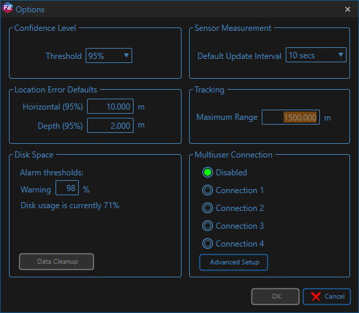
Options/Multiuser Selector
The Beacon Table will now only show the navigation settings for your connection. These can be edited as usual and this will not affect other users, other than a short delay in tracking during telemetry. Users should perform a Get All to each Compatt when first connecting to synchronise settings. Wideband 3+ NAV channels are available, if the Compatt acoustic address is set in that range.
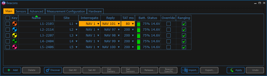
Beacon Table when set to Connection 1
How do I set ALL the Multiuser connection Settings?
This allows master control of all the Multiuser connections and would normally be used at the beginning of operations to configure the entire array, ready for incoming vessels. Settings for individual connections can also be changed using the beacon table, for normal operations.
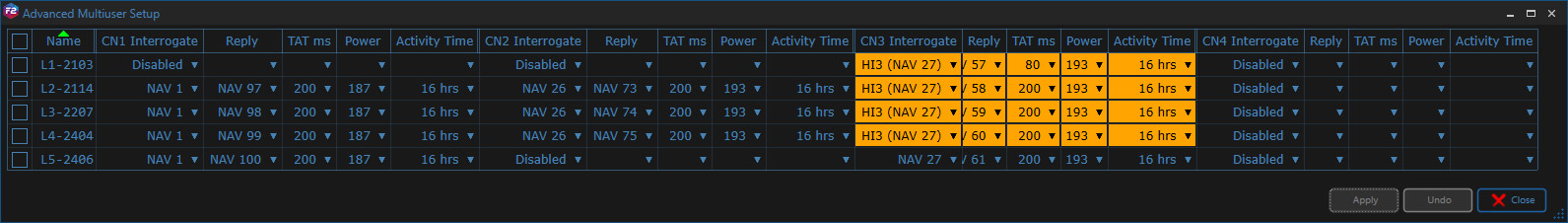
Array Properties General Tab
The user can change the Interrogation Signal, Reply Signal, Turn-Around Time (TAT), Transmit Power and Activity Time to be selected for each connection. To make the changes, use the drop-down menus, and click apply. This will begin acoustic configuration of the Compatts.
Uncommitted changes in the transponders list are highlighted in orange. Selecting a low or a high signal will automatically set the reply to an available signal in that grouping.
When choosing an Interrogation Signal the user is given two default choices, one Low (LO) and one High (HI) channel, or the user can select to Disable or manually select a channel, with Advanced…
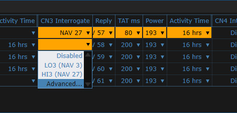
Signal selection options
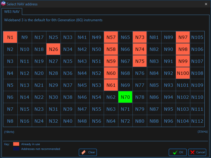
Advance signal selection
Channels already set in your system will show as pink, the newly selected channels will be shown in green.
Although it is recommended that the initial Multiuser connection configuration is organised by the Project or Lead Surveyor, there is no restriction on who can subsequently alter or manipulate these settings. As such, it is reliant on individual users to exercise discipline in working to their designated signals, and in maintaining good communication between all other users, if changes need to be made.
Contact [email protected] for more information.
What is SLAM Calibration in Fusion 2?
SLAM stands for Simultaneous Localisation And Mapping and is a process of positioning yourself in what is initially, an unknown environment, or in our case positioning a Compatt transponder in an unknown environment.
SLAM in Fusion 2, uses a SPRINT-Nav to record the ROV position changes, and acoustic ranges from a ROVNav 6+ transceiver are used to locate the Compatt as the ROV moves around the environment.
Clear and concise diagnostic information displayed during the data collection, along with real-time processing, show you when you have enough confidence in your position to meet specification.
The SPRINT-Nav can be aided using a variety of sources, depending on the task at hand, these include LBL & USBL.
For a run through of the Fusion 2 SLAM setup and collection process, please watch this video.
Contact [email protected] for more information.