The RT6 range is designed to span from coastal to deep ocean and light work to heavy work. With releases the Working Load Limit (WLL) is always a key piece of information, alongside proof load, breaking load and the maximum safe release load. But what are these for our RT6 range?
The below table summarises the limits across our entire RT6 range.
| RT 6-1000 | RT 6-3000 | RT 6-6000 | RT 6-HD | Heavy duty acoustic release frame (RT 6-3000 & RT 6-6000) Type 7869 | Heavy duty acoustic release frame (RT 6-3000 & RT 6-6000) Type 7988 | |
| Working Load Limit (4:1) | 150 kg | 1,275 kg | 1,275 kg | 2.500 kg | 7,500 kg (7.5 tonnes) | 25 tonnes |
| Proof Load | 300 kg | 2,550 kg | 2,550 kg | 5,000 kg | 15 tonnes | 50 tonnes |
| Breaking Load | 600 kg | 5,100 kg | 5,100 kg | 10,000 kg | 30 tonnes | 100 tonnes |
| Maximum safe release load | 150 kg | 1,700 kg | 1,700 kg | 11 tonnes | 11 tonnes |
Note that the individual datasheets go into more detail on the above numbers.
Any questions about WLL across our RT6 range? Contact our support and sales teams or have a look at our in-depth data sheets. If you need to go deeper or heavier let us know!
ORT and DORT? No, not Lord of The Rings characters, rather Oceanographic Release Transponders and their siblings Deep Oceanographic Release Transponders. ORT and DORT were the mainstay of Sonardyne’s deep water release offering for many years, but what have they been upgraded to?
ORT and DORT have been replaced by the below members of the RT6 family.
RT 6-3000 and RT 6-6000 have been designed as like for like replacements of the ORT and DORT respectively but with improved battery life and endurance, plus they have comparable working limit loads and you can operate them from our iWand release kit or from any Ranger 2 software.
Do you want to know more about our RT6 family, our Head of Science Geraint West introduces them on YouTube:
ORT/DORT RT 6-3000


So, you have an acoustic release which you can use to recover, monitor inclination, and localise your seabed assets. But how do you localise this position and why do you want to?
Seabed data is massively more valuable when it’s geo referenced, the dual functionality of acoustic release, acoustic transponder and inclinometer are key functions of the RT6 family.
Here we are going to focus on two ways of localising our acoustic releases:
- Using the RT 6-1000 app
- Using Ranger 2
Using the RT 6-1000 app
The RT 6-1000 app is designed to run on android smart phones and has some neat features for localising your seabed assets when attached to an RT 6-1000.
It is possible to derive an approximate location of the deployed RT 6-1000 using the “Locate” function in the RT6 App.
When the Locate process is started and the Topside Control is transmitting, the RT6 App stores the GPS position of the Android device. When the ranges are uploaded the RT6 App uses the timestamp of the ranges to link them with the Android device location at the time of the ranges. This information is stored to the database and a circle is plotted on the MAP page with a radius matching this range.
By either repeating this process or by moving vessel location during the ranging process ( a circle around the approximate location of the transponder of radius >1.5 water depth is optimal if possible), a series of overlapping circles will show on the map will give a clear indication of the deployed transponder’s location.
Below we will go step by step through the steps to use the app.
- Secure a suitable rope to the release endcap shackles ready for dunking.
- Open the RT6 App.
- Tap Locate.

- The Device Status displays the UID, Address and Firmware of the Topside Control RT 6-1000.
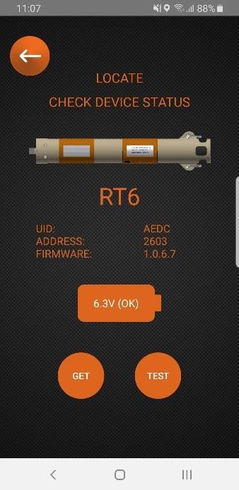
- Tap Get to refresh the information.
- Tap Next and then tap Select Address (select the address of the subsea RT 6-1000).

- Tap Locate (the Topside Control RT 6-1000 will begin transmitting every five seconds and a message confirmation will confirm if the command has been successful).

- The Topside Control RT 6-1000 is now ready to be dunked over the side to allow the range to the RT 6-1000 to be measured. Typically this involves sailing in a circular pattern in the area where the RT 6-1000 is believed to be deployed.
- The Locate status is visually displayed by the blue LED on the end cap as follows:
- Locating (collecting ranges): LED flashes every five seconds.
- After two successful telemetry commands have completed: LED changes to solid (the Topside Control RT 6-1000 will continue to collect ranges)
- When enough ranges have been collected, hold the NFC Android device against the Topside Control RT 6-1000 to automatically retrieve the ranges back to the NFC Android device; if this upload fails, tap STOP AND GET RANGES to upload the ranges again.
- The app will display an estimated position for your RT 6-1000 and you can add a waypoint at this location:

Using Ranger 2
All RT6 releases are supported in Ranger 2 with our shallow water releases also available in Micro-Ranger 2.
Did you know you can also release LMF releases with an MF USBL system? There’s an article in this knowledge base on that.
Simple waypoints and localisation
When using Ranger 2 it’s incredibly simple to add a waypoint by simply clicking the waypoint button in the software.
You can then drop a waypoint on your tracked location which will show on your navigation screen in Ranger 2, you can name this waypoint whatever you like and you can even export this waypoint to a text file.
Need more accuracy?
If you have a Ranger 2 USBL system, why not take full advantage of the accuracy? The average fix tool in Ranger 2 allows you to locate and average the position of your release transponder across multiple cycles, and it gives you a report you could deliver to a client!
Follow the steps below to do this:
- Begin tracking your RT6
- Select the RT6 of interest from the beacon list
- Click start to begin logging data, click stop to stop logging data.

- Review the statistical data for each beacon, you can even reject outliers.

- Click add waypoint to drop a waypoint on the averaged position.
- You can also export to a CSV file or a PDF report which can be delivered to a client as proof of an accurate deployment!

Contact [email protected] for more information.
First consider your error budget; how precise does your position information need to be for this job? For example, Metrology requires millimetric precision so rigid stands are your only option. But this requires planning in order to ensure stand heights are suitable to provide good line of sight between transponders, and will most likely require ROV resources to deploy and recover them. If however, you have more flexibility in your tracking solution, you may decide to go with the simpler float collar option. Deployed by freefall or ROV, tethered releasable weights keep the Compatt on the seabed as it floats upright. But be aware of currents; they’ll cause the Compatt to sway – the amount depends on the length of tether and design of float. In uneven topography, longer tethers may be needed to ensure line of sight. Our teardrop float is worth considering as it reduces drag, and minimises deflection. Our SSG team are here to help. Email them at: [email protected]
Here are some things to consider when planning a long layback towfish USBL tracking job.
If extreme range is required, our LMF (Low Medium Frequency) HPT transceiver system reduces absorption and therefore may be better suited to the task. However performance will depend on the noise signature of your vessel so make sure you have a good understanding of this.
Next, choose a transponder with a high acoustic output such as a directional 5,000 or 7,000 m rated WMT. If space on your vehicle allows, use a Compatt 6 as it has twice the acoustic power. In either case, always use Wide Band 2+ signals to get double the energy into the water.
Angle your beacon to point towards your vessel and set it to Responder mode for the fastest possible position update rates. Tilting the transceiver can open the face to vessel noise and reduce effective range so if your vessel is noisy, inverted USBL (iUSBL) could be the answer.
Contact [email protected] for more information.
Yes. To keep your Dunker 6+ performing as it should, you should clean, inspect and lubricate the bulkhead connector. This is what the manufacturer recommends:
AGP Connector mating surfaces should be cleaned to remove contamination and silicone build up then inspected and re-lubricated. This should be performed prior to each mating and before storage to insure correct mating as well as prolonged connector life. Connectors must also be mated and unmated correctly to ensure a proper seal and to prevent connector damage or degradation.
- 1. Clean the connector using the manufacturer’s recommended “3M Silicone Spray, ECG RX2200 or Dow Corning DC200” only.
- Apply lubricant and carefully and thoroughly clean the connector, locking ring and locking ring threads using a non-abrasive towel (it is not recommended to insert anything into pin or socket cavities).
- After cleaning, thoroughly inspect the connector and locking ring and look for:
– Cuts or abrasion to sealing surfaces (face of connector, overmold and pin cavities).
– Bent or broken pins and sockets.
– Deformation of the shoulder (the back of the metal locking ring presses against this shoulder to ensure connector faces mate tightly together).
– Damaged threads, rust or corrosion on locking rings. - Lubricate the connector surfaces using 3M Silicone Spray, ECG RX2200 or Dow Corning DC200.
- Apply a light machine oil or dielectric anti-seize to lubricate only the threaded portion of the stainless steel locking rings.
- Mating of locking rings should be done by hand only (do not use a wrench or pliers to tighten locking rings).
- Ensure this is no gap between the two face seals before thoroughly hand tightening the locking rings (by hand (the locking rings can be pulled back from the connector to allow a better view).
- Do not bend or twist connectors while mating or un-mating as this will damage the connector pins and sockets. Pull or push straight across the connectors. Anchor cable with foot and pull straight up if possible.
Note: do not use Contact Cleaner, WD40, CRC, DC111 or any other solvents or heavy silicone grease to clean or lubricate AGP connectors. Doing so may cause connector damage, improper mating/sealing and shortened connector life.
More information can be found in Product Catalogs on the manufacturers website.
If set incorrectly, your DPT 6 release mechanism can become damaged; it might fail to open or sinker weights may fail prematurely when lifted off the back deck. Use the following method to ensure the release is set correctly and safely.
There is a hole in the lever arm of the release and another in the side plate. Insert a 4 mm Allen key into the lever arm hole. Make sure the supplied stainless steel shackle is situated and push the Allen key towards the body of the DPT 6 to move the lever arm into place. We only use the best quality shackles; cheaper alternatives are available, but using these can put your equipment at risk.
Keeping pressure on the Allen key, insert a screwdriver in the side plate hole, across the top of the lever arm and out of the other side plate. You can now relax and remove the Allen key as the screwdriver will keep the lever arm in place.
Using 6G Terminal Lite software or an iWand, ‘Arm’ and then ‘Close’ the release. The motorised cam will close, locking the lever arm in place.
Once this is complete, remove the screwdriver, attach the weights to the shackle and your release is set.
Contact [email protected] for more information.
| Cable Function | Cable Type | Connections | Part No |
| Power & Communications | 5 metre cable with straight connector to cable tail | Lodestar CP+E1 to ROV MUX, junction box, etc.. | 317-3250 |
| 5 metre cable with right-angled connector to cable tail | Lodestar CP+E1 to ROV MUX, junction box, etc. | 317-3295 | |
| I/O (triggers, input/output position telegrams, etc.) |
5 metre cable with straight connector to cable tail | Lodestar C1/T1/T2 to ROV MUX, junction box, etc. | 317-3265 |
| 5 metre cable with right-angled connector to cable tail | Lodestar C1/T1/T2 to ROV MUX, junction box, etc. | 317-3277 | |
| Syrinx DVL | 0.8 metre straight connector to connector | SPRINT to Syrinx DVL | 820-0502 |
An optional co-locating plate (part number 650-0156) allows a DVL and Lodestar to be mated and pre-calibrated prior to mobilising offshore. If needed, the same calibrated DVL and Lodestar can be uncoupled, used independently and then re-connected and still be considered calibrated such is the precision of the Sonardyne co-locating arrangement.
Third generation Lodestar and SPRINTs (300 and 500 models), come with a standard feature called Power Pass Through.
Quite simply this means these instruments can provide power to subsea sensors that are directly connected to any of its communications ports, such as a DVL, pressure sensor or LBL transceiver. This simplifies subsea cable management and reduces the risk of wiring problems. Just make sure you’re running SPRINT V1.4 software or above. Email: [email protected] to update the software.