Sonardyne
Support Centre

The hardest part of offshore CCS isn’t injecting CO₂—it’s proving it will stay put.

In the United States, offshore carbon capture, and storage (CCS) is moving rapidly from policy ambition to permitted reality.

A major US federal incentive, 45 Q, has been introduced, in part, to enhance CCS deployment, offering up to $85/tonne of carbon dioxide for geologic sequestration.

With these incentives, project economics are improving and offshore storage advancing through regulatory review, shifting the debate beyond whether CCS should happen.

The real question now facing operators and regulators alike is how containment is demonstrated—with confidence, transparency and long‑term accountability. That question is answered through monitoring.

Why monitoring underpins offshore confidence

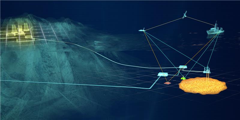
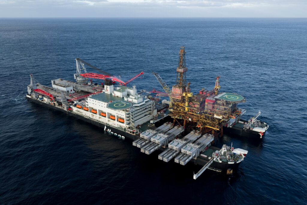
Offshore CO₂ storage offers immense geological capacity and the opportunity to reuse existing offshore infrastructure as part of a long-term emissions reduction strategy.

For the US offshore industry, CCS provides a promising growth opportunity and a way to reuse Gulf of Mexico expertise, infrastructure and subsurface know-how. But geological storage capacity alone does not build trust.

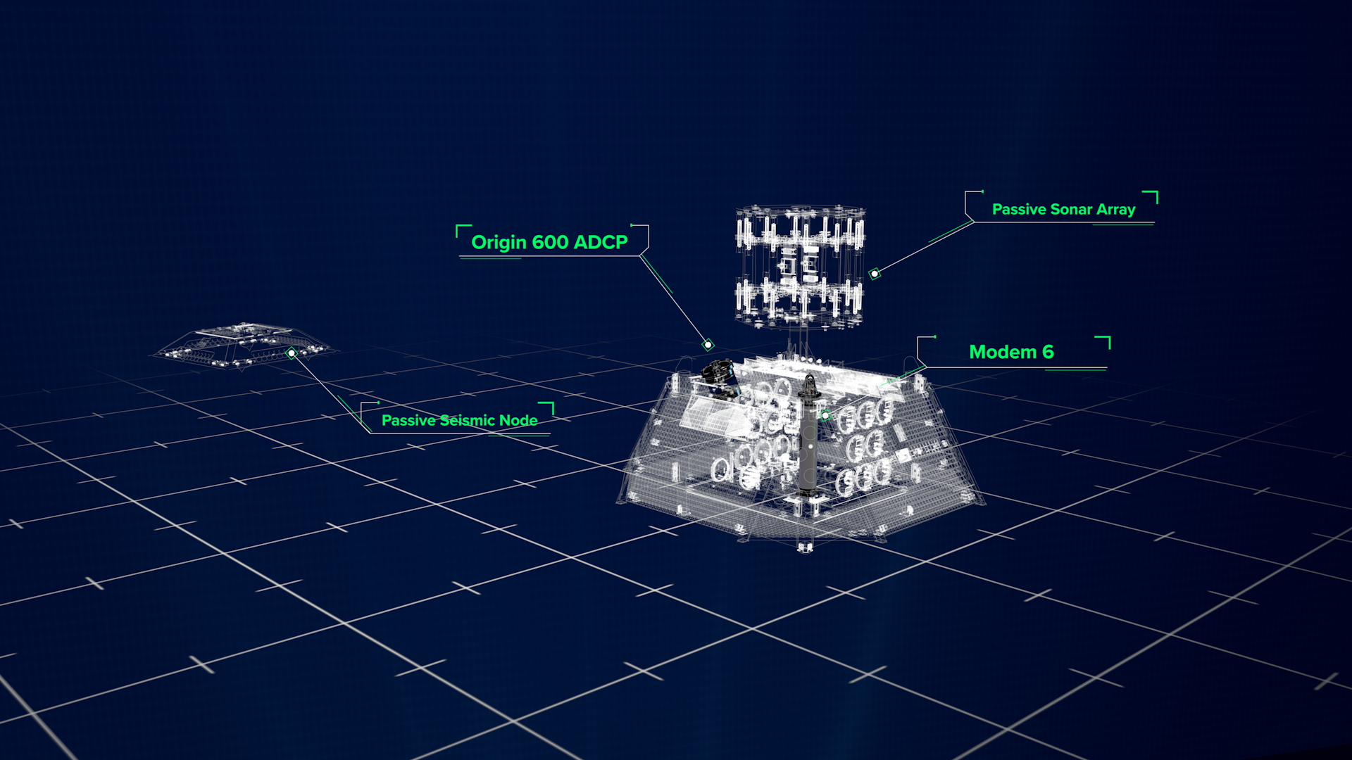
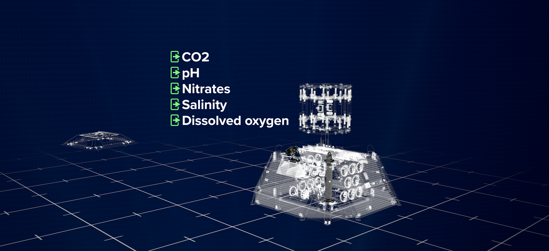
Operators, regulators and the public share a single expectation: injected CO₂ must remain safely contained for decades. Measurement, monitoring and verification (MMV) provides the evidence needed to confirm that expectation is being met and that storage behaves as modeled.

Why offshore CCS demands a different approach

Offshore environments introduce challenges that fundamentally change how monitoring must be designed. Direct, accessible methods used onshore simply don’t apply.

Unlike methane, CO₂ dissolves rapidly in seawater. Combined with tides, currents and biological activity, the offshore system is highly dynamic. These conditions make isolated sensors or single‑method solutions insufficient.

Effective offshore CCS monitoring relies on integrated, multi‑parameter strategies that observe the system holistically—above and below the seabed.

How integrated monitoring reduces risk

Modern offshore MMV programs combine complementary technologies, each addressing a critical layer of assurance:

  • 4D seismic and gravimetry to image and track CO₂ movement deep below the seabed
  • Passive seismic monitoring to constrain reservoir behavior and detect microseismic events
  • Seabed chemistry, acoustics and autonomous systems to identify early indicators above the storage complex

Together, these tools transform uncertainty into actionable insight, shifting monitoring from reactive detection to proactive risk management.

NEP: real-world validation of integrated monitoring

The UK’s Northern Endurance Partnership (NEP) carbon dioxide transportation and storage project shows how this layered approach is being applied.

The project will deploy seabed landers and ocean-bottom seismometers, to establish an environmental and seismicity pre-injection baseline to allow future comparison with data collected during the operational injection phase. Deployed near legacy wells, this process will support continuous, multiparameter observation above and below the seafloor at the Endurance CO₂ store.

By integrating geophysical methods, passive seismic arrays, and continuous seabed chemistry monitoring, NEP aims to deliver regulatory compliance and provide stakeholders with increased confidence in containment.

Sonardyne’s contribution draws on decades of subsea experience and prior CCS monitoring work, helping to operationalize an integrated MMV approach in a complex offshore setting.

MMV: more than a regulatory requirement

For offshore CO₂ store operators in the US, robust MMV is more than a regulatory requirement. Well designed monitoring programs can:

  • Support faster, more confident permitting
  • De‑risk long‑term storage liabilities
  • Protect asset value over the project lifecycle
  • Strengthen transparency with regulators and stakeholders

In a sector where scrutiny is increasing, monitoring is a strategic differentiator—not a checkbox.

Join the conversation at OTC

At this year’s Offshore Technology Conference (OTC), I will share lessons from large‑scale offshore CCS monitoring programs, highlighting how autonomous systems, permanent sensing, and risk‑based strategies are reshaping environmental assurance.

Technical session: Offshore Resilience Across Ice, Fire, and Intelligent Risk. 1400-1630, Room 604. OTC Paper: OTC‑37056‑MS

Offshore CCUS won’t scale on promises alone. What will regulators accept as proof that CO₂ stays put—now and in 30 years from now?

Wolfgang Ruf

Watch

The evolution of technology is often driven by a simple but powerful idea: there must be an easier way. Twenty years ago, our Ranger Ultra-Short BaseLine (USBL) positioning system was developed to do just that.

Designed to make high-performance acoustic positioning easier to use, Ranger has become the trusted reference across science, offshore energy, defence and autonomous operations worldwide.

A history of positioning at Sonardyne

Since its very beginnings in the 1970s, Sonardyne has been the leader in underwater positioning technology. Driven by the exacting demands of the offshore industry, we set a global industry standard for Long BaseLine (LBL) technology for subsea construction and survey.

By the 1990s, we had also introduced an Ultra-Short Baseline (USBL) system widely regarded as the industry benchmark for survey-grade performance. It could handle complex tasks such as deep-water metrology, construction support, the positioning of underwater vehicles and structures and, in L/USBL mode, a DP reference for deep water drilling units.

It was our first Windows-based software with extensive features and configuration options that met the highest demands of the most experienced surveys. But for many users, this often made it overly complex for everyday operations.

By the early 2000s, we also had our Scout, a cost-effective entry-level HF USBL system, ideal for tracking targets in shallow water. But users still found the interface overly complex.

Before Ranger, there was Fusion.

A demand for easier to operate performance

There was a need for an intermediate system dedicated to USBL positioning, with the performance of our survey-grade systems, but that that was easier to use.

The turning point didn’t come from a roadmap or a market analysis. It came from a software engineer, who saw the problem firsthand while working offshore supporting development of Sonardyne’s dual redundant LUSBL DP system.

“If you sit on the bridge of a Drillship with a DP operator, you realise that they have to be familiar with many different systems made by different vendors and they need these systems to be intuitive,” explains James Allen, who now leads our custom projects team.

The dual redundant LUSBL DP system was built on the concept of being simple to use but robust in its operation. By adopting this architecture, building on the wider team’s existing work, he created a concept for a simple, PC-based USBL system that anyone could use, without needing a training course.

“Complexity was stripped away – right down to a single, dedicated control to start and stop tracking,” explains Duncan Rigg, Business Development Manager, Vessel Systems. “The focus shifted from what the system could do to how easily operators could get reliable results. When the prototype was shown at an internal sales meeting in 2006, the impact was immediate. This wasn’t an incremental improvement – it was a better way of delivering USBL performance.”

The Ranger USBL development project was approved that day. Later that year, Ranger was launched, setting a new direction for survey-grade positioning: power, delivered with simplicity.

The birth of Ranger: power meets simplicity

Ranger was engineered to provide survey-grade USBL performance in an easier-to-operate package. It used the same familiar software engine as our other systems, which made it an easy transition for existing users, but its streamlined interface removed the operational complexity.

“Early adopters, particularly in the oceanographic research community, quickly recognised its value,” explains Kim Swords, Technical Sales Manager, Sonardyne Inc. “Monterey Bay Aquarium Research Institute (MBARI), a long-time partner since installing our first USBL on its original vessel, the RV Point Lobos, in the 1990s, was a key user.

“They embraced our Ranger technology, later upgrading the R/V Western Flyer to Ranger 2. Even their latest vessel, the R/V David Packard, which joined their fleet in March 2025, also has Ranger 2.”

The system’s appeal was broad, finding a home across scientific, offshore energy and naval sectors. Early adopters included:


  • Ocean science: Research vessels like the RV Neil Armstrong, operated by Woods Hole Oceanographic Institution, were fitted with Ranger for its precision and range, facilitating remotely operated vehicle (ROV) positioning, seabed coring and towed body navigation.
  • University research: Institutions like the University of New South Wales used it for precise geo-location of sediment samples and during underwater video transects.
  • Offshore energy: Construction companies integrated Ranger for critical subsea positioning and vessel operations.
  • Autonomous operations: Ranger’s ability to integrate tracking and communications was vital for enabling complex missions with autonomous underwater vehicles (AUVs).
  • Dynamic positioning (DP): Another early and significant use case was as a DP reference, interfaced with DP systems, for station keeping over subsea assets during ROV operations, while drilling or during installation support.

The road to Ranger 2

As Sonardyne further expanded its capabilities, these led to further advances for Ranger – and the introduction of Ranger 2.

A significant advance was made by our Marksman LUSBL system. Marksman introduced a new USBL system to which the ability to combine LBL and USBL positioning with inertial measurements was added. This capability made DP-INS possible – providing the independent reference system with equivalent performance to GNSS that vessels like drillships or rigs needed for maintaining their position whilst on dynamic positioning,.

But, critical to the next development of Ranger, Marksman introduced the Navigation Sensor Hub (NSH); a single, integrated topside processor providing microsecond timing and control of serial communications, and timing triggers as well as power control to devices.

Around the same time, we had also launched its 6G hardware and Wideband 2 acoustic signal technology.

Launched in 2010, Ranger 2 built directly on Marksman’s operational and architectural principles. It also leveraged 6G and Wideband acoustic signals, initially working across both tone- and Wideband-based, supporting customers and operations regardless of which technology they had.

Around the same time, Gyro USBL was released. This integrated the USBL transceiver with internal attitude and heading sensors, eliminating alignment and lever-arm errors. This meant calibration-free, high-precision survey-grade USBL set up, while also enhancing precision and accuracy.

Ranger 2 milestones

  • Spring 2011 – Air France AF447 recovery: A Ranger 2 system played an integral role in recovering the flight data recorders from Air France flight AF447. Deployed aboard the cable ship Ile de Sein, it precisely monitored the ROV as it moved through the debris field in 3,900 m of water
  • 2012 – Amelia Earhart search: Phoenix International and Bluefin Robotics used Ranger 2 with Gyro USBL to track ROVs and AUVs surveying for Amelia Earhart’s crash site near Nikumaroro Island. The system achieved reliable tracking of an AUV over 1,000 m away in shallow water.
  • 2012/13 – Deep research tracking: WHOI used Ranger 2 to track the ROV Jason to the seabed at 4,700 m in the Pacific Ocean off Hawaii.
  • 2015 Pioneering Spirit integration: The world’s largest construction vessel, Allseas’ Pioneering Spirit, chose Ranger 2 as its primary acoustic DP reference system.
  • 2015 – Slant range record: During trials in the Bay of Biscay, Odyssey Marine Exploration used a Ranger 2 GyroiUSBL system to track a deep-tow platform at a record-breaking slant range of 7,500 m. An “inverted” USBL set up was used, with the Gyro USBL mounted on the deep-tow platform. Only the lack of a longer tow cable prevented greater ranges being achieved.
BlueComm on Jason ROV

Adoption and autonomous operations

Very quickly, Ranger 2 and Gyro USBL was adopted across offshore energy, scientific research and construction. Early projects included offshore wind sites such as Blyth, Horns Rev 1, and Thornton Bank. It became a trusted acoustic reference for large vessels, including the world’s highest capacity heavy lift vessel, Allseas’ Pioneering Spirit.

Ranger 2 also played a strong role in the development and demonstration of the capabilities of autonomous or uncrewed surface vessels (USVs) by enabling their expanded capabilities.

“This included, in 2018, the ARISE project, where we used Ranger 2 to track a Saab Seaeye Falcon ROV operated remotely from an L3Harris C-Worker 7 USV, demonstrating its role in cutting-edge remote intervention,” explains Aidan Thorn, Business Development Manager, Marine Robotics.

“Ranger 2 combined high-accuracy positioning with high-speed, two-way acoustic telemetry, transforming USBL from a reliable survey tool into a multi-role, gateway positioning and communications platform,” adds Rigg. “Capabilities included tracking up to 99 targets, accuracy to 0.04% of slant range, operations to 11,000 m depth, and support for multi-robot and dynamic positioning (DP) applications.”

  • 2016 – Tectonic plate monitoring: Researchers in the Mediterranean used Ranger 2 and 6G LBL to position the seafloor at a depth of 2,400 m with centimetre-level precision. The acoustic range measurement precision was estimated at 5 mm.
  • 2018 – 11 km tracking: During trials off California and Tenerife, the lower medium frequency (LMF) version of Ranger 2 reliably maintained tracking of targets at slant ranges beyond 11 km. These trials achieved a slant range error of only 0.14% (1 DRMS) at depths of 4,400 m, meaning position fixes were within 15.4 m even at 11,000 m away.
  • 2019 – Mission Goldeneye: Researchers aboard the RRS James Cook used Ranger 2 to track a modified Gavia AUV at the decommissioned Goldeneye field to study carbon capture and storage (CCS) leaks.
  • 2025 – International Ocean Drilling Programme (IODP): Scientific drilling vessel, Chikyu, achieves a world record for the deepest offshore drilling operation. Marksman was used to provide a DP reference throughout the drilling program in a water depth of 7,608.5 m.

Expanding the Ranger family: Mini-Ranger 2 and Micro-Ranger 2

Ranger 2 set a gold standard. But, once again, Sonardyne saw that there were users with different requirements, particularly those working in the nearshore who needed both portable and entry-level systems. To meet their needs, Mini-Ranger 2 (2015) and then Micro-Ranger 2 (2018) were introduced.

Mini-Ranger 2

Mini-Ranger 2 USBL filled the gap between the Scout system and Ranger 2, delivering survey-grade positioning in a compact, quick-to-deploy package compatible with 6G hardware, with tracking for up to 10 targets, simultaneously, out to 995 m. Its transceiver supports robust high-elevation tracking, even from quiet vessels, making it ideal for offshore wind site characterisation.

Early adopters confirmed its precision and efficiency, and in 2021 Fugro deployed it on Blue Essence USVs for remote inspection, construction and ROV operations, cementing the use of Ranger systems for remote or autonomous operations. Applications span naval diver tracking, UXO clearance, aquaculture, and marine robotics.

Micro-Ranger 2

Micro-Ranger 2 USBL brought an ultra-portable, entry-level USBL system for shallow water, tracking. Lightweight enough for hand luggage, it leverages the same 6G and Wideband 2 technology as larger systems, with tracking for up to 10 targets, sequentially, out to 995 m.

From early trials with MSDS Marine and adoption by Advanced Acoustic Concepts, its portability and reliability for diver, ROV and ecological survey operations was clearly demonstrated.

Mini AUVs on a wooden jetty with a Sonardyne Micro Ranger 2 system.

The Ranger 2 USBL family: a solution for every user

By 2018, Ranger 2 was a single, scalable family – Micro, Mini, and Standard – unified by 6G hardware and Wideband standard.

This included Wideband 3, completing the evolution by embedding sensor telemetry into navigation signals, enabling efficient, high-precision positioning across the full range of subsea operations.

From a simple idea in 2006 to a complete family of solutions today, the Ranger legacy is one of listening to our customers and engineering technology that makes their lives easier.

Whether you need the grab-and-go portability of Micro-Ranger 2, the versatile nearshore power of Mini-Ranger 2 or the full deep-ocean capability of Ranger 2, the core principles today remain the same: simplicity, compatibility and scalable, trusted performance.

It’s a complete ecosystem ready for multi-target, multi-robot and fully autonomous operations, from the coast to the deepest frontier.

How does USBL positioning go from theory to trusted subsea operations? Browse our playlist to watch and find out!

A new, world-class deep-sea neutrino detector being built to transform our understanding of the universe is to use precise positioning from underwater technology company Sonardyne.

An array of Sonardyne’s Fetch instruments will provide the precise and stable underwater positioning the 3,000 m deep Pacific Ocean Neutrino Experiment (P-ONE) needs to accurately detect and analyse high-energy neutrinos.

P-ONE – a multi-national, multi-institute scientific collaborative project – will help scientists to unlock insights into extreme cosmic phenomena like black holes and supernovae.

The next generation cosmic neutrino telescope will be built off the coast of British Columbia, Canada, leveraging Ocean Network’s Canada‘s existing world-class advanced deep-sea infrastructure.

Alongside exploring the universe, P-ONE will also deliver vital data for oceanography, climate science and tectonic research, advancing both astrophysics and marine technology.

Simon Fraser University (SFU), in British Columbia, is one of the collaborators on the P-ONE project and is coordinator of the array’s acoustic positioning.

Professor Matthias Danninger, principal investigator at SFU, says, “The P-ONE collaboration’s goal is to create a unique observational facility, as part of a global effort to improve our understanding of high-energy and ultra-high-energy cosmic neutrinos, their sources and their role in astro and particle physics.

“The positioning system is critical to its success. Critically, we need to know precisely where our detector is in the absolute geo-reference frame and also where each component is relative to each other at any time, as, although anchored the ocean currents will move the detector lines constantly.

“With Sonardyne’s Fetch system, we’ll achieve the precision we need and continuous monitoring to maintain alignment, safeguarding data integrity and enabling P-ONE to unlock insights into extreme cosmic phenomena.”

The P-ONE configuration

As shown on the left, seven clusters will constitute a one cubic kilometer detector.

A single cluster with ten mooring lines is depicted on the right.

Picture by K. Holzapfel/Technical University of Munich.

The P-ONE detector will involve the anchoring of a three-dimensional array of thousands of advanced optical sensors creating a vast detection grid. These will detect the faint light (Cherenkov radiation) created when high-energy neutrinos interact with water molecules.

The P-One collaboration’s goal is to build a full detector array that would cover multiple square kilometres. The initial pilot array – and a potential future full array – will be connected into ONC’s existing cabled infrastructure, which spans thousands of kilometres in the Cascadia Basin.

Thanks to the ONC infrastructure, P-ONE has readily available power and data transmission capabilities, enabling real-time monitoring and analysis.

“We’re incredibly proud that our Fetch technology is playing a pivotal role in the P-ONE project, supporting international, collaborative science,” says Michelle Barnett, Ocean Science Business Development Manager/Kim Swords, Sales Manager, Sonardyne.

“By ensuring precise sensor positioning and stability, we will be enabling pioneering discoveries in cosmic phenomena and demonstrating how innovative underwater technology can advance global scientific research.”

Designed as a long-life autonomous seabed node, Fetch can operate for up to 10 years, making it ideal for extended deep-sea monitoring campaigns.

Its adaptable design allows for a range of sensors to be integrated, supporting everything from seabed deformation studies to broader ocean science.

With a robust, deep-rated housing and seamless integration into Sonardyne’s positioning ecosystem, Fetch is a pivotal tool for advancing research in the deep sea.

Swedish innovator Njord Survey has chosen Sonardyne navigation technology for its ecoSUB Robotics autonomous underwater vehicles (AUVs) to transform subsea survey operations.

Using Sonardyne’s smallest navigator, SPRINT-Nav U, on ecoSUB’s low-logistics AUVs, Njord Survey is targeting at-scale survey operations, starting with UXO surveys.

Underpinned by accurate navigation, deployment at scale will enable parallel operations, reducing vessel dependency, logistics, cost and time for these types of survey.

Combining detection and verification and allowing re-tasking, with the same easily transportable platforms, also means surveys can be delivered faster and more flexibly, without compromising data quality, says  Njord Survey.

Anders Wikmar, Survey and Technical Director, at the company, which provides high‑quality, low‑carbon hydrographic and geophysical surveys, says, “Our goal is bringing smart and cost-effective solutions to the market by pushing the boundaries working with partners like ecoSUB and Sonardyne.

“Using ecoSUB’s small AUVs at scale lets us move beyond one-platform, one-vessel operations and deploy multiple platforms in parallel, dramatically improving survey efficiency.

“By reducing vessel dependency and combining detection with visual verification on the same platform, we cut false targets, save further vessel time and can re-task vehicles quickly – delivering faster, more flexible surveys without compromising data quality.

“This can only work if each vehicle can collect data that is spatially reliable enough for detection, correlation and verification. SPRINT-Nav U provides the level of navigation performance we need, making these operational gains possible and that’s not something logistically possible or cost effective before.”

Iain Vincent, Director & General Manager, at ecoSUB Robotics, says, “With SPRINT-Nav U providing reliable, survey-grade navigation into our one person-portable AUVs, we’ve been able to move from standard, off-the-shelf designs to a more engineered, project-focused approach.

“This means creating vehicles that can carry high-quality payloads, operate independently and adapt to evolving customer needs. Together with Njord survey, we’re transforming small AUVs into scalable, primary survey platforms.”

Njord Survey plans to put its ecoSUB straight into operation on client projects to demonstrate benefits from day one as it proves and evolves its survey offering.

Aidan Thorn, Marine Robotics Business Development Manager, at Sonardyne, adds, “In the past, small-scale AUV navigation has been the limiting factor, because position accuracy hasn’t matched survey requirements.

“SPRINT-Nav U removed these limits. It is unlocking collaborations like this that show how by working together we can bring new, smart and cost-effective safe, secure and environmentally sound solutions into the market.”

Sonardyne’s leadership in underwater navigation and positioning has been further reinforced by a major new order for its Fusion 2 platform and 6+ technology from the global subsea solutions provider Ashtead Technology.

This investment increases Ashtead Technology’s rental fleet of Sonardyne Compatt 6+s to well over 1,000 units, underscoring Fusion 2 as the industry standard for subsea positioning and navigation.

By integrating Long BaseLine (LBL) and SPRINT INS into a single, streamlined platform, Fusion 2, supported by Sonardyne’s 6+ hardware, continues to redefine how offshore construction projects are executed.

Since its launch, Fusion 2 has been making operations easier, more accurate, safer and more efficient by unlocking efficiencies through techniques like Sparse LBL and SLAM calibration.

As well as Compatt 6+ and ROVNav 6+ Ashtead Technology’s expanded fleet now includes SPRINT-Nav navigation systems, Nano transponders and RT 6 acoustic releases.

Together, these technologies form the most capable and compatible subsea positioning and navigation solutions available in their fleet, enabling the company to deliver unparalleled precision and efficiency to its customers.

“This investment underscores our commitment to providing customers with the most advanced subsea technology to support their critical offshore projects,” says Phil Middleton, Head of Survey & Robotics at Ashtead Technology.

“By expanding and upgrading our Sonardyne equipment pool, we’re not only enhancing our service offering but also reinforcing our position as a trusted leader in the offshore construction market. Precision and efficiency are at the heart of what we do, and these advancements ensure we continue to deliver exceptional value to our customers worldwide.”

“Fusion 2 represents five decades of pioneering innovation at Sonardyne, driven by our goal to make underwater operations simpler, safer and more efficient,” says Alan MacDonald, Head of Sales – UK, Europe and Africa, at Sonardyne.

“Ashtead Technology’s investment is a testament to the platform’s capabilities and its role in setting the gold standard for offshore operations. By adopting Fusion 2 and Compatt 6+, they are equipping customers with the tools needed to meet the demands of modern offshore operations with confidence. From subsea structure installation to pipeline monitoring, Fusion 2 enables safer, faster and more reliable offshore operations.”

Fusion 2’s advanced capabilities include full LBL support, real-time SLAM calibration for sparse arrays and wireless structure deflection monitoring.

These features significantly reduce transponder count, vessel time and operational costs while ensuring centimetric accuracy in subsea positioning.

Underwater technology specialist Sonardyne has launched Observer, a new, advanced monitoring system for real-time integrity intelligence management of subsea infrastructure across the offshore energy industry.

Observer combines high and low frequency motion and position monitoring, powerful in-built analytics and wireless communications to deliver live insight into how subsea assets are truly behaving.

This means unseen process and environmental challenges, from pipeline expansion and contraction to vortex and flow induced vibration, can be addressed before they become a problem, lowering risk and intervention and costs, while extending asset life.

Out the box, it’s ROV-deployable, can interface with a wide range of third-party sensors, and can be deployed for up to 10 years at 3,000 m.

“Observer shows asset integrity managers how their subsea assets are really behaving, not how they hope they are, with an easy to deploy solution that provides high quality data,” says Frank Rose, Business Development Manager – Subsea Asset Monitoring at Sonardyne.

“Observer changes that with an off-the-shelf, versatile and user configurable product. It reveals asset behaviour, in real time, without adding operational complexity. This gives operators the confidence to act early, reduce risk and avoid the unexpected downtime that have long challenged offshore operations.”

Observer is designed for use on all subsea assets, through the water column, including pipelines, risers, moorings, umbilicals, wellheads and associated infrastructure, helping integrity managers to reduce uncertainty and strengthen decision‑making.

The system is easily user configurable, putting control in asset managers’ hands, while data offloading is available on demand, at any time, through Sonardyne’s trusted underwater communications.

Built on Sonardyne’s more than five decades of subsea expertise, Observer represents the next step in subsea integrity monitoring.

With Observer, teams finally have the visibility they’ve been missing. It helps them make informed choices that keep assets safe and operations moving.

Visit us to hear more about Observer

Observer is debuting at the Subsea Tieback Forum & Exhibition in New Orleans this week. Come by our booth, #329, to find out more.

We’ll also have Observer on stand at Oceanology International in London the following week. Get in touch if you’d like to talk to a member of the team. We’re on stand F300.

Watch – Observer

Knowing where seagrass is—and whether restoration is working—has been one of conservation’s biggest challenges. A purpose-built ROV developed through a unique collaboration with Sonardyne is now giving the Ocean Conservation Trust a clearer view below the surface, transforming how these habitats are monitored.

Beneath the surface of the UK’s coastal waters lies an unsung hero: seagrass meadows. These underwater habitats absorb carbon up to 35 times more efficiently than tropical rainforests and support vast marine life.

A single hectare can shelter 80,000 fish and 100 million small invertebrates, including rare species like seahorses and stalked jellyfish.

Yet seagrass is one of the fastest disappearing coastal habitats on Earth. In the UK, up to 90% of meadows have been lost to pollution, disease and physical damage. For the Ocean Conservation Trust (OCT), restoring these “Blue Meadows” is a race against time—made harder by the realities of working underwater.

Seagrass
Seagrass

Location, location, location

Seagrass meadow restoration is not just about planting, it depends on knowing whether new plants are surviving and where they are.

Until now, diving activity is often simply a single point on a map. However, even when divers are tracked with surface GPS buoys, currents and waves can shift positions by up to 20 m. In low-visibility waters, that margin of error can mean sites are never found again.

Without repeatable surveys, based on underwater precision and being able to return to the same patch of seabed, time after time, progress is hard to prove and improvement hard to plan.

From hobby to a new standard in marine monitoring

When OCT approached Sonardyne with this challenge for their Blue Meadows habitat restoration work, we knew someone who was already working on a solution.

In his spare time, semi-retired Sonardyne project manager Andy Marsh was developing a small, remotely operated vehicle (ROV) able to take geolocated underwater imagery using our SPRINT-Nav Mini navigation technology.

With backing from the Sonardyne Foundation, Sonardyne and sister Covelya Group company, underwater imaging specialists Voyis, Andy’s hobby became a collaboration to transform seagrass meadow mapping and monitoring.

The result? Together, for OCT, we’ve developed a small ROV that’s able to take photographs of the seabed that are geotagged with centimetre-level accuracy.

Andy Marsh with the BlueRobotics ROV

The system, built around Blue Robotics ROV, fully integrated with a SPRINT-Nav Mini and Voyis’ Observer Vision Series (previously known as Discovery Mono Camera), has been donated to OCT.

This year, following successful trials, it will be enabling them to perform precise mapping and taking a big leap in monitoring of seagrass habitats.

This will include work on major upcoming projects being planned by OCT, as well as mapping previously undocumented seagrass beds and helping to “ground-truth” a wider suite of mapping techniques.

Solving the underwater positioning problem

“This technology is truly ground-breaking for us,” says Mirriam Webborn, the Blue Meadows Habitat Monitoring Officer at the OCT. “The fundamental problem has been that GPS simply doesn’t work underwater. When we use traditional divers or drop cameras, wind, waves and currents can easily push you 10 to 20 m or more off-target, making it nearly impossible to return to the exact spot to monitor progress.

“For critical work like direct seed injection—where results are invisible for months—this lack of ‘repeatability’ means we are often searching bare sand, unable to quantify if our restoration efforts have truly taken root.

“With the ROV, we can now achieve centimetre precision, which significantly exceeds the accuracy of any other method of monitoring seagrass sites we’ve used. This is transformative in terms of repeatability, allowing us to return to the exact same spot to monitor restoration progress.”

Core system integrations

The system achieves centimetre-level accuracy through the seamless integration of several technologies:


  • Initial GNSS (such as GPS) Fix: A GNSS (global satellite navigation system) antenna is mounted on top of the ROV to establish an exact starting position while the vehicle is still on the water’s surface and able to receive GPS signals and timing for initialisation.
  • SPRINT-Nav Mini: a hybrid navigation instrument for underwater vehicles like ROVs, as well as autonomous underwater vehicles (AUVs) – or anything that needs to know where it is underwater. Once the ROV submerges and loses the GPS signal, SPRINT-Nav Mini takes over using “dead reckoning”. It uses its integrated inertial navigation system (INS) and Doppler velocity log (DVL) sensors to track the vehicle’s precise movements to provide latitude and longitude coordinates.
  • NavSync Pro: a Sonardyne software extension linking SPRINT‑Nav Mini’s navigation with the ROV’s ArduSub/ArduPilot control stack software and hardware for precise subsea positioning and control, including autonomous flight paths, like predetermined “lawnmower” or zigzag patterns, using QGroundControl software.
  • Geotagged imagery: As the ROV follows its path, a high-resolution Voyis Observer Vision Series camera captures images of the seabed. Each photograph is automatically geotagged with the exact coordinates provided by the navigation system, ensuring every image has a “real world” location.

These pictures can then be dropped into mapping software allowing organisations like OCT to overlay environmental data—such as depth, temperature, and light—to produce a complete story of the habitat’s health over time.

Quantifying restoration progress

For Andy, it’s been quite a journey. “I’ve filmed marine life for 30 years as a hobby,” he says. “When I reached my 70s and wanted to stop diving, an ROV was the answer to my prayers to keep filming. But I realised that I never knew exactly where the images I took were taken.

“Even with the ROV, I still didn’t know. A SPRINT-Nav Mini and a GNSS antenna solved that. Then, for OCT, we were able to add the Voyis camera. It’s a fantastic result. We can return to exact spots and finally quantify restoration progress with highly precise high-resolution imagery.

“When you’ve got all this data, you can literally drop all the pictures on top of Google Maps, and it pops them all onto the seabed for you. You can then overlay things like depth, temperature, and water quality on top of that to produce a complete story of what’s happening down there.”

In fact, Voyis’ Observer camera imagery is of such high resolution, even in the poor visibility and sometimes murky conditions typical of UK waters where seagrass grows, that researchers can identify specific health metrics of the seagrass. This includes shoot coverage, animals living within the seagrass and potentially even epiphytes (organisms growing on the plants) or wasting disease.

The imagery will be used to ground-truth seabed features and generate 3D models for accurate habitat assessment and so much more.

Ben Wilson, Senior Image Processing and Computer Vision Engineer, at Sonardyne, developed the NavSync Pro software to bring the system – and any ROV which is ArduPilot based – to life.

“With NavSync Pro, small ArduPilot enabled ROVs can now become very powerful tools for teams like OCT by pairing surface GNSS and precise underwater positioning with one of our SPRINT-Navs to enable autopilot functionality. Add the Voyis Observer Vision Series camera for crystal-clear, geotagged seabed imagery and you’ve got a game-changing tool for marine mapping and surveying, including monitoring, reporting and verification projects.”

Raising the standard for seagrass monitoring

“This year (2026), the ROV will be our eyes underwater for our seagrass restoration projects,” adds Miriam. “Before planting begins, it will help us understand the exact condition of the seabed, and once the seeds are in, we’ll use it to monitor progress with centimetre-level precision.”

This includes a planned multi-year, collaborative project in Falmouth, which will be the UK’s largest subtidal seagrass restoration effort.”

The ROV will also be particularly important as OCT continues to trial various restoration techniques in its Blue Meadow work.

It’s moved from seed bags to hessian or coir (made from coconut husk) seed mats (where seeds are grown to adult stage in a lab) and most recently a direct seeding injection device, or hydro marine seeder, called OCToPUS (Ocean Conservation Trust o Pressurised Underwater Seeder), which injects a seed-and-sand agar jelly directly into the seabed.

“We are currently trialling a combination of these techniques to determine which is most effective under various conditions,” explains Miriam. “This testing is critical as we prepare for our next projects where, following baseline monitoring, we will use our findings to apply the best combination of methods. And the ROV’s accuracy is central to all of this work.

“We’ll also map previously undocumented seagrass beds, validate different mapping techniques, and move toward automated processing of the thousands of images it collects. Beyond our immediate work, there’s real potential to demonstrate this technology to partners internationally, helping to raise the standard for seagrass monitoring everywhere.”

Following the project’s success, Andy also has a new role. He is now working part time once again at Sonardyne helping to refine marine robotic system solutions for the industry.

Learn more about the Ocean Conservation Trust. 

NavSync Pro in detail

NavSync Pro is an application which can aid users with aligning a SPRINT-Nav by consuming a GNSS receiver serial input and providing this information to the SPRINT-Nav.

Once the SPRINT-Nav has been aligned and is ready to provide position updates, the proprietary Sonardyne protocol, HNav, can be consumed by the application and then provide an ArduPilot based ROV with position and changes in velocity updates.

These updates allow the ROV to then perform a multitude of tasks. Firstly, the user will get real-time position updates on a map of the ROV, which is useful when piloting the vehicle. Secondly, the user can draw a pattern or set a waypoint and the ROV will be able to navigate these. This is very useful when wanting to perform repeatable inspections.

Finally, the ROV will be able to perform position hold, this means that the ROV will not deviate in position in all axes. This is critical if the ROV is performing some kind of sensor capture and needs to remain stationary relative to an object, be it recording a video or collecting/analysing a water sample.

NavSync Pro is readily available for users via the BlueOS Extension Manager, for use on the BlueRobotics family of products.

Alternatively, the Docker image is available here for integration on other ArduPilot based ROVs.

The source code is also available here.

This application will work with the whole of Sonardyne’s SPRINT-Nav family, including the latest member, the SPRINT-Nav U, the world’s smallest hybrid navigator.

TL;DR 

Sonardyne worked with the Ocean Conservation Trust on a small ROV project that uses its navigation technology to geotag seabed imagery with centimetre-level accuracy. The result is a much more repeatable way to monitor seagrass habitat restoration and see whether the ecosystem is actually recovering.

Case studies

This week is Apprenticeship Week, a celebration of hands-on learning, curiosity, and the next generation of talent. At Sonardyne, apprenticeships aren’t just about gaining qualifications—they’re about rolling up your sleeves, tackling real challenges, and growing within a supportive team.

To mark the occasion, we’re sharing the stories of four of our apprentices, showcasing the roles they love, the skills they’re building, and why they chose to start their journey with us.

Apprenticeship roles at Sonardyne

At Sonardyne, we offer apprenticeships across a wide range of departments and roles, from accounts, facilities and facilities coordination, to digital marketing, production and manufacturing support, mechanical and test engineering, and customer support and service engineering.

These roles give apprentices a real insight into how different teams work together to design, build, support, and deliver our technology—while staying focused on their own area of expertise.

We believe in growing and nurturing our people, helping them understand the business as a whole and how their role fits into the bigger picture. Our apprentices tell us they chose Sonardyne to learn in a practical, hands-on way, earn while they learn, and build skills that really matter. Many were drawn to us through work experience, recommendations, or our reputation—and stayed because of the supportive culture, variety of work, and investment in their development.

By taking on new challenges and gradually more responsibility, apprentices grow their confidence and build a long-term career with us.


But enough about us, let’s hear from out apprentices:

Kasia ciechowicz – Facilities Coordinator, completing Facilities Manager Level 4, started in January 2025

Kasia started her Facilities Manager Level 4 apprenticeship with Sonardyne in January 2025.

“I can’t believe how quickly a year has gone,” she says. “It isn’t easy—it’s quite an intense programme—but that’s what I enjoy: being busy and having new challenges.”

Kasia is working towards a Level 4 Diploma in Facilities Management with IWFM, gaining practical, hands-on experience every day.

“I chose an apprenticeship because I wanted to learn in a practical environment rather than through full-time study,” Kasia says. “Facilities management is a field where real-world experience is essential, so gaining skills on the job felt like the best route for me. The role is varied, practical, and people-focused, which fits my interests perfectly.”

Kasia was drawn to Sonardyne because of its strong reputation and supportive culture. “I’ve been with the company for over 14 years, and from the beginning it was clear that Sonardyne values development and invests in its people. Everyone has been willing to explain things and help me build my confidence.”

Reflecting on her experience so far, Kasia says, “I enjoy the variety of the role, and I feel I’m gaining valuable skills every week. It’s been encouraging to see my responsibilities grow gradually as I understand more about the business.” Looking ahead, she hopes to continue developing her career within the facilities team, building on her skills, taking on more responsibility, and contributing even more to the team.

Sophie Palmer – Digital Marketing Apprentice, completing Digital Marketer (integrated Degree) Level 6, started in October 2023 

Sophie started her digital marketing apprenticeship at Sonardyne in October 2023.

“Throughout school, I always thought university was my only option,” she explains.

“Hearing about degree apprenticeships felt like the perfect fit—I could earn a degree while working full-time. It just made sense.”

Sophie’s passion for marketing grew from an early interest in business. “Since doing GCSE business at 13, I knew I enjoyed it, and by A-levels, I realised marketing was where I wanted to focus. When the digital marketing apprenticeship became available, it felt like the perfect opportunity.”

Sophie’s choice of Sonardyne was personal as well as practical. “I know people who work at Sonardyne and they have always spoken highly of the company. When I saw they offered a digital marketing apprenticeship, it was a no-brainer.”

Reflecting on her experience so far, Sophie says, “It’s been a whirlwind! I’ve worked on incredible projects, learning skills from project management to data analysis and event management—things that will be invaluable in my career.” Looking ahead, she plans to stay with Sonardyne to continue developing her skills and applying what she’s learned, while exploring new areas like Salesforce and website development.

Kathryn Lutley – Mechanical Engineer

Kathryn is just completing her Level 6 Degree Apprenticeship in Embedded Electronic Systems Design and Development at Sonardyne.

“I chose an apprenticeship because it gave me the chance to learn on the job and get hands-on experience with a variety of engineering tasks,” she explains.

“It allowed me to apply what I was learning directly to real projects, which made the learning feel much more practical and rewarding.”

Kathryn’s journey with Sonardyne began with a two-week work experience placement during her Level 3 BTEC in Engineering. “I was lucky to get a taste of the business early on, and being offered an apprenticeship after that was amazing,” she says.

Over the last seven and a half years, Kathryn has rotated through different departments, learning about products and processes across the business. “Everyone has been supportive and helped me build my confidence. I’ve gained knowledge from multiple perspectives—from machining to disassembly—which now benefits me in my role as a mechanical engineer in electro-mechanical design.”

Looking ahead, Kathryn is already settled in her chosen career path. “I’m planning to continue working on different projects and products, getting involved in investigations, and building on the skills I’ve learned throughout my apprenticeship. I’ve found my place here at Sonardyne, and I’m excited to keep growing in the role.”

Nia Rogers – Service and Repair Engineer, who has just completed Engineering Manufacturing Technician Level 4

Nia recently completed her Level 4 Engineering Manufacturing Technician apprenticeship at Sonardyne.

“I know that I’m much more of a hands-on learner—learning by doing—rather than studying theory from a textbook,” she says.

“An apprenticeship also meant I could earn while I learned and avoid the massive debt of university.”

Nia’s path into engineering was shaped at Alton College, where she discovered a love for the mechanical side of the subject. “When choosing my apprenticeship, I wanted to focus on mechanical engineering because that’s where my interests were,” she says.

Nia first came to Sonardyne through a two-week work experience placement during college. “I really enjoyed my time here, and when I was offered an apprenticeship, I was thrilled. The team was friendly, supportive, and always willing to teach me new skills.”

Reflecting on her journey, Nia says, “I’ve learnt so much and gained skills that will stay with me throughout my career.” Having completed her apprenticeship and earned her Level 4 HNC in Mechanical Engineering, she plans to stay with Sonardyne and explore a different department where she spent time during her apprenticeship.

Are you thinking about an apprenticeship?

A huge thank you to Kasia, Nia, Sophie and Kathryn for sharing their stories.

We hope their journeys give you a real sense of what an apprenticeship at Sonardyne can offer—whether it’s hands-on learning, earning while you learn, or discovering a career you love.

If you’re curious, ready to take on new challenges, and want to grow your skills in a supportive, friendly environment, an apprenticeship here could be the perfect place to start.

Learn more

If you want to find out more about apprenticeships in general—how they work, the different levels, and the opportunities available—you can check out the official government guide.

You can also explore degree and higher apprenticeships through UCAS.

Watch

Accurately positioning objects underwater has always been one of the greatest challenges in marine operations. Whether it’s tracking a remotely operated vehicle (ROV) thousands of meters below the surface or installing critical subsea infrastructure, knowing exactly where things are is essential.

For decades, this capability relied on two primary acoustic positioning techniques: Long BaseLine (LBL) and Ultra-Short Baseline (USBL). While LBL offered exceptional accuracy independent of water depth, it demanded dense, time-consuming arrays of seabed transponders.

USBL provided speed and flexibility but faced accuracy limitations in deep water and challenging acoustic conditions. This operational gap created the ideal environment for a hybrid approach to emerge—Sparse LBL (which our surveyors would be happier calling range aiding).

It’s an approach that Sonardyne played the leading role in developing, making it the firmly established practice it is today. In this article, we explore the history of range aiding (Sparse LBL), tracing its emergence from a conceptual to a commercial solution by the early 2010s, into an industry standard and further advances like SLAM calibration.

We will look at the technological enablers that made it possible and consider its impact on efficiency, integrity and cost-effectiveness in modern offshore operations.

A tale of two baselines: classic LBL and USBL 

Before the development of range-aiding, operators chose between two distinct acoustic positioning techniques. 

Classic LBL

LBL systems calculate a target’s position by measuring ranges to a seabed array of four or more acoustic transponders. Because LBL relies solely on range measurements, its accuracy is not degraded by water depth.

However, deploying and calibrating these dense arrays—often 100 or more transponders—demands significant vessel time and cost, making it less suited to short-duration projects or dynamic tasks.

USBL

On the other hand, USBL systems determine position by measuring range and bearing from a single, vessel-mounted transceiver to a subsea transponder. This enables rapid mobilisation.

The trade-off is that accuracy, as a percentage of slant range, decreases with depth. USBL can also be affected by acoustic conditions, vessel noise and the long laybacks seen in deepwater operations.


The need for a middle ground 

By the early 2000s, the offshore industry was pushing into deeper waters, with greater demands for both precision and operational efficiency. Under these conditions, both LBL and standalone USBL operations had limitations.


  • Cost and time: Deploying, calibrating and recovering dense LBL arrays for pipelay operations, structure installation or metrology was an economic barrier.
  • Deepwater challenges: Standalone USBL struggled to deliver the required accuracy and integrity for critical tasks in depths exceeding 1,000 m.
  • Acoustic congestion: Busy fields increased the risk of acoustic interference between different positioning systems. The introduction of inertial navigation systems (INS) extended the operating range of USBL, but was still limited by the absolute accuracy of USBL systems.

Operators needed a new approach.

The idea of sparsity: from dense arrays to minimal transponders 

Sonardyne pioneered the development of range aiding as a practical solution for these challenges. The guiding idea was to achieve LBL-grade integrity with a minimal number of transponders by combining short-term INS precision with LBL integrity.

Instead of dense seabed grids, the engineering and survey team at Sonardyne showed that, with this set up, you could operate with just two or three transponders.

This innovation wasn’t seen as a replacement for classic LBL in every application. Its strength was the ability to augment and stabilise INS drift with ranges to seabed transponders, hence the term range aiding.

A classic set up would see a simple triangle of seabed transponders enabling an INS fitted to a subsea vehicle to constrain drift using pure range measurements, whilst also evaluating the USBL system as an error check.


The technological enablers

It sounds simple. Yet, the ability to work with sparse arrays was only possible due to a sequence of key innovations—several of which were developed and introduced by Sonardyne.

First, let’s go a bit further back in history. Use of acoustic aiding for underwater platform positioning and navigation had already been introduced in the 1980s, through Sonardyne’s ROVNav. It was – and still is – an ROV transceiver, developed to increase ROV tracking accuracy for operators like Shell. It could interrogate an LBL array and send the range data to a positioning computer on the vessel, hugely improving the best accuracy at the time, leading to improved accuracy surveys.

Another innovation came in the early 2000s, to support the – at the time – emergent world of autonomous underwater vehicle (AUV) navigation. Sonardyne developed the Av-Trak transponder/transceiver for use by early pioneers like Denmark’s Maridan (one of their AUVs is pictured below) and US-based Bluefin Robotics. AvTrak (now AvTrak 6) allowed their AUVs to range to seabed transponders and receive USBL position updates from a support vessel, to correct their INS drift for high accuracy navigation.

A Maridan AUV being launched over the side of a ship in calm waters.

Introducing Wideband 2 and inertial aiding 

The main enabler for range aiding, was the introduction of Sonardyne’s Wideband 2 signal architecture in our 6G hardware (launched in 2010 at Oceanology International), alongside our Lodestar AHRS high grade subsea aided INS (introduced in 2007), around which our SPRINT INS platform was built.

The SPRINT (Subsea Precision Reference Inertial Navigation Technology) platform tightly coupled INS with our industry standard LBL platform, which was Fusion 6G at the time.

SPRINT could provide navigation for an ROV in Sparse LBL mode by using the ranges from one or more seabed deployed transponders, with known positions, to constrain error growth in the absolute position output.

As the ROV was reliant on far fewer range observations, it was important that those ranges were as reliable as possible. Wideband 2 signal architecture in our 6G hardware enabled this, with built-in diagnostics to tell SPRINT whether the ranges were good or should be rejected, to maximise the integrity of Sparse LBL INS operations.

Wideband 2 also enabled multiple users to operate in the same acoustic band without interference and facilitated fast, robust transponder calibration.  “Piggybacking” on existing seabed infrastructure or sharing sparse arrays between vessels also became feasible—greatly reducing deployment time.


A sparse set up

As with a conventional LBL setup, the vehicle was fitted with a ROVNav acoustic transceiver. Communications up to the vessel were routed via the SPRINT – acting as both a multiplexer and accurately time stamping the acoustic range data.

In addition to LBL acoustic aiding, SPRINT also provided the ability to use vehicle-mounted aiding sensors such as Doppler velocity logs (DVL) and pressure/depth sensors to further improve the precision, accuracy and reliability of the navigation solution.

The addition of DVL aiding into SPRINT provided the ability to “ride-through” loss of acoustic aiding (USBL or Sparse LBL) without significant degrading of performance over given time periods.

A SPRINT-equipped ROV returns to the surface after recovering a Sparse Long BaseLine transponder array.

A SPRINT-equipped ROV returns to the surface after recovering a Sparse Long BaseLine transponder array.

A subsea Lodestar INS unit awaits final installation on an ROV.

A subsea Lodestar INS unit awaits final installation on an ROV.

A ROVNav 6 LBL transceiver.When configured for Sparse LBL operations, the ROVNav is connected directly to the Lodestar unit, receiving power, communications and very accurate time stamping.

A ROVNav 6 LBL transceiver. When configured for Sparse LBL operations, the ROVNav is connected directly to the Lodestar unit, receiving power, communications and very accurate time stamping.

Early trials and adoption 

One of the first real-world uses of range-aiding, or Sparse LBL, was in 2011, on a vessel working in 1,100 m (3,630 ft) water depth, outlined in a 2012 issue of Baseline.

During this operation, the horizontal difference between the full and Sparse LBL tracking solution was just 12 cm with SPRINT using aiding from a single Compatt 6 transponder for ranging with a baseline distance of 300 m.

Range aiding quickly found application in inspection, maintenance and repair (IMR) and light construction. ROV support vessels used two or three seabed transponders, evaluated against USBL tracking, empowering teams to work confidently near structures even in deep water.

The method was also adopted for vessel dynamic positioning reference—a sparse array providing the DP system with stable, depth-independent position data. This offered a valuable alternative or back-up to GNSS, particularly during operations near infrastructure that could compromise satellite signals.


Sensor Fusion

Another improvement came in 2017 with the launch of SPRINT-Nav.  To work effectively in a Sparse array, range aiding relies on combining an INS with acoustic ranging.

SPRINT-Nav made this even more efficient by bundling the SPRINT INS, a DVL (providing additional acoustic aiding), and a high-accuracy pressure sensor into a single compact and pre-calibrated housing.

This reduced hardware interfaces and mobilisation time, while also leveraging tight integration to achieve better results than could otherwise be had from using separates.

A Fusion 2 screen showing structure touchdown

Fusion 2 screen showing structure touchdown

A Fusion 2 screen showing a box in

Fusion 2 screen showing a boxin.

Fusion 2 – even more with even less

While this new more efficient capability had been unlocked, it was still complex, it needed separate software applications, vessel hardware and often complex communication interfaces.

Sparse LBL operations helped to reduce how many transponders were needed in a positioning array and how long it took to set up. But, two different sets of software, that need to talk to each other, were needed.

Launched in 2018, and built from the ground up, Fusion 2 removed these barriers. It provided, for the first time, a single, unified solution surveyors could use for LBL and LBL-aided INS operations, making set up easier, reducing hardware and software needs and removing interface complexity.

While SLAM calibration could already be done, Fusion 2 introduced the ability to run real-time SLAM calibration for Spare LBL or range aiding operations. This meant you could do your SLAM calibration while you survey, significantly reducing survey time.

In 2019, Fusion 2’s real-time SLAM capability helped i-Tech 7 reduce the number of Compatts it needed for a pipeline installation array in the US Gulf of Mexico by 50-66%. Learn more here.


Wideband 3 – faster, more efficient data

The release of Fusion 2 coincided with Sonardyne’s latest Wideband digital signal processing protocol, Wideband 3. This brought 1Hz update rates and the ability to get sensor data at the same time as navigating ranging data. 

Operators could now get real-time positions and sensor data simultaneously, accelerating update rates by a factor of 10 and eliminating latency issues. Wideband 3 made its appearance visible with a + sign on the 6G instruments upgraded to deliver it, such as Compat 6+ and ROVNav 6+

Standardisation and best practices 

As range-aiding spread, Sonardyne drove the establishment of industry best practices.


  • Array design and geometry: Optimising array geometry and transponder placement became critical, with planning tools and guidelines informed by field experience and data analysis.
  • Quality control (QC): Real-time QC metrics became standard. Sonardyne’s software platforms offered operators robust indicators of position quality—error ellipses, observation residuals, statistical measures—enabling transparent assessment of reliability for users and the end customer.

The operational impact

Range aiding, or sparse LBL, as a technique has spread globally, from the North Sea to Brazil.

Shaped by Sonardyne’s ongoing development, it’s delivered transformative benefits for offshore operations helping to reduce vessel time and cost.


  • Mobilisation speed: Using minimal arrays—or existing field beacons—reduced mobilisation and calibration times substantially.
  • Reduced hardware requirements: Array plans could cut Compatt numbers by more than 30%.
  • Enhanced integrity: The additional layer of redundancy by evaluating USBL as well, providing a critical independent check on position for risk management in complex tasks.
  • Extended battery life: Lowered update rates for seabed transponders, especially when paired with INS, lengthened battery endurance and service intervals.

Learn more: How sparse is a sparse LBL array?

Going remote with ROAM

What’s more, since 2021, it’s also become a remote capability, using Sonardyne’s ROAM (remote operations access module).

This enables Sonardyne surveyors, in the UK or any of our offices, to support customers’ operations from wherever they are.

It was a direction of travel the industry was taking, albeit slowly. But it was a major benefit during travel restrictions imposed by the Coronavirus pandemic, allowing construction companies to de-risk operations.

Read more: Sonardyne delivers Fusion 2 remote operations first

What’s next: the future of hybrid positioning 

Sonardyne has made range-aiding an industry standard and the principles it delivers continue to guide innovation. Today, tightly coupled solutions blend USBL, LBL and INS, extending the legacy of Sonardyne’s work.

Sensor fusion is still delivering new benefits, such as through our latest SPRINT-Nav development – SPRINT-Nav DP.

SPRINT-Nav DP is a dynamic positioning (DP) reference system leveraging the hybrid acoustic-INS capabilities of SPRINT-Nav to provide a robust, independent DP position reference alternative, especially in GNSS-denied or shallow water environments where GNSS signals may be unavailable, spoofed or distorted.

As the use of uncrewed surface vessels (USVs) and AUVs continues to grow, the need for reliable, efficient hybrid positioning is more critical than ever.

The range-aiding philosophy—using less hardware to achieve greater integrity—remains foundational. Our developments in this field continue to help shape the future of underwater operations.

Planning makes perfect – considerations for Sparse LBL

Whilst Sparse LBL can provide positioning performance similar to full LBL with far fewer transponders, careful consideration of survey planning is needed to achieve optimum system performance.

There is less acoustic range redundancy than with full LBL and therefore systematic errors can be difficult to detect. For this reason, those considering Sparse LBL should consider the following critical elements:


  • Robust acoustic ranging performance regardless of acoustic conditions
  • Correctly calibrated Sparse LBL transponder positions
  • Accurate sound velocity measurement
  • Depth control of both the ROV and the sparse LBL calibrated transponder position/depth measurement
  • Tidal corrections – autonomous logging of pressure, temperature and speed of sound

Via our Technology Services group, we have been designed LBL arrays for over 15 years for well over 300 field developments. Our in-house tools allow detailed planning, analysis, simulations and calibration plans to be produced.

Dive deeper with our training videos

Want to learn more?

Dive into our product Knowledge Base series of articles on Sparse LBL.


Floating offshore wind (FOW) offers a huge opportunity to tap deeper waters and often stronger and more consistent wind resources in them.

But it’s still early days for the sector, with significant technical and economic challenges to overcome in order to scale up. With the help of Will Brindley, Lead Naval Architect at Apollo Engineering, I’ve been exploring some of these challenges.

A key element in de-risking offshore wind in dynamic deepwater environments is the smart application of condition monitoring systems (CMS) and advanced data processing.

The current status: ramp-up and learning

A floating wind turbine at Kincardine floating offshore wind farm.

The consensus across the industry is that FOW is currently ramping up, but the detailed engineering needed for gigawatt-scale projects (we’re talking 50 to 100 turbines) is just beginning.

This is why many are taking a phased approach—moving from smaller projects (like the 300 MW initial capacity for Equinor’s Celtic Sea project) to much larger 1.5 GW arrays—to test technologies and refine designs.

To an extent, we’re already seeing that. The industry has several small demonstrator projects in the water, providing essential early lessons. One of those is the need to focus as much on what went wrong as what went well.

A good example is the Kincardine project, near Aberdeen. This showed that while major component replacement is expensive (involving towing the unit to Rotterdam and back), successfully executing an in-field replacement was a big win in terms of sector learnings.

With intense pressure to reduce costs in this sector, the demonstrators are vital for these types of learning and we can also learn more from elsewhere.

Industry learnings

Floating structures have been used for decades. The oil and gas industry has 30-40 years’ experience in this area, particularly concerning floating production units (FPSOs), mooring integrity and cable data. There’s a vast amount of information on mooring failures, monitoring techniques and how to protect subsea systems.

This legacy can help FOW developers create a robust through-life strategy, including comprehensive monitoring and repair strategies. But, of course, there’s a caveat. The unique operating profile of a floating wind turbine creates different design drivers compared to traditional oil and gas assets.

What are the main challenges in floating offshore wind?

Fatigue and structural integrity

Unlike an FPSO, where maximum loading might occur once a year during a 100-year storm, a floating turbine attracts near-maximum loading half the time it is operating (at typical rated wind speeds of around 12 m/s). This extreme and frequent loading means that FOW structures and their mooring systems are overwhelmingly governed by fatigue requirements.

Fatigue is a cyclic issue where tension and bending cycles accumulate over time, creating a crack that ultimately leads to failure. Fatigue is complex because it interacts critically with other failure modes:


  • Corrosion: Cracks propagate much faster in a heavy corrosion environment.
  • Microbial corrosion: Over 10-20 years, microbial corrosion can cause localized pitting, acting as a stress raiser that accelerates fatigue cracks.
  • Wear: Things moving and wearing against each other are difficult to calculate and model accurately.

If left unchecked, a single small crack can lead to a major collapse.


Mooring system failure

In terms of mooring failure, this is a catastrophic risk to both floating offshore wind farms and FPSOs – it’s just that the catastrophe happens in different ways.

Historical FPSO mooring failure incidents (like the Gryphon Alpha and Banff FPSOs in 2011) showed that a failure caused by a storm can lead to around half a billion pounds of damage, primarily from repair costs due to the drifting structure destroying subsea infrastructure. For floating wind, a dragging chain acts effectively like a wrecking ball through a wind farm, potentially causing multiple subsequent failures.

Based on oil and gas statistics, it’s possible to expect 1-2% of mooring lines per asset to fail per year. At a large array scale (for example 50 turbines), this translates to approximately one mooring failure per year.

To address these risks, developers are increasingly turning toward synthetic ropes for their mooring designs. Rope cuts out the three main failure modes seen in steel chain moorings: fatigue, corrosion and wear.

However, ropes introduce a new weakness: they are sensitive to being cut by external factors like fishing trawlers, errant anchors or even sabotage. Managing this vulnerability is crucial. Studies have showed that even small tweaks in mooring design can cut the overall risk by a factor of 10. More details on this are expected in an upcoming ORE Catapult study on repair and integrity management strategies being authored by Apollo.

How does smart condition monitoring apply to floating offshore wind?

Given the criticality of fatigue and the costs associated with a catastrophic failure, developers should look to implement condition monitoring systems (CMS) in their projects. A smart CMS can enable advanced condition monitoring, predictive maintenance and real-time data analysis, ensuring long-term reliability and reduced operational risks.

This isn’t just about monitoring asset behaviour, but also proactively informing predictive maintenance and triggering inspection campaigns.

Three steps to a smart condition monitoring

  • The foundation: Baseline measurements monitoring must begin early. Manufacturing quality and oversight are crucial as production scales up dramatically (from tens of kilometres of chain to thousands, for example). To ensure subsequent inspection data is meaningful, it is important to conduct a robust “as-built” baseline survey once the system is installed. Without knowing the starting point (for example, the exact size and condition of each chain, as installed), data collected five or 10 years later is almost useless to measure its expected life time.
  • The cloned array strategy: A key opportunity unique to FOW is the vast scale of the arrays, typically consisting of 50 to 100 near-identical, or “cloned”, assets. This cloning allows operators to implement a sampling strategy. By fully monitoring a small sample of mooring lines, structure bits or cables, operators can infer what is happening to the rest of the field, potentially using a 5-to-1 or 10-to-1 benefit from each monitoring device. This means that engineering efforts and monitoring costs for a single unit can be applied across the entire array, creating a strong business case for upfront investment.
  • Implementing robust sensing: To effectively monitor these assets, particularly for mission-critical functions like excursion monitoring and turbine behaviour, the hard sensor technology must be incredibly reliable.

Decades of dynamic expertise

At Sonardyne, we bring decades of experience in positioning and monitoring underwater infrastructure, having been active in this field since 1971. Over the years, we have developed expertise in monitoring dynamic subsea cables and structures in challenging offshore environments, supporting oil and gas platforms, deepwater installations and marine renewable energy projects.

This heritage means our solutions for floating offshore wind condition monitoring and fatigue analysis build on years of trusted technology proven in complex subsea applications.

Dynamic subsea cable monitoring

For floating offshore wind, we use acoustic sensors to measure the 3D shape, position and environmental influences on dynamic subsea cables in real time. This is data our instruments can then wirelessly transmit through the water to the structure or a service vessel, providing real-time and/or on-demand information about the structure.

Our sensors can also be used to support other, third-party monitoring, such as load cells, during structure installation, transmitting information from a mooring line during tensioning, for example.

Wave and current monitoring

As well as monitoring assets, we provide the ability to understand the environment they are in – and forces they must withstand – with our Origin 600 acoustic Doppler current profiler (ADCP). With onboard data processing and an integrated acoustic modem for through-water wireless communication, it provides wave and current information that can be accessed at any time, on-demand. This is critical for understanding cable behaviour and fatigue risks.

In today’s uncertain world, we also provide highly reliable, redundant positioning solutions to counter modern threats like jamming and spoofing of GPS/GNSS networks. Operators can patch up signal dropouts by combining high-accuracy GPS with our compact, hybrid inertial-acoustic system, SPRINT-Nav, ensuring a continuous, guaranteed quality position accuracy for the whole array.

A strategic approach to monitoring

Our suggested general strategy for sensor placement is to maximize dry sensing housed in the turbine structure. Subsea sensors, which have a limited lifespan and significant overhead for installation and maintenance, should be used sparingly—perhaps on 10–20% of the assets—to cross-validate models and fill in data gaps.

They don’t have to be everywhere but crucially, real-world sensors are the only way to validate complex models. Hard sensing, such as shape sensing on dynamic cables, allows developers to see real-world effects, like tidal influences on the cable touchdown point, providing the necessary confidence to refine models and coefficients.

What is the future for floating wind operations?

As the sector matures, the industry will have to tackle what will be a growing challenge of data handling. The techniques we have today, such as laser scanning and photogrammetry, acquire massive amounts of data (terabytes), creating a processing bottleneck.

Here, artificial intelligence (AI) can be a critical solution. While the application of AI in monitoring data is still being explored, it is an extremely good fit for processing large amounts of inspection footage and datasets. By classifying and validating data automatically, AI can enable continuous, year-on-year analysis at scale. However, human oversight and validation remain critical to maintain trust in the processing.

Smart CMS and AI data could enable a shift away from routine, scheduled inspections (like 100% visual inspection) to focused, predictive inspection campaigns. CMS won’t replace inspection, but it can focus time and resources on failure modes that the monitoring system identifies or cannot detect.

What role do advanced robotics and autonomy play in floating offshore wind?

As we move forward, the industry can also evolve beyond the current inefficiency of deploying 70 m surface vessels with 50 people just to pilot an ROV. Future operations and maintenance strategies can incorporate advanced robotics and autonomy.

This could involve autonomous inspection systems (resident vehicles or autonomous surface vessels controlled from shore) that can perform routine inspections at a tenth of the current cost.

An ideal future system could be complementary: monitoring systems supporting underwater inspection, which is in turn supported by an autonomous inspection fleet.

Finally, for the sector to achieve bankability, standardisation is needed. Currently, there is a lack of consensus on condition monitoring requirements, redundancy levels and alarm thresholds. While every wind farm is different, a general consensus on required monitoring levels and the value extracted from data is necessary to build confidence across finance, insurance and design sectors.

Confidence—whether the news is good or bad—allows problems to be addressed early, generating value and sustaining long-term asset performance.

This blog is based on a Soundwaves podcast recorded at the Floating Offshore Wind exhibition and conference in Aberdeen. On the show floor, Mike Ellis, Business Development Manager – Offshore Renewable Energy at Sonardyne sat down with Will Brindley, lead naval architect at Apollo Engineering, to discuss the sector’s status and the through-life strategies needed for successful operation and maintenance (O&M) in floating offshore wind.  

Watch the podcast

Read more

Understanding waves and currents is crucial for FOW safety and cost efficiency. Real-time data from our Origin 600 ADCP optimizes operations, minimizing stress, cable scour and crew transfer risks from significant waves. Learn more in our case study.

Read how sea trials showed how we worked with partners to use our acoustic positioning and ADCP data to track dynamic cable shape and environmental forces, revealing tidal-driven seabed contact.