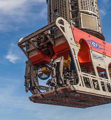
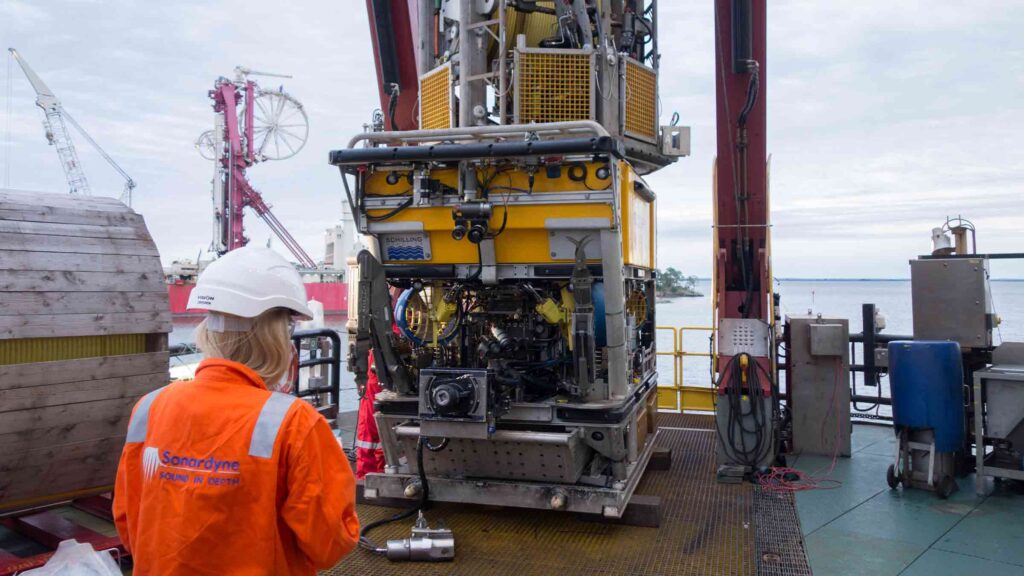
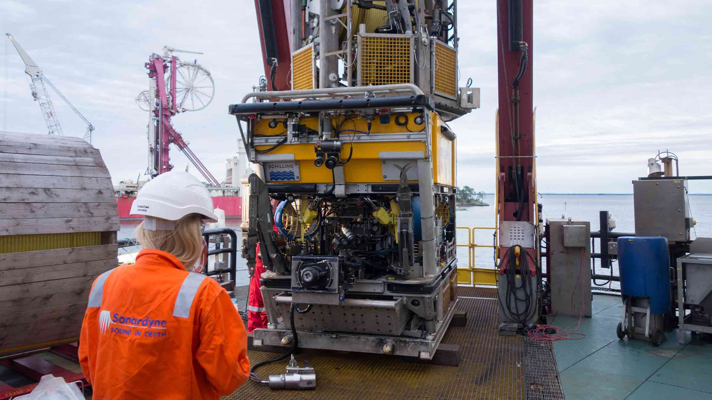
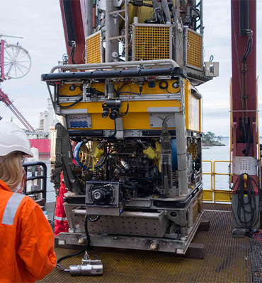
Engineered for Work-class ROVs
Overview
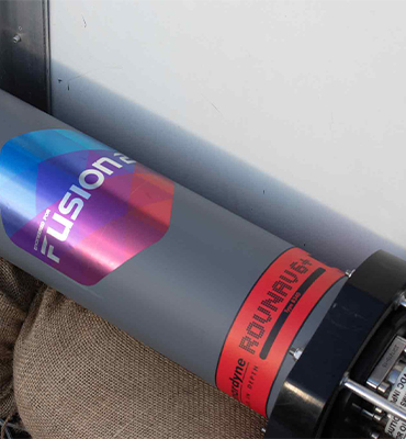
ROVNav 6 has been superseded by ROVNav 6+
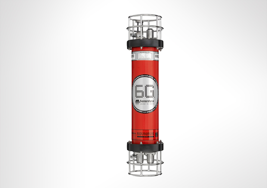
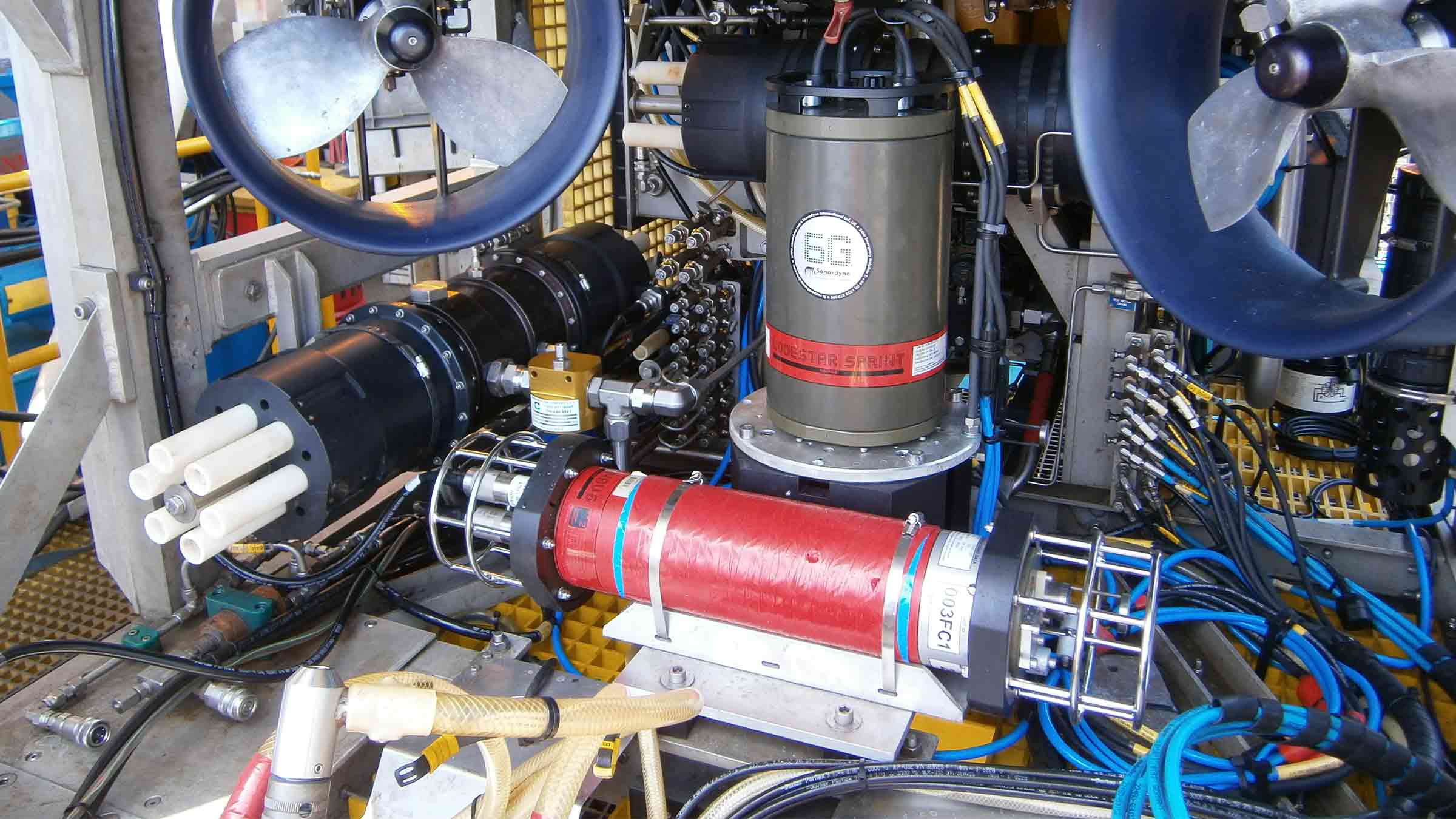
ROVNav 6 is a 6G Wideband 2 ranging LBL ROV Transceiver and telemetry transceiver specifically designed for installation on work class ROVs.
At a glance
- Use it with Fusion 6G
- Wideband 2 enabled
- High power, long range LBL transceiver
- 3,000, 5,000 or 7,000 m depth rated
- USBL mode for emergency ROV relocation
- Modem mode for harvesting data from Sonardyne sensors

Specifications table
| Feature | 8310-3161 | 8310-5261 | 8310-7261 | |
|---|---|---|---|---|
| Depth rating | 3,000 m | 5,000 m | 7,000 m | |
| Operating frequency | MF (20–34 kHz) | MF (20–34 kHz) | MF (20–34 kHz) | |
| Transducer beam shape | Omni-directional | Omni-directional | Omni-directional | |
| Transmit source level (dB re 1 µPa @ 1 m) | 187–196 dB (4 Levels) | 187–196 dB (4 Levels) | 187–196 dB (4 Levels) | |
| Tone Equivalent Energy (TEE) | 193–202 dB | 193–202 dB | 193–202 dB | |
| Receiver sensitivity (dB re 1 µPa) | 90–120 dB | 90–120 dB | 90–120 dB | |
| Range precision | Better than 15 mm | Better than 15 mm | Better than 15 mm | |
| Serial communications (software programmable) |
Primary port | RS232 or RS485 (half-duplex) | RS232 or RS485 (half-duplex) | RS232 or RS485 (half-duplex) |
| Secondary port | RS232 or RS485 (half-duplex) or SYNC IN | RS232 or RS485 (half-duplex) or SYNC IN | RS232 or RS485 (half-duplex) or SYNC IN | |
| Battery life Li-ion (listening) | 3 days | 3 days | 3 days | |
| Operating voltage | 24 or 48 V dc (±10%) | 24 or 48 V dc (±10%) | 24 or 48 V dc (±10%) | |
| External power | Active (listening) | <3 W typical (maximum 10 W when charging) | <3 W typical (maximum 10 W when charging) | <3 W typical (maximum 10 W when charging) |
| Peak (during transmission) | <80 W | <80 W | <80 W | |
| Serial communications connector | AGP (8-way female) |
AGP (8-way female) |
Subconn (8-way female) |
|
| Remote transducer connector | AGP (4-way male) | AGP (4-way male) | Burton (3-way male) | |
| Housing mechanical construction | Hard anodised aluminium 6082 |
Hard anodised aluminium 7075 |
Hard anodised aluminium 7075 |
|
| Remote transducer mechanical construction | Stainless steel 316 | Stainless steel 316 | Stainless steel 316 | |
| Dimensions (maximum) (length x diameter) | 768 x 200 mm | 768 x 200 mm | 768 x 200 mm | |
| Housing diameter | 134 mm | 134 mm | 140 mm | |
| Weight in air/water | Housing assembly | 14.3/5.3 kg | 14.7/5.7 kg | 15.5/6.0 kg |
| Transducer | 3.2/2.7 kg | 3.2/2.7 kg | 3.3/2.8 kg | |
| Cable (5 m) | 2.7/1.4 kg | 2.7/1.4 kg | 2.7/1.4 kg | |
| Sensors | ||||
| Temperature (±0.1°C) | Standard | Standard | Standard | |
| Strain gauge pressure sensor (±0.1%) | Standard | Standard | Standard | |
| High precision strain gauge (±0.01%) | Optional | Optional | Optional | |
| Inclinometer (tilt sensor) Range ±90°, accuracy: ±1° (vertical orientation) |
Standard | Standard | Standard | |
| Sound velocity sensor ±0.02 m/s accuracy under calibration conditions |
Standard | Standard | Standard |
Frequently asked questions
STP files
Datasheets
Unlocking the Gulf Loop Current
The Gulf of Mexico is home to one of the world’s most energetic oceanographic phenomena – the Gulf of Mexico Loop Current. Reaching intensities of between 2 – 4 knots and measurable down to 1,000 m, the Loop Current System (LCS) also regularly sheds Loop Current Eddies (LCE).
The challenge
LCEs are highly energetic anticyclonic (clockwise) rotating rings of warm water, roughly 300 km across and 500 – 1,000 m deep, with current speeds of up to 4 knots. These break away from the extended Loop Current about every 8-9 months and slowly drift west-southwestward towards Texas or Mexico at about 3-5 km per day.
When an LCE forms at the height of hurricane season, it has the potential to fuel rapid intensification of hurricanes. This is what happened in 2005, just before Hurricane Katrina passed over and “bombed” into a Category 5 hurricane.
Warm circulating eddies can break off the LCS into the western, northern and central Gulf. These eddies are so highly energetic that they regularly disrupt oil and gas operations. But, they’re also critical to the Gulf of Mexico’s oceanographic system, including its nutrient and food cycles and, most importantly, hurricane intensity.
Despite 50 years of effort by the scientific community to understand the processes underlying the LCS, its behaviour remains unpredictable. To some extent, this is because of interactions with the deep eddies, which have been difficult to track from measurements near the sea surface. For this reason, a multi-year scientific study has been launched, led by the University of Rhode Island(URI). It includes a major deployment of Sonardyne’s Pressure Inverted Echo Sounders(PIES).


The solution
Following a recommendation by the US National Academies of Sciences, Engineering, and Medicine a long-term, US$ multi-million research program to plug the gaps in understanding and predicting the LCS is now underway.
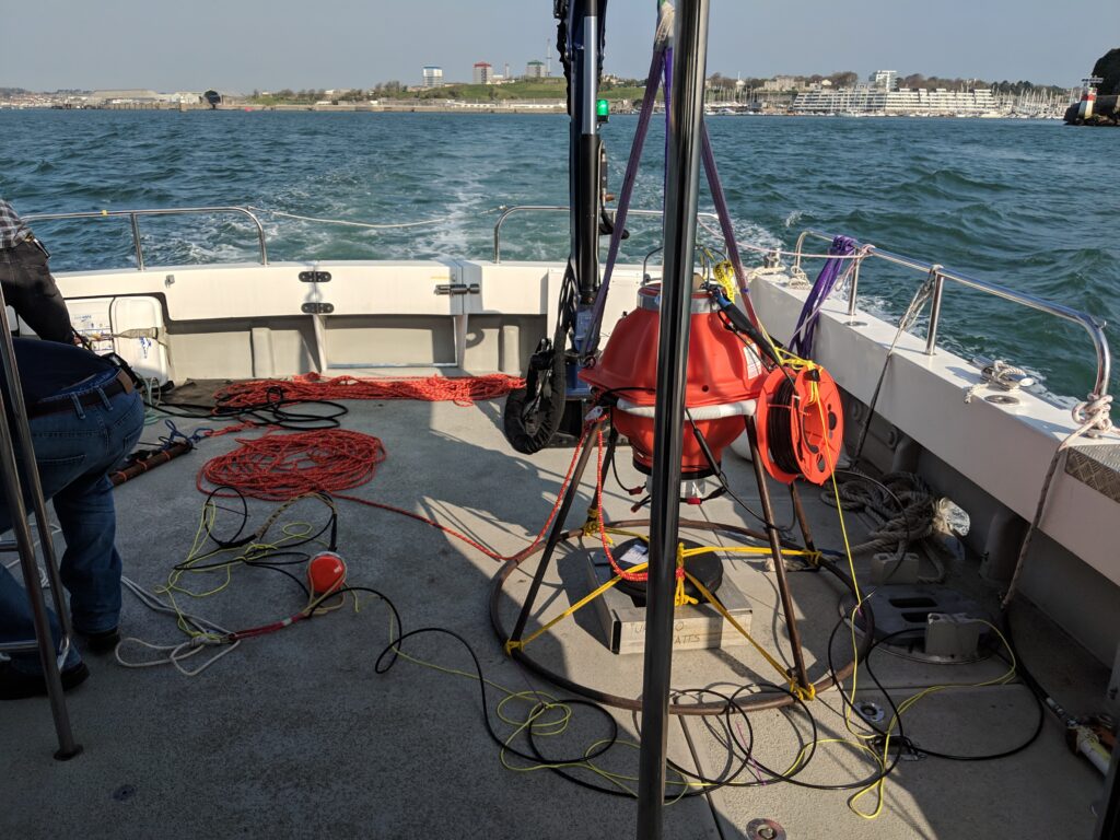
The initial two-year project comprises an array of 15 URI CPIES, five Sonardyne CPIES and five Bureau of Ocean Management PIES. These are in an array, spaced 60 km apart, at depths down to 3,500 m in the area of the extended LCS. Initially deployed in June 2018, for a nominal two-year study, the units are fitted with batteries that can keep them powered for up to 36 months. This will allow for data gathering continuity in the event of a subsequent expansion of the program.
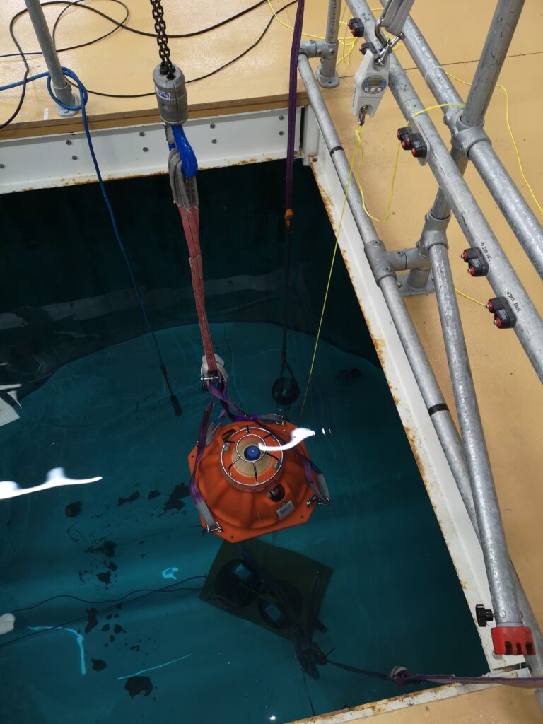
A core element of this scientific study is the array of seabed-mounted sensors, including Sonardyne’s PIES. PIES were originally developed for the marine seismic industry to measure average sound velocity in the water column. They do this by transmitting a wideband acoustic pulse from their position on the seabed. This pulse is reflected off the sea surface and returns to the seabed where it is detected by the PIES.
Oceanographers, however, use PIES differently. Their goal is to derive important physical data, including the strength and direction of currents. This is based on the principle that there’s a strong correlation between two-way travel time (usually known as tau) and vertical profiles of temperature, salinity and density. As a consequence, where this profile has been derived from historical data, an empirical relationship can be derived, which enables the density profile to be inferred from tau.
At a basic level, a laterally separated pair of PIES will, therefore, provide a vertical profile of velocity, and by deploying an array of PIES, local horizontal velocity and density fields can be mapped over the period of deployment.
URI has pioneered and refined the use of PIES for this purpose. While URI has a long history of developing its own PIES instruments, it decided to use Sonardyne’s PIES, as well as its own. This was primarily because a comparison study off the coast of Oregon* indicated that the Sonardyne PIES could generate similar accuracy data efficiently, potentially enabling longer deployments – and because of their telemetry capability.
Sonardyne’s integrated high-speed (up to 9,000 bps) acoustic telemetry capability also enables remote reconfiguration of the instruments and wireless retrieval of data to surface vessels, without interrupting the bottom pressure record.
These capabilities are based on Sonardyne’s extensive expertise in underwater acoustics, signal processing, hardware design and custom engineering, which URI recognises, have the potential to reinforce future PIES development.
Sonardyne’s expertise was central to reconfiguring a standard PIES as a CPIES (Current PIES) which was needed for this project to allow for near-seabed current data to be harvested alongside the PIES pressure and tau measurements. It also delivers important data on deep eddy currents above the seabed/water interface.
The reconfiguration involved connecting an Aanderaa Doppler current sensor to the PIES, which then served as a battery pack and data logger for the current sensor, deployed 50 m above the PIES on a float. Combining the deep current observations with the deep pressure observations enable data from the array to be referred to a common reference surface.
The results
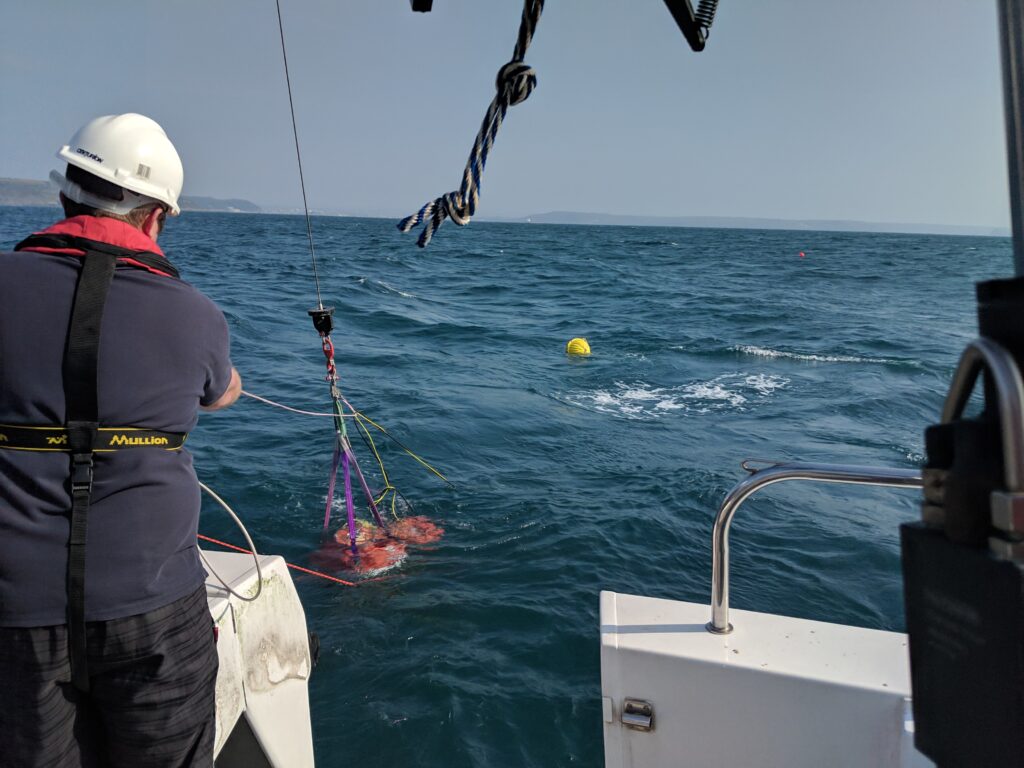
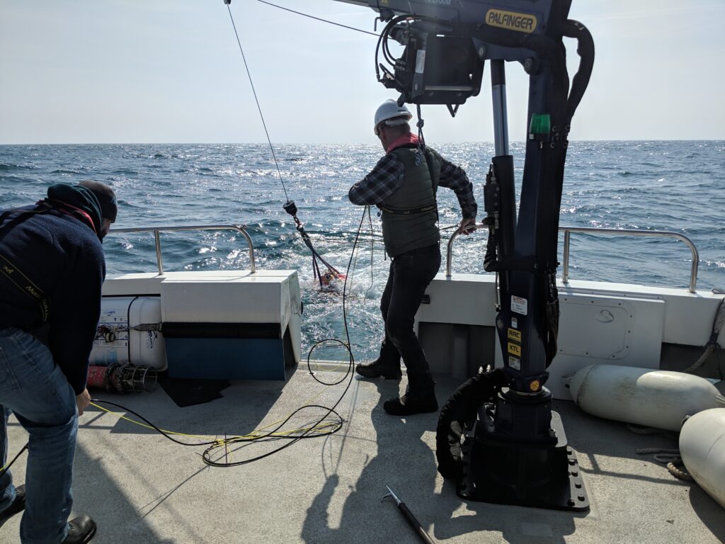
An interim data retrieval campaign, using acoustic telemetry, was successfully completed in September. While the principal purpose of this was to recover an initial three-month-long data set, one notable feature found in the data was echoes, thought to be from fish, shrimp or squid.
This has been seen in other studies carried out by URI. We believe it is related to the transport of nutrients by deep currents crossing from the deeper to shallower thermocline side around the periphery of the Loop Current or a passing LCE.
The present array will inform planning for a longer-term, 10-year campaign. This could see a substantially expanded array of PIES deployed into Cuban, as well as Mexican and US waters. The aim of this larger array would be to provide near real-time data as input for LCS forecasting models.
Loop Current and LCE forecasts have the potential to benefit a wide range of users, from oil and gas operations and hurricane forecasters to fishing and tourism. Furthermore, improving ocean modelling in the Gulf of Mexico has the potential to provide a standard for improving prediction efforts in other ocean basins also.
GPR – Acoustics unlock a new approach to seabed geodetics
Autonomous and uncrewed marine platforms are transforming the way in which we acquire and analyse data from our oceans. Our technology is assisting with seafloor geodesy, an emerging scientific field that is making the real-time study of continental plate tectonics a cost-effective and viable option.
The challenge
Seafloor geodesy projects are underway across the globe, all in pursuit of a better understanding of earthquakes, tectonic processes and tsunami hazards, and ultimately to save lives. In addition, the technology is being applied within the offshore oil and gas industry to mitigate risk through better ongoing surveillance during the producing life of a field.
But tracking seafloor and oilfield infrastructure movement at minute scale resolution through two miles of seawater is far easier said than done. Delivering the results straight to an analyst’s desk anywhere in the world takes a little more know-how than the GPS and laser methods we are used to seeing on terrafirma.
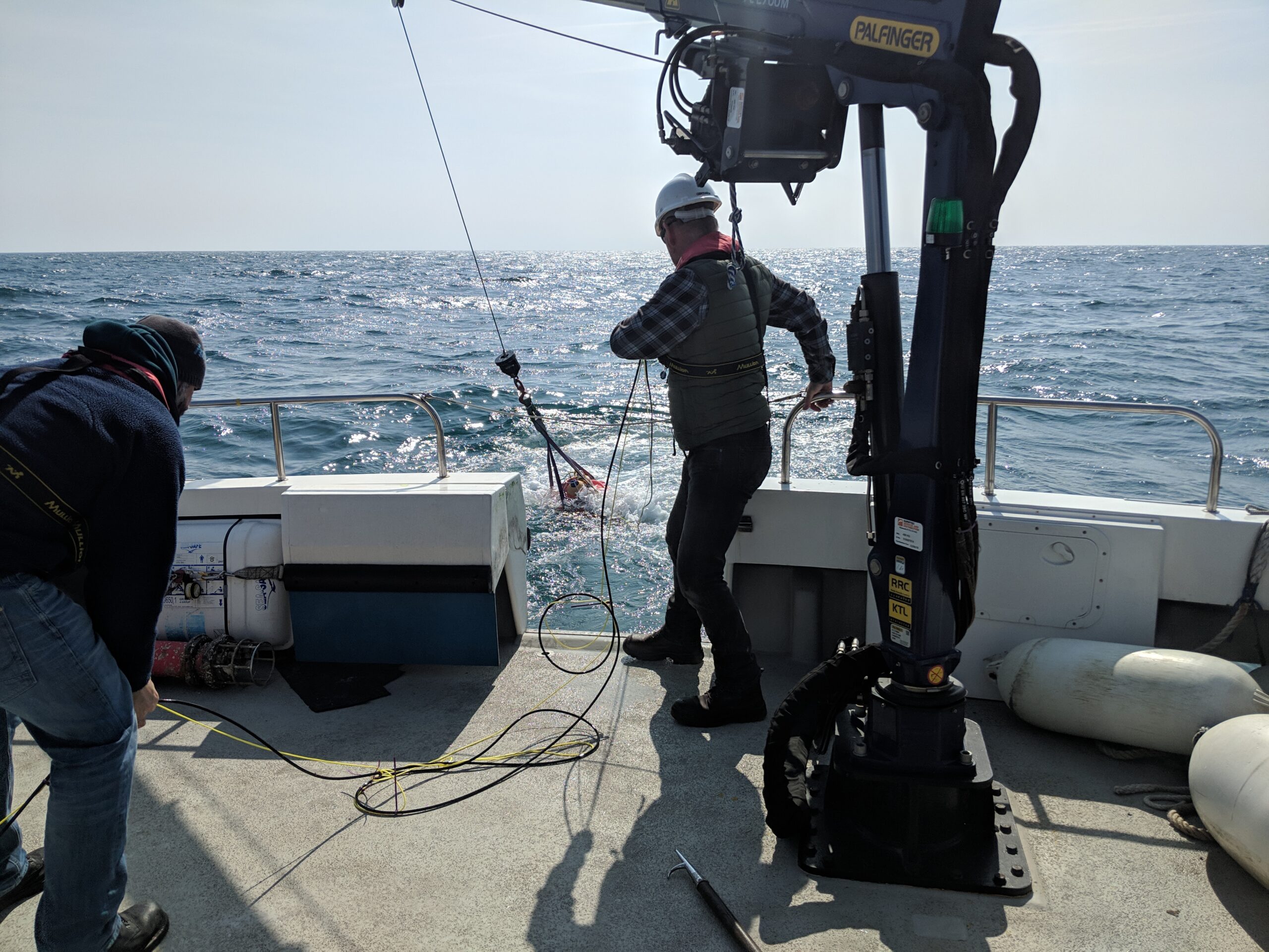
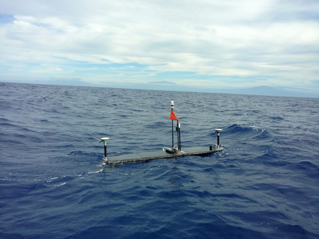
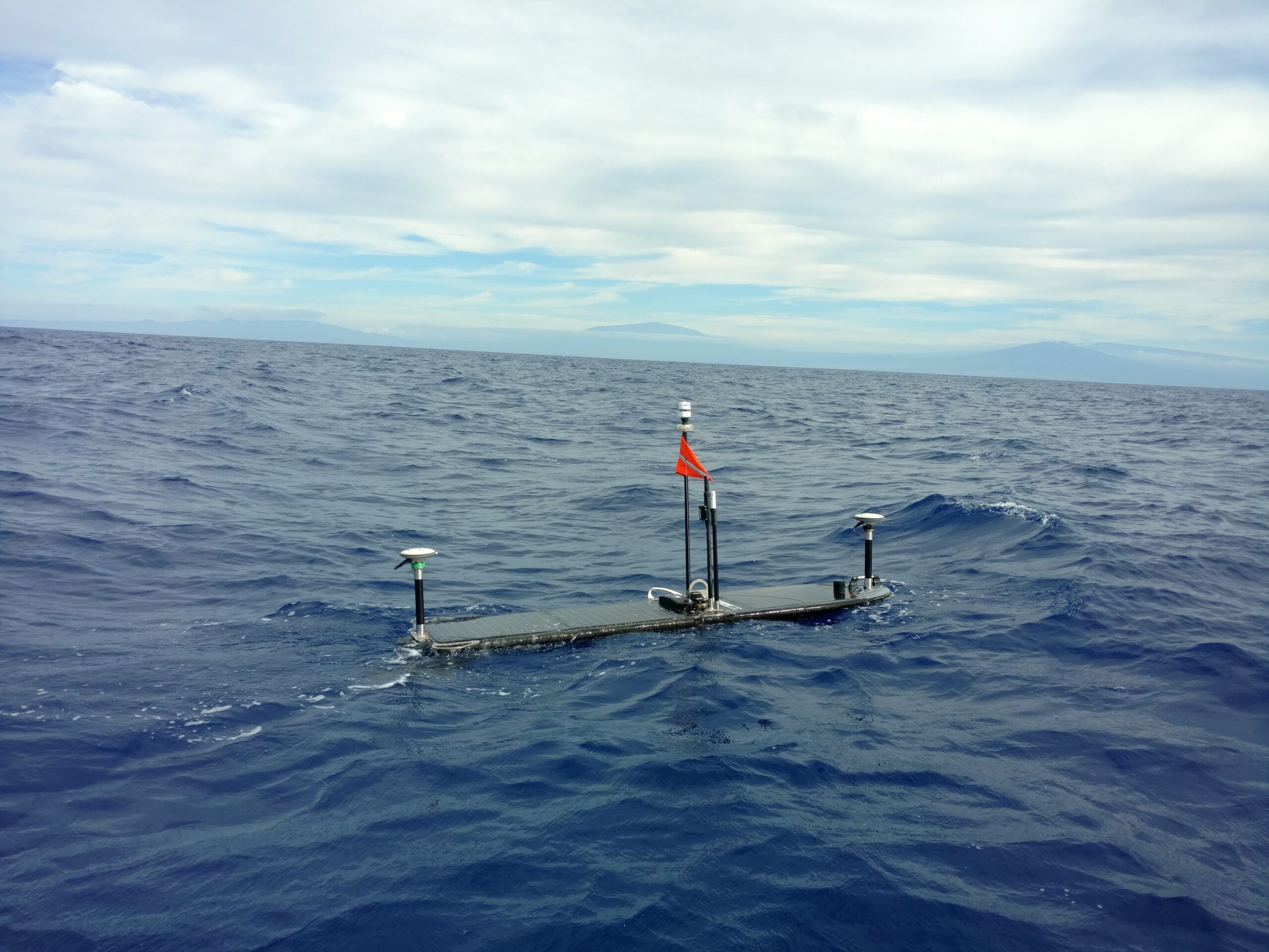
The satellite-based GPS and laser methods used on land don’t work in the ocean, so researchers are turning to a technique that’s referred to as GPS-Acoustics (GPS-A). While it’s possible to do these surveys using a vessel, unmanned surface vehicles (USV) like the Liquid Robotics Wave Glider and long endurance Sonardyne surveillance technology offer a more cost-effective solution to making GPS-A measurements.
To be able to accurately position a subsea transponder, you must first be able to accurately position the USV. This can be cost-inhibitive when it comes to academic studies. Similarly, oilfield asset monitoring becomes costly and impractical when relying on a combination of manned and unmanned vessels for visual observations and creep measurement.
Gathering seabed geodetic data is difficult, slow, expensive and not without risk to the people sent out to get the job done.
The solution
With long endurance instruments, such as Sonardyne’s Ambient-Zero-Ambient (AZA), which overcomes the inherent problem of pressure sensor drift, and a Wave Glider at the surface to position the transponders and transmit the data, there is now a viable alternative that provides near real-time awareness of plate tectonic activity.
Sonardyne’s Autonomous Monitoring Transponder(AMT) instrument is designed to autonomously and precisely measure horizontal and vertical displacement using thousands of range (distance between pairs of transponders), pressure (depth), sound velocity, and inclination measurements. Each unit runs a fully automatic data gathering and logging regime and can remain continuously deployed for up to 10 years.
Throughout a mission, the Wave Glider GPS-A payload records GPS logs in Receiver Independent Exchange (RINEX) format; a data interchange format for raw satellite navigation system data. This is a critical and unique part of the system’s ability to achieve millimetric precision.
By taking the GPS RINEX files and post processing this data with the corrected orbital paths of the GPS satellites themselves, it is possible to reduce the Root Mean Square (RMS) of the positioning by up to 30 times compared to typical GPS receiver accuracy.
Table 1 shows an Easting and Northing position scatter plot for an unmanned surface platform before (blue) and after (red) GPS-A post processing. The data was captured during a trial at Sonardyne’s research facility in Plymouth.
Similarly in Table 2, the plot shows a surface height comparison over a complete tidal cycle. Once again, the data in blue shows the raw observations, whilst the data in red provides the RINEX post processed results.
With these advances in technology, seafloor geodesy projects have sprung up around the world, in particular around the Ring of Fire in the Pacific basin where some of the most powerful earthquakes originate.
Study of the Cascadia Subduction Zone, research into the workings of the Mentawai Seismic Gap and geodetic observations of the Nazca-South American Plate Boundary are all using technologies developed by Sonardyne and Liquid Robotics.
Dr. David Chadwell of Scripps Institute of Oceanography selected Sonardyne’s Fetch instrument for the seabed component of his study of the Cascadia Subduction Zone. The Fetch has functionally equivalent to the AMT but with a much bigger battery that enables 10 year deployments. This has provided a more cost-effective platform to collect data. Their original plan to use a diesel powered buoy was also upgraded when the advantages of the Wave Gliders in terms of mobility and longevity were recognised.
Studies of the Mentawai Seismic Gap by Dr. Sylvain Barbot, Dr. Emma Hill, and Dr. Sharadha Sathiakumar of the Earth Observatory in Singapore, is being supported by quipping Wave Gliders with GPS-A technology. This is enabling them to monitor seafloor deformation off the coast of Sumatra. An unmanned platform is essential, as regular surveys using research vessels are just too expensive.
The Nazca-South American Plate Boundary has had a seafloor geodetic network of AMTs installed at key points ranging in depth from 2,600 – 6,000 metres. Rather than using absolute GPS-A measurements, the relative movement of the AMTs to each other is measured using the on-board pressure sensors and acoustic ranging between the AMTs.
The other key component of the Nazca-South American Plate Boundary network is a GPS-A equipped Wave Glider. Operating autonomously at the surface, the vehicle holds position above the seafloor stations, monitors system health, uploads data from the seafloor node, and transfers it back to shore via satellite – allowing the research vessel to focus on other more valuable tasks and facilitating the cost-effective retrieval of data from the seafloor.
The results
The impact of the technologies developed by Sonardyne and Liquid Robotics goes far beyond simply providing a cost-effective alternative to crewed vessels. As researchers pursue breakthroughs in earthquake and tsunami early warning systems, platforms like USVs may ultimately save lives.
These solutions are proven and ready for deployment today. Already they are broadening our knowledge of the deep ocean, geodetic data and the seismic relationships that impact coastal populations and oilfield asset monitoring.
Overview
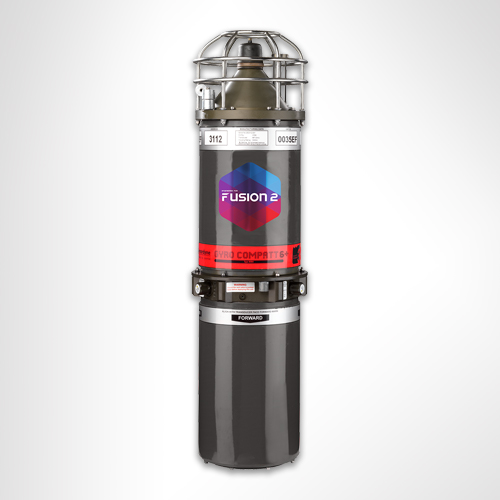
Designed for Work-class ROVs
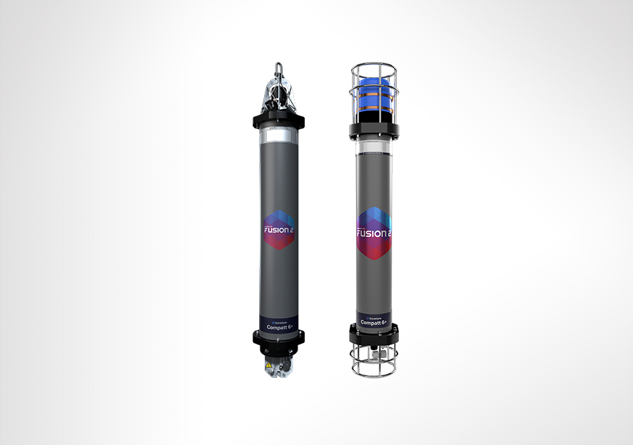
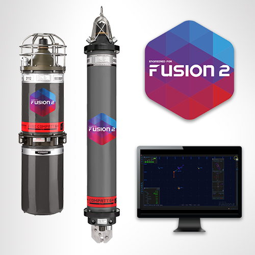
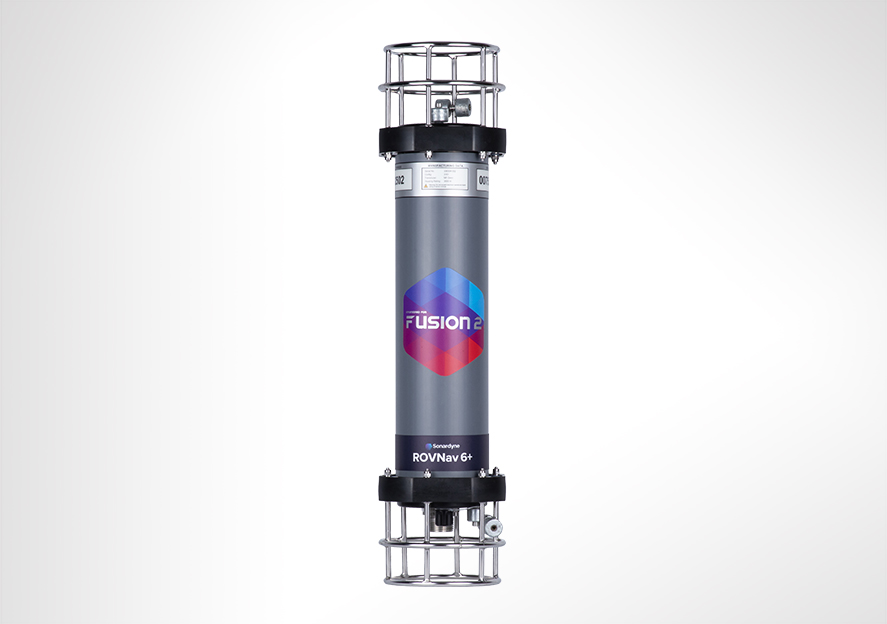
ROVNav 6+ (plus) is a Wideband 3 and Wideband 2 ranging LBL and telemetry transceiver specifically designed for installation on work-class ROVs. ROVNav 6+ is suitable for pipeline positioning, seabed deformation monitoring and metrology.
Overview
ROVNav 6+ uses our new Wideband 3 signal technology, which is key to unlocking the benefits of your Fusion 2 LBL system.
It allows, for the first time, sensor telemetry data (e.g. pressure, depth or temperature) from a seabed or structure deployed Compatt 6+ to be embedded within navigation (ranging) data. This change has a big impact on operations such as structure installation, as breaks in tracking to get sensor reading updates at vital moments are now a thing of the past.
Its compatibility with Wideband 3 and Wideband 2 telemetry commands, and support of high power Wideband 2 ranging protocols, proven for their accuracy and robustness, means the ROVNav 6+ offers improved range and acoustic performance in challenging conditions such as on noisy vehicles or in multipath environments.
At a glance
- High power, long range LBL transceiver for ROVs
- Wideband 3-enabled supporting embedded sensor data with ranging data
- Optimised for Fusion 2 and compatible with Fusion 1
- 3,000, 5,000 or 7,000 m depth rated options
- USBL mode for emergency ROV relocation
- Modem mode for harvesting data from Sonardyne logging sensors; Fetch, AMT…
ROVNav 6+ is also a fully functional USBL responder or transponder, compatible with Wideband 2 USBL systems and HPR400. The internal li-ion rechargeable battery pack also enables emergency transponder mode, so if the umbilical and therefore power is cut to the ROV it can still be located by USBL.
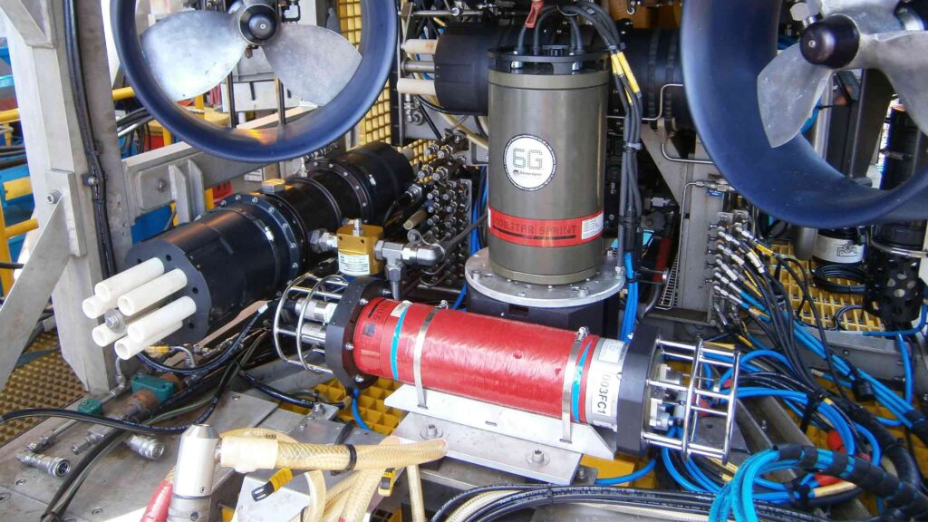
The omni-directional remote MF transducer makes installation on an ROV easy. ROVNav 6+ is designed to be rugged and relatively lightweight and utilises robust underwater connectors. ROVNav 6+ supports a range of internal sensors including: strain gauge pressure, PRT temperature and MEMS based inclinometer.
ROVNav 6+ is also fully compatible with our modem and logging equipment such as AMT and Fetch products, allowing it to be used to retrieve data or configure logging regimes. It supports all of our Wideband 2 and Wideband 3 spread spectrum acoustic communication; 100 to 9,000 bps data rates can be selected depending on the environment.
Sensor options include a Digiquartz pressure sensor, precision inclinometer and altimeter interface. This provides a fully featured ROV manipulator deployable tool/sensor pack for a range of different applications including metrology, bathy survey and structure deployment operations, without the requirement for any additional interfacing on the ROV.
Specifications table
| Feature | 8340-3161 | 8340-5261 | 8340-7261 |
|---|---|---|---|
| Depth Rating | 3,000 m | 5,000 m | 7,000 m |
| Operating Frequency | MF (20–34 kHz) | MF (20–34 kHz) | MF (20–34 kHz) |
| Transducer Beam Shape | Omni-directional | Omni-directional | Omni-directional |
| Transmit Source Level (dB re 1 µPa @ 1 m) | 187–196 dB (4 levels) | 187–196 dB (4 levels) | 187–196 dB (4 levels) |
| Range Precision | Better than 15 mm | Better than 15 mm | Better than 15 mm |
| Serial Communications | RS232 or RS485 (half-duplex) | RS232 or RS485 (half-duplex) | RS232 or RS485 (half-duplex) |
| Battery Life Li-ion (Listening) | 3 days | 3 days | 3 days |
| Operating Voltage | 24 or 48 V dc (±10%) | 24 or 48 V dc (±10%) | 24 or 48 V dc (±10%) |
| Serial Communications Connector | Subconn (8-way female) | Subconn (8-way female) | Subconn (8-way female) |
| Remote Transducer Connector | Burton (3-way male) | Burton (3-way male) | Burton (3-way male) |
| Housing Mechanical Construction | Hard anodised aluminium 6082 | Hard anodised aluminium 7075 | Hard anodised aluminium 7075 |
| Remote Transducer Mechanical Construction | Stainless steel 316 | Stainless steel 316 | Stainless steel 316 |
| Dimensions (Maximum) (Length x Diameter) | 768 x 200 mm | 768 x 200 mm | 768 x 200 mm |
| Weight in Air/Water | 14.3/5.3 kg | 14.7/5.7 kg | 15.5/6.0 kg |
Frequently asked questions
If I’m using Fusion 2, can I choose to use Wideband 2 or Wideband 3 telemetry?
Can ROVNav 6+ be used with standard Compatt 6s?
Will my ROVNav 6 work with Fusion 2?
Do I need to upgrade to Compatt 6+ and ROVNav 6+?
Where should I install my ROVNav 6+ transducer?
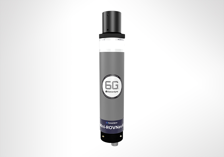
What are the differences between a ROVNav 6+ and Mini ROVNav 6+ ?
How to QC a Sound Velocity (SV) in Fusion 2
How far can my Compatt 6+ be above the seabed?
How do I perform an LBL calibration in Fusion 2?
STP files
Software and firmware
Transponders
Datasheets
Manuals and quick start guides
Technical bulletin
Did you know?
ROVNav 6+ is compatible with Fusion 1 and can be depth rated up to 7,000 m