Origin 600 draws 0.625 mA when sleeping, 25 mA when pinging, and 0.146 A when fully active.
The above currents have been calculated using P / V = I, where P = power, V = voltage and I = current.
The Origin 600 ADCP requires 18-48 V external power, so 24 V was taken as a standard voltage. Its power consumption is 15 mW while sleeping, 600 mW while pinging, and 3.5 W when fully active.
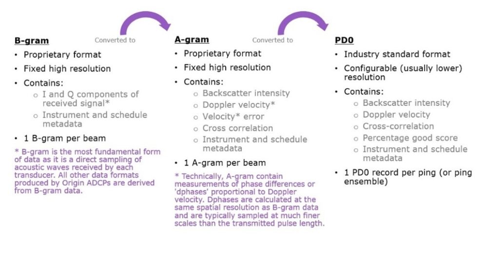
Origin produces acoustic data in three different file formats: PD0, A-gram, and B-gram. Each format is a binary file format that is not human-readable.
What is PD0?
We have a separate FAQ giving more detail on PD0 (which can be found here), but essentially, this is a binary, industry-standard data format that describes the velocity profile measured by the ADCP as a function of depth, along with other parameters such as backscatter intensity, derived metrics, and metadata.
What is A-gram?
A-grams are a binary format proprietary to Sonardyne ADCPs. Each A-gram contains water velocity data sampled along the slant range of a single beam, along with other parameters (such as backscatter intensity), derived metrics, and metadata. One A-gram contains information pertaining to one beam. Thus, for a single ping, Origin 600 will produce five A-grams, one for each beam.
A-gram water velocities are always logged in beam frame
Origin logs A-gram to disk if requested within the mission configuration
A-gram can provide up to factor 40 improvement in spatial fidelity compared to PD0 format velocity profiles
All A-gram files are identified by a ‘.agram’ extension
What is B-gram?
B-grams are a binary format proprietary to Sonardyne ADCPs. Each B-gram contains raw acoustic data sampled along the slant range of a single beam, along with metadata. One B-gram contains information pertaining to one beam. Thus, for a single ping, Origin 600 will produce five B-grams, one for each beam.
Origin logs B-gram to disk if requested within the mission configuration
B-gram can provide up to factor 40 improvement in spatial fidelity compared to PD0 format files
All B-gram files are identified by a ‘.bgram’ extension
How do A-gram and B-gram differ from PD0?
Like PD0, A- and B-gram hold common metadata. Formats differ by the extent to which data has been processed. It is possible to transform between the different data formats, but only in the order described below. It is not possible to convert from PD0 data to A-gram or B-gram, nor is it possible to convert from an A-gram to a B-gram.
When Origin pings and captures data, in the first processing step B-gram data is stored in memory. Each B-gram contains raw samples of the backscattered sound waves received by one beam. In the second processing step, the data content of a B-gram is processed to form the data content of an A-gram corresponding to that same beam. In the final processing step, once A-grams have been computed for all beams for that ping, they are binned into depth cells to produce one PD ‘ensemble’.
It is possible to connect acoustically with Origin both on dry land and with the ADCP in water. If you’re having trouble doing this, read on for some tips that should help you establish acoustic communication.
First steps
It’s important to determine the address of the Origin in-built acoustic modem before attempting any acoustic communications. The modem address can be found and (if necessary changed) from Origin Portal. You can also find the address when the ADCP is deployed if necessary. This can be done using an iWand or through the 6G terminal.
The desktop PC software Origin Topside provides an interface to communicate acoustically with Origin. Before attempting acoustic communications, the latest version of the Origin Topside software should be installed on the PC.
If you can’t connect to an ADCP in the water
Topside acoustic modem
We have a number of topside transponders to suit different conditions. The first thing to check is that you’re using a compatible topside acoustic modem, for example an Origin Nano Dunker or an HPT 3000, and that this has sufficient power.
Angle of approach
The in-built Origin 600 modem has a typical slant range of around 500 m which should be accounted for when positioning a vessel or buoy for communications with Origin. While the ADCP modem has an omnidirectional beam, its angled position on the Origin 600 endcap means there is an optimal direction in which to approach the ADCP for acoustic communications (i.e., in the direction of the modem transducer face). If you can’t connect to the ADCP, try approaching from a different direction, or getting closer to the deployed ADCP. You should also make sure that there is nothing obscuring the line of sight to the ADCP.
Range in Origin Topside
In Origin Topside there is an entry field where you can type the approximate depth and range to the deployed ADCP. It is important to get this range as close as possible to reality, so if you can’t connect to your ADCP, try adjusting the numbers in this field. The range needs to be large enough to encompass the distance to the ADCP, but not so large that it adds gain to the topside transceiver and causes saturation. If you enter a range that is much too small, the command won’t be heard by the ADCP modem.
Modem address
Make sure you’ve typed in the correct modem address in Origin Topside for the remote ADCP.
For more information on any of these issues and to see how to solve these issues in practice, see the FAQ section in the back of the Origin Topside manual.
If you can’t connect to the ADCP on land
There are a number of things you can check if you can’t connect to the Origin 600 ADCP on land.
Check that the battery disconnect has been removed.
Plug in Power over Ethernet or DC power as the battery may be depleted (you will not be able to communicate with the ADCP if the battery is flat).
Check whether the ADCP status LED is flashing, indicating that it’s awake. LED off or flashing very slowly indicates that the device is asleep.
Make sure you are using the correct acoustic modem address. If you aren’t sure what this is, you can check it via Origin Portal (connect to the ADCP using a cable) or by using iWand.
Make sure the nano you’re using to communicate to the ADCP with is close to the modem – it shouldn’t be more than 0.5-1m away in air.
Make sure the nano is at a good angle/position to the ADCP, not off to the side.
These tips should help if you’re having issues connecting to your ADCP, but if you need further assistance, please feel free to reach out and we’ll be happy to help.
Data stored on Origin 600 can be easily accessed in two ways: acoustically, or via an Ethernet cable directly to your laptop.
Accessing data via a cable
To access data stored on an Origin 600 via an Ethernet cable, follow the steps below. If you would prefer to see these steps in a follow-along video format, please visit this video on Sonardyne’s YouTube channel.
Connect the breakout cable that is supplied with every Origin 600 ADCP to the wet connector on the device.
Use an ethernet cable to connect the breakout cable to your laptop.
Remove the battery disconnect from the ADCP to power it up. If the internal battery has been fully depleted, you will need to recharge it first. Use the supplied Power Over Ethernet (POE) injector or hook it up to a DC power supply using the banana sockets on the breakout box.
Once the ADCP is awake, navigate to 192.168.179.20 on your web browser, and press return. This will connect you to Origin Portal, the ADCP’s built in, embedded web user interface.
On the left, you will see 5 purple squares. The 5th one down of these will take you to the data page where you will find an FTP URL – this is the location of the ATP file system. Copy the URL and paste it into the file explorer on your laptop, then press return. You will then see the folders of data stored on the ADCP.
Drag the folders of data that you want on to your laptop’s desktop, and the transfer will happen automatically. You don’t need to transfer all the data; you can copy files from an individual mission, an individual schedule, an individual file format, or even just a single file as required.
Accessing data acoustically
Due to the limited bandwidth of acoustics, it is not possible to acoustically download log files of native formats of Origin data (PD0, A-gram, and B-gram), or files of external sensor data. However, it is possible to acoustically download individual records of PD0 data via Origin Topside or Edge processed data.
To download data acoustically:
Connect the topside modem to the PC running Origin Topside
Connect Origin Topside to the remote ADCP
Navigate to the data page and browse the ADCP for the data file(s) you want to download
You can also view the latest PD0 ensemble via a dialogue box that shows beam-frame PD0 velocities, intensities, and cross-correlation scores (x-axis) against depth (y-axis).
For detailed instructions on how to download your data acoustically, request the Origin Topside User Manual here
When preparing beacons for deployment, it is important to ensure that they have sufficient remaining battery capacity for the intended deployment, and to consider the most appropriate beacon addresses.
The first important decision is whether the WB2, or WB2+ signal set is most appropriate. Note that the ‘+’ on the end of WB2 does not mean ‘better’, it indicates longer signals, which carries with it higher battery consumption, and potentially more reverberation noise in the water. WB2 signals should be the default choice unless there is a specific reason to choose WB2+.
It is usually more effective to tune power and gain than using longer signals; however longer signals are useful at the margins of detectability.
Sonardyne can provide support in predicting battery life given an expected signal set, power level, interrogation, and telemetry rate.
Our Deployment Machine, when correctly braced, is capable of handling prolonged speeds of 7 knots.
However, if the pole is accidentally left deployed, and the vessel sails to its next destination at a speed greater than this, then potentially‑catastrophic damage could result.
At best the pole could deform and bend, resulting in a replacement Deployment Machine and Transceiver.
At worst, the through-hull tube on which the Gate Valve sits could fail, possibly resulting in (at best) localised flooding.
Our most-recent Deployment Machine system, together with our latest Marksman and Ranger2 software, allows not only the machine to be operated from software (as well as from the normal push‑buttons on each control console), but also to warn the operator if the Deployment Pole is not fully recovered when the vessel exceeds 7 knots.
The following alarm message is displayed: “Deployment 1 is in the down position and vessel speed has exceeded the safety threshold of 7 knots”.
(“Deployment 1” is the default (changeable) name of the Deployment Machine.)
As well as alerting the operator both visually and audibly from Marksman/Ranger2 software, a telegram can also be configured to alert 3rd party equipment, such as the DP system – either via a serial (RS232/RS485) or UDP link.
Please contact us at [email protected] to discuss how we can provide this valuable safety feature.
At Sonardyne, we’re dedicated to ensuring the reliability of our equipment for your peace of mind. That’s why we’re offering a specialised health check service for your WSM6+ transponders.
Why a health check?
Maintain original parameters: Ensure your devices stay true to their original specifications.
Consistency with specifications: We check every aspect to guarantee consistent performance.
Prevent deployment damages: Our thorough inspection identifies and prevents potential damages that could compromise your operations
Our promise to you
Preventive care: This is our opportunity to identify any potential issues before they arise, safeguarding your operations.
Detailed report and certification: We provide a comprehensive report and a certificate, confirming the state of your unit.
Value for money: Investing in a health check to keep your WSM6+ in optimal condition will help to: Extend its working life, avoid the cost of delayed / aborted operations due to product failures, delay the cost of replacing equipment.
What does the health check include?
Comprehensive inspection of all key components.
Sensor parameters check and adjustment if necessary.
Tank test and in water performance checks
Bench and soak testing in control environment.
Detailed analysis and feedback.
Who do I contact?
Don’t wait until it’s too late! To ensure your transponders are in optimum condition, contact us to schedule your WSM6+ health check today!
Prevent costly downtime – act now before it’s too late!
Are you risking your offshore operations? In the challenging world of marine projects, hidden dangers in your machinery could lead to damaging breakdowns. Don’t wait until it’s too late!
Don’t let minor issues turn into major downtime. Schedule your Sonardyne Health Check during your next vessel service window.
Our expert team is ready to visit your vessel or rig, conduct a thorough assessment, and ensure you are fully prepared for your next mission.
Without appropriate maintenance your operation could be one malfunction away from downtime.
Imagine this: a single malfunction in an uninspected bronze bearing could trigger a system failure, causing downtime and financial loss…
What could potentially happen if your systems are not regularly serviced?
Unexpected downtime: Unsuspected issues can lead to significant project delays, missed deadlines and increased costs.
Safety hazards: Unmaintained equipment can pose serious risks to your crew and the environment.
Financial loss: Emergency repairs and unscheduled maintenance cost far more than routine checks.
Don’t let this happen to you!
We are here to help you avoid these pitfalls with our comprehensive Health Check service. Whether your vessel is coming back into service, getting ready for a new mission, or simply needs a review, we would love to arrange a visit.
Cost-saving advantages.
The potential costs of a breakdown and the subsequent vessel downtime could run into thousands / tens of thousands of pounds, if not more – depending on your operations.
These costs can be avoided by booking a Health Check.
To book your Health Check or for more information, please contact us at [email protected] or visit our website.
Thank you for choosing Sonardyne. We are dedicated to supporting your operations and helping you achieve excellence.
Before changing the IP address of your SPRINT-Nav Mini, the current IP address must be known to allow connection to the WebUI.
If connection attempts are unsuccessful with the default IP address, follow the steps below to obtain the current IP address.
Discovering the IP address
If the IP address of your SPRINT-Nav Mini is unknown, the following method can be used to find it.
With the SPRINT-Nav Mini powered down, establish an RS232 connection using a terminal package, such as 6G Terminal Lite. The port should be at the default baud rate of 9600 (8 data bits, 1 stop bit, no parity).
Power the SPRINT-Nav Mini with 24 V dc applied to Port A. The SPRINT-Nav Mini will then begin to boot. After approximately 90 seconds, the SPRINT-Nav Mini will report the IP address that it has been set to.
In the example below, the SPRINT-Nav Mini IP address is set to 192.23.46.10
Establishing a connection
Once the IP address of the SPRINT-Nav Mini is known, the next step is to establish a connection via ethernet.
Ensure that the computer being used to connect to the SPRINT-Nav Mini has the correct adaptor settings to match the network of the SPRINT-Nav Mini.
As the unit has an IP 192.23.46.10, the computer must be set to 192.23.46.xx (where xx is any value except 10, which is reserved for the SPRINT-Nav Mini).
Open a browser on the computer and input the IP address of the SPRINT-Nav Mini.
The WebUI will now appear with the connection established.
Changing the IP address
Once the connection has been established to the SPRINT-Nav Mini, it is now possible to change the IP address (if required).
On the WebUI, navigate to System > Network > Network Settings and then click/tap Change.
A dialogue box will appear where the desired IP address, Subnet Mask and Gateway can be input.
Ensure the new values have been noted, otherwise the steps in Discovering the IP address will need to be repeated.
In the example below, the default values have been input.
After Apply is clicked/tapped, communication with the SPRINT-Nav Mini will be lost since the address has changed.
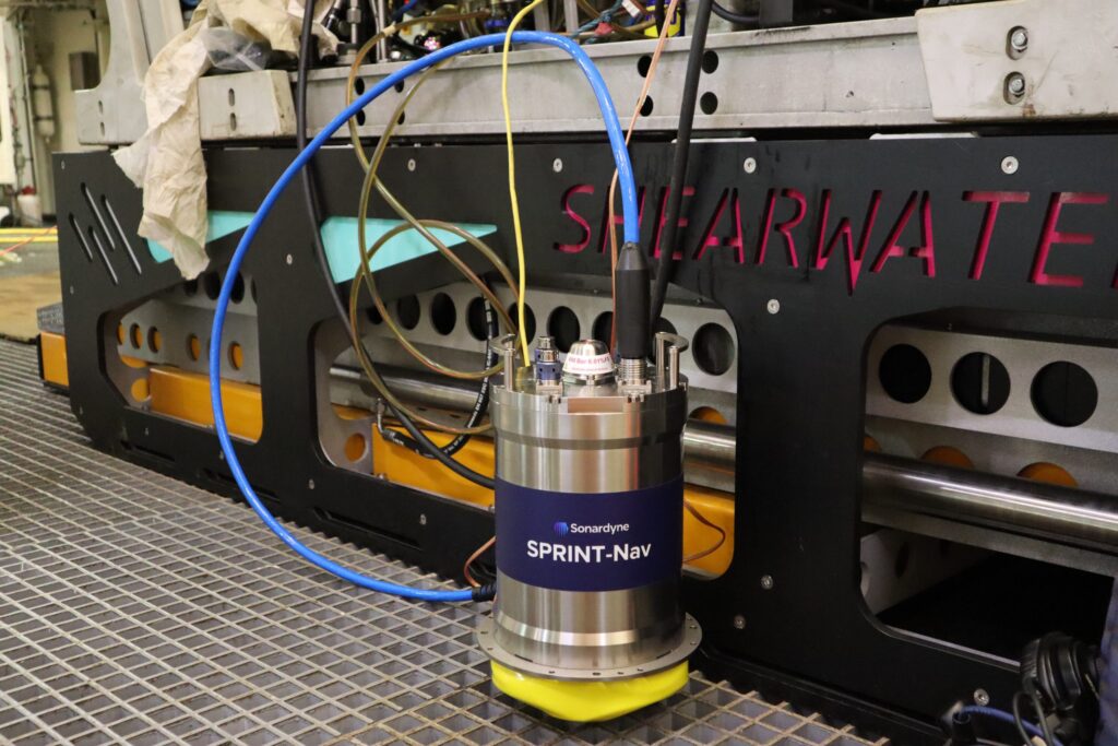
SPRINT-Nav combines INS (inertial navigation system), DVL (doppler velocity logger) and a pressure sensor into a compact, single housing, providing an all-in-one navigation instrument for underwater and surface vehicles. At Sonardyne, we combine our SPRINT INS and Syrinx DVL alongside a high accuracy pressure sensor, to create the SPRINT-Nav system.
How does a SPRINT-Nav work?
The IMU (inertial motion unit) measures the vehicle’s orientation and acceleration whilst the DVL measures the vehicle’s velocity relative to the seabed or water column and the pressure sensor measures the vehicle’s depth.
To provide accurate and reliable navigation information, SPRINT-Nav uses a tightly coupled algorithm to fuse the data from these three sensors. The algorithm considers the errors associated with each sensor to produce a navigation solution that is more accurate than any one of the individual sensors could provide on their own. Special calibration is not required to be performed before or during the mission to SPRINT-Nav being pre-calibrated. This is because the SPRINT-Nav simultaneously runs two algorithms: an attitude and heading reference system (AHRS) algorithm and an inertial navigation system (INS) algorithm. The INS algorithm can instantly initialise from the AHRS algorithm, allowing SPRINT-Nav to be used immediately after being turned on.
It is also fast to initialise, even if the vehicle is in motion; this is due to the use of ring laser gyros in the IMU which are very accurate and stable gyros and are not affected by dithering- a small, high frequency vibration that can introduce errors in gyros.
How can SPRINT-Nav be used?
SPRINT-Nav has a wide variety of applications, here are some examples. For an ROV, SPRINT-Nav can be used for piloting and navigation as well as dynamic positioning and mid-water station keeping with sparse LBL. For all subsea survey operations, SPIRNT-Nav 300, 500 and 700 offer a range of capabilities to suit your needs. In addition to this, SPRINT-Nav Mini is ideal for deploying on inspection class ROVs and small AUV platforms. SPRINT-Nav U (the world’s smallest hybrid navigator) is ideal for the missions where you don’t want to deploy a large vessel. For AUVs, SPRINT-Nav X achieves high navigational accuracy, which allows for long-endurance missions. For USVs, SPRINT-Nav can be deployed for control tasks in GNSS (global navigation satellite system) denied environments as well as aiding station keeping. SPRINT-Nav Mini can also be used as a dynamic positioning reference unit. Looking for SPRINT-Nav DP? Read our dedicated article to understand what SPRINT-Nav DP is and how you can use it.
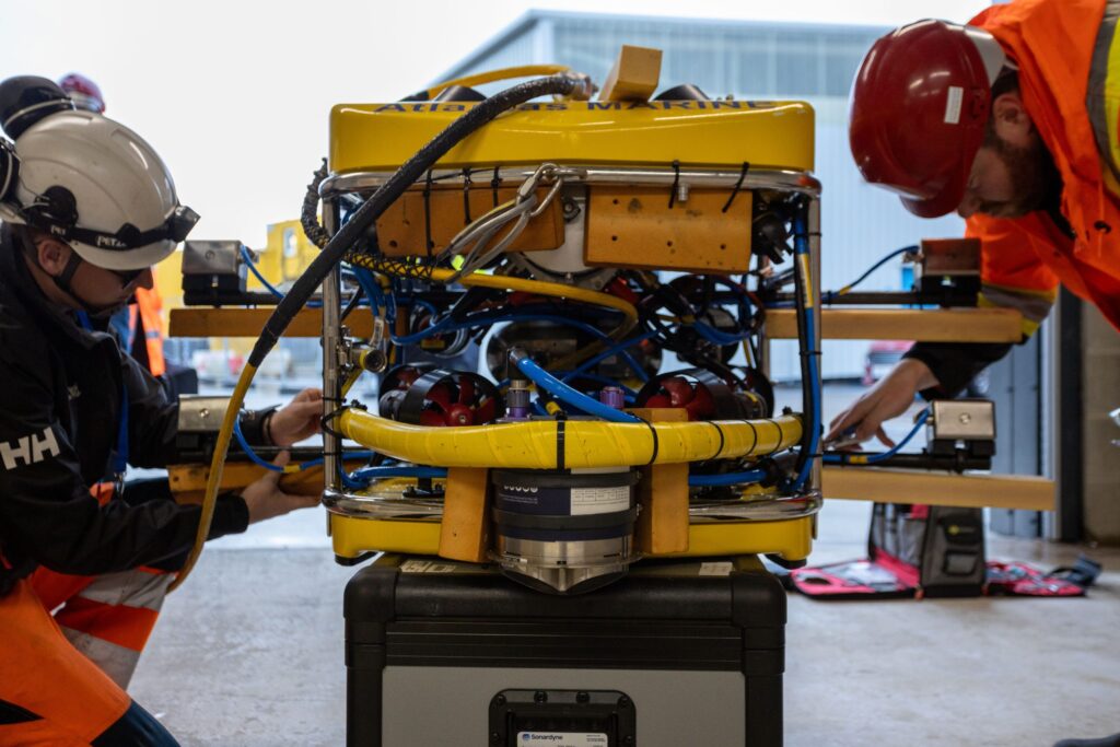
SPRINT-Nav installed on work class ROV
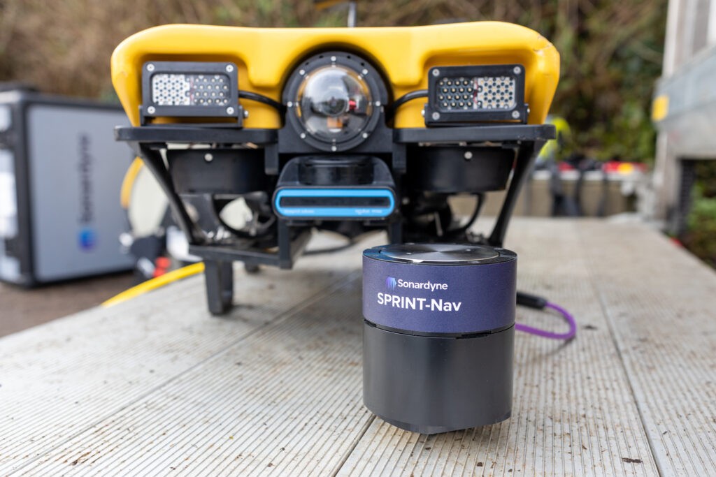
SPRINT-Nav Mini installed on an ROV
SPRINT-Nav U with an inspection class VideoRay ROV