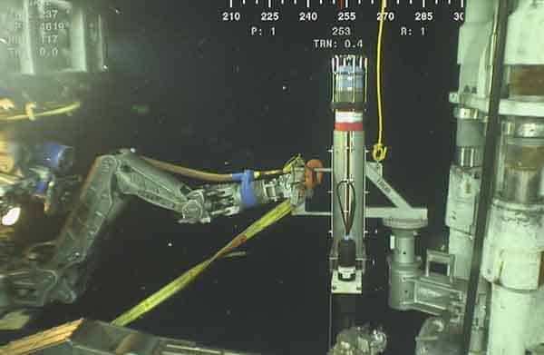
Underwater obstacle avoidance technology from maritime defence and security specialist Sonardyne International Ltd. has been chosen for a new design diver delivery unit (DDU) being built by SubSea Craft.
Sonardyne’s Vigilant forward looking sonar (FLS) will provide a critical hazard avoidance capability for the crew and embarked divers of the VICTA Class DDU when navigating on or below the surface.
Using a compact and sophisticated bow-mounted transducer arrangement, Vigilant FLS displays water depth, sub-surface obstacles and features by creating an accurate 3D model of the underwater environment over a 90° field of view. The model is displayed relative to the underwater vehicle or surface vessel it’s fitted to, overlaid on standard charts in real-time, providing operators with an easily-interpreted topographical image of their route ahead.
Vigilant FLS provides this detailed and easy to interpret 3D bathymetry out to 600 m, as well as automated warnings of unseen collision hazards out to 1.5 km, supporting safe navigation for mariners, underwater vehicle pilots and unmanned surface and subsea systems.
SubSea Craft’s VICTA Class DDU offers the speed and endurance of a long-range insertion craft with the stealth and capacity of a swimmer delivery vehicle. It can travel up to 250 nautical miles (nm) at speeds of up to 40 knots on the surface, whilst submerged it cruises at 6 knots, with a ‘sprint’ capability of 8 knots, for up to 25 nm to deploy and recover up to eight operatives (two crew and six divers) to their objective area mission-ready.
[blockquote author=” Tim Chicken, SubSea Craft’s Chief Commercial Officer”]”Being able to detect – at range – navigation hazards, before they become a real threat, is mission-critical to the sort of operations likely to feature in VICTA’s playbook. Vigilant is the solution. With Vigilant integrated into VICTA, complete with its easy to use, intuitive graphic user interface, pilots can visualise the environment ahead to navigate safely and avoid obstacles ensuring safe insertion and recovery of operators, regardless of the mission. As VICTA is designed around the operator, Vigilant was the ideal solution.”[/blockquote]
“Vigilant FLS offers naval forces with unprecedented subsurface situational awareness with unrivalled range,” says Ioseba Tena, Global Business Manager for Marine Robotics and Defence at Sonardyne. “With Vigilant integrated into VICTA, complete with its easy to use, intuitive graphic user interface, pilots can visualise the environment ahead to navigate safely and avoid obstacles ensuring safe insertion and recovery of operators, regardless of the mission. Quite simply, it provides a tactical advantage for their operations.”
Author: Stephen Auld, Global Business Manager, Subsea Asset Monitoring
As I’ve set out in the previous two blogs (Wireless Intelligence Made Easy and 21st Century Data Collection) in this three-part series, when you want to understand the fatigue life or integrity of your subsea systems you need two main elements. One is a way to accurately measure what’s actually happening, the second is a way to get that data from subsea to shore.
You also need a way to visualise the gathered information and understand what it all means. My previous two blogs focused on our SMART and AMT monitoring systems and different ways we can wirelessly access the data they gather for you, including using marine autonomous systems such as unmanned surface vessels (USVs) and autonomous underwater vehicles (AUVs).
For this third and final blog in the series, I’ll look at the final element you need; third-party analysts. Here’s where other companies, with their engineering and integrity experts, make use of the data our sensors gather to display, analyse, interpret and report to you on their findings. To put it another way, we measure, we monitor and we deliver data, either in raw or part analysed, summary form, to these trusted specialists.
Depending on what you want to know about your subsea system and how quickly, there are different routes you can take. Here are some options and examples of solutions we have provided to illustrate these various paths.
Challenge #1 – An operator was concerned about suspected and periodic vibration of a number of spool pieces within their deep water subsea field development.
- Solution #1 – the operator tasked their subsea inspection, repair and maintenance contractor with installing our monitoring technologies. This provided the data the operator’s external engineering consultancy needed to perform their fatigue analysis work to understand any impact on the spool pieces’ design life.
- Technology used – SMARTS and AMTs
- Data recovery method – Dunker 6 deployed from a production platform
Challenge #2 – An operator wanted real-time data so they could minimise fatigue on an aged wellhead caused by the blowout preventer (BOP) during a side-track drilling campaign.
- Solution #2 – they contracted a tethered-BOP system provider who contracted us to provide our monitoring technology. This enabled them, using third-party provided software, to view in near real-time any excessive BOP motion caused by drilling operations on the well, which could be stopped if the displayed fatigue exceeded a certain threshold.
- Technology used – SMARTS
- Data recovery method – Dunker 6 deployed from a drill rig
Challenge #3 – An operator wished to understand how much two flowline termination assemblies (FTA) were moving within their field development.
- Solution #3 – they used their subsea IRM contractor, who deployed our AMTs to measure movement of the FTAs. This resulted in the contractor designing a timely solution to inhibit the movement they had measured.
- Technology used – AMTs
- Data recovery method – seabed located SMART Dunker 6 hardwired through a control module
So, as I said, we measure, we monitor and we deliver data to your trusted specialists, whether that’s your in-house engineers, third party fatigue analysts or a specialist software provider. We provide them with the sensor information they need to perform their modelling and analysis. This in turn will inform the operator what they need to know about their subsea infrastructure.
Want to know more? Get in touch and we can provide robust sensors and through water, wireless, communication technologies to ensure the integrity and extend the fatigue life of your subsea assets.
Author: Stephen Auld, Global Business Manager, Subsea Asset Monitoring
In my last blog, the first in a three-part series, I looked at how our 6G enabled SMART and AMT acoustic hardware can provide the information you need to understand both high and low frequency movement of your subsea assets’ integrity and fatigue life.
These sensors provide seamless, wireless, monitoring for vibration and motion subsea as part of a stand-alone system, without any need for local power or communications umbilical.
So, once you’ve got your monitoring sensors in place, how do you access the information they’re generating? In short, there’s no single answer – that’s because there are now options to suit every scenario, including using marine autonomous systems (MAS).
Vessel or ROV deployed options
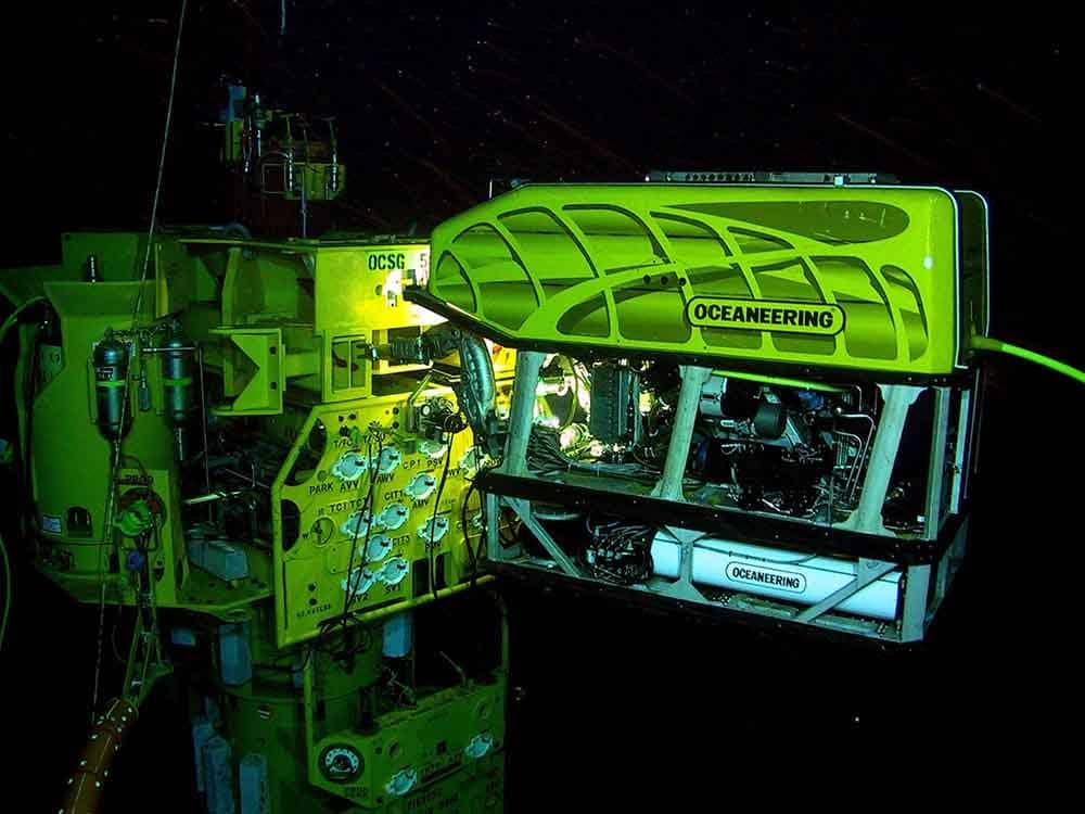
Conventionally, there are three main ways you’d get your sensor data: via a subsea transceiver connected into your control system; by a vessel with an over-the-side Dunker; or by using a remotely operated vehicle (ROV) with acoustic telemetry equipment. Let’s look at all three in a little more detail.
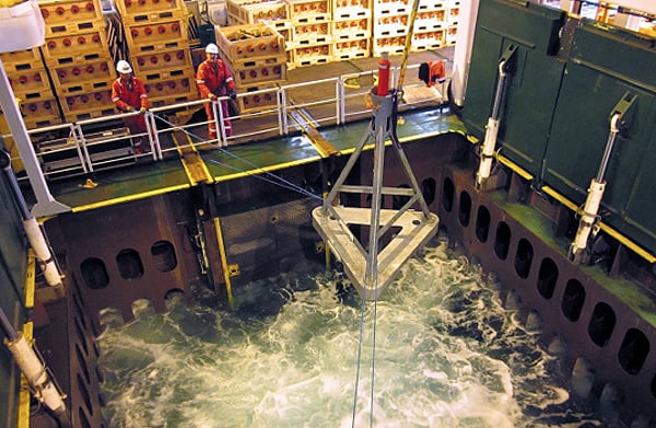
- With a hardwired system, you’d have a transceiver, such as our Dunker 6 or SMART-Dunker, mounted within a tripod on the seabed, connected to a subsea control module or other termination assembly. This subsea transceiver would gather the sensor data acoustically and then send it topside via the main umbilical. For monitoring systems that are spread over a large area, we can create an acoustic daisy chain to hop data to a central transceiver, which then delivers each sensor’s data via the one umbilical.
- For vessel-based data harvesting, if your ship already has Sonardyne 6G enabled transceivers on board, such as our Ranger 2 and Mini-Ranger 2 Ultra-Short BaseLine (USBL) systems, you can use them to acoustically upload the data from any of our sensors – because they all speak the same language. If you don’t have a transceiver on your vessel, you could rent or purchase a Dunker 6 transceiver, which could then be hung over the side of your ship, rig or platform and into the water, to acoustically retrieve your subsea sensor data.
- If you have a ROVNav 6+ fitted on your ROV, you have everything you need to harvest data from our 6G SMART and AMT monitoring instruments. The ROVNav 6+ on the ROV just needs to be within acoustic range to gather the data which it then sends topside via the ROV’s umbilical.
These are the conventional methods we’re all used to. But there are now alternatives. Increasingly, we’re using new ways of harvesting data remotely and wirelessly, at far lower costs and with vastly lower carbon emissions, using unmanned surface and subsea systems.
Data harvesting with unmanned surface vessels (USVs)
First, let’s look at unmanned surface vessels (USVs), sometimes called surface gateways – as they provide a relay, or gateway, for your data. The number of USVs on the market has exploded in just a few years and we’re increasingly able to use them for data gathering operations.
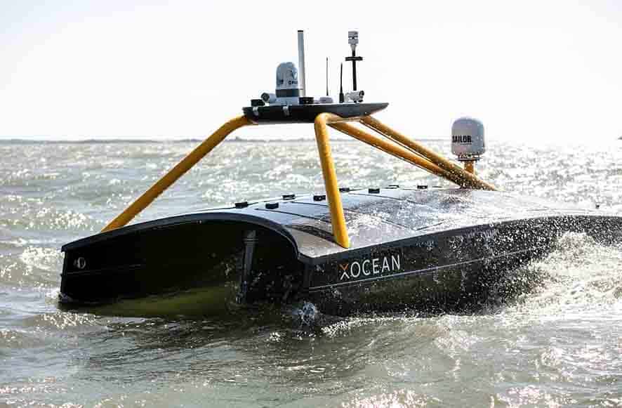
We’ve already been working with a wide range of providers, including L3 Harris ASV, XOCEAN and Maritime Robotics, using a number of different platforms, including Wave Gliders, to head offshore and gather data. Read about work we’ve done with each of these by clicking the links on their names.
The benefits of installing our systems on USVs for data harvesting include a vastly reduced carbon footprint, enabling staff to work remotely, which is crucial in the current Covid-19 environment, as well as reducing costs, making more frequent harvesting missions eminently viable. But there are also operational benefits. For example, we’ve been able to enter the 500 m exclusion zone in order to harvest data, because these systems, being so much smaller than any manned vessel, pose minimal threat to production systems.
Their efficiency is also enhanced thanks to low hull and propulsion noise, so data can be harvested faster than from a noisy manned vessel. Just like a manned vessel, they can also beam the data they gather to shore via Iridium satellite or 4G, depending on local communications availability.
Your data collection options
To make any USV “data-harvest-ready” with our systems is quite simple. Depending on the size of the USV and how much you want it to do, we have a number of options:
- Modem 6 – our acoustic modem family
- Dunker 6 – our LBL and telemetry transceiver for deployment from vessels or USVs
- Or one of our Ranger USBL family of High Performance Transceivers (HPT), depending on the water depth you’re working in and the precision that you want.
- If you’re also doing positioning, you may want our Gyro USBL – removes calibration requirements so great for using on dynamic vessels of opportunity.
- Acoustic Communications Module – ideal for gliders, all the electronics you need, housed in a compact form factor, with a remote transducer
- Wave Glider Transceiver (WGT) – all the electronics you need, including a satellite link, with a remote transducer
Each of these systems can interface in several different ways with the vehicle’s management system for access to the previously recovered data. When instructed to do so, the unmanned vehicle can then transmit the recovered data via Iridium or for example a 4G cellular network back to shore.
Get in touch if you want to learn more about this amazing technology.
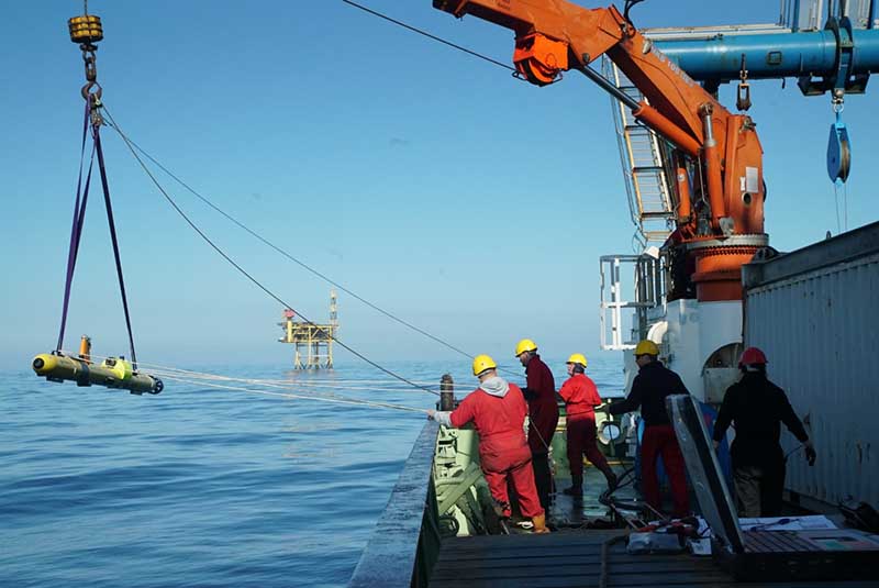
Letting the underwater drones do the work
Another option is to use underwater drones, or autonomous/unmanned underwater vehicles (AUV/UUV) for your data gathering missions. In fact, your AUV/UUV may already be equipped for data collection, if it has an AvTrak 6 or AvTrak 6 OEM Nano telemetry transceiver on board.
- AvTrak 6 OEM – our vehicle-ready, self-contained vehicle tracking and communications transponder
- AvTrak 6 – as above, but within our subsea housing
Once the data has been harvested, your AUV can either transit to a wired subsea transceiver or meet up with a USV, to offload its data. Of course, it could also be recovered by a conventional vessel using a Sonardyne transceiver or by downloading the data once the AUV has been recovered on the back deck.
If there’s a substantial amount of data to be retrieved, our BlueComm free space optical modem enables multiple megabytes of it to be offloaded, quickly. This is perhaps more relevant in seismic data acquisition operations, but could also be useful when monitoring requires a high level of data transfer, for example, downloading raw or time series subsea asset motion data.
Just as you can with an AvTrak, with an integrated BlueComm your vehicle can gather data then offload it either to a BlueComm hardwired into the subsea infrastructure to then send down the umbilical or to a manned or unmanned surface vessel, with a corresponding BlueComm receiver. To put it another way, we no longer have a problem handling high bandwidth data subsea!
Conclusion
So, what’s the upshot of all of this? In a nutshell, when you’re monitoring subsea assets using our equipment there are numerous ways, both conventionally and now also using MAS, such as USVs and AUVs, to access as much data as you would like wirelessly. And this isn’t just for subsea asset monitoring, it can be for data collection from any type of subsea sensor.
In my next blog, I’ll take you through what happens now you have your data and who helps you to understand what’s happening in your subsea system.
We can help and assist on all aspects of data harvesting missions, including organising the most appropriate and efficient data gathering platform for the task. Get in touch to find out how we can help you.
Author: Stephen Auld, Global Business Manager, Subsea Asset Monitoring
Part 2
Part 3
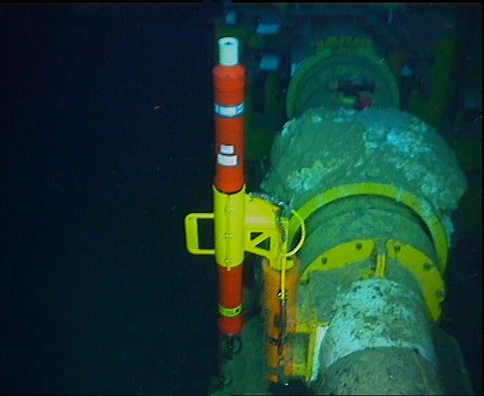
Globally, the installed base of subsea production pipelines and flowlines continues to grow. As well as increasing in number they’re being installed in harder to reach places, in deeper waters, in harsher conditions and with more challenging fluids and gases passing through them.
Whether they’re new or existing subsea assets, understanding the impact of fatigue caused by both high and low frequency vibration is high on operators’ wish lists. At Sonardyne, this is a challenge we’re hearing more and more about from our customers. Integrity monitoring and management of these systems, through the life-cycle, is an increasingly important requirement.
Using traditional methods, i.e. remotely operated vehicles (ROVs) from a manned support vessel, to visually inspect what is happening, is costly, which means it’s often done infrequently, resulting in patchy information. This is especially so for more complex infield pipeline infrastructure, like spool pieces, and is problematic when an operator wants regular or even real-time data.
So, in a cash-constrained environment, how can operators keep on top of their pipeline system integrity while keeping their spending in check? How about an easy to retrofit system that doesn’t impact on your production system and doesn’t need local power or communications links? One trip – and it’s installed. Then you have all the data you need.
Wireless intelligence on the seafloor
That’s just what we can provide. We have a track record in developing and deploying highly configurable remote and wireless subsea asset monitoring systems, enabling operators to monitor pipelines for integrity issues, including pipeline lateral buckling, walking or creeping, caused by axial stress in the pipe and high frequency vibration.
Based on our 6G hardware backbone, our low and high-frequency movement monitoring technologies are easy to configure for any subsea layout or scenario. For example, our Subsea Monitoring, Analysis and Reporting Technology (SMART) sensors are ideal for high-frequency vibration monitoring, while our Autonomous Monitoring Transponders (AMTs) are perfect for more low-frequency movement monitoring. They can also easily be used together.

They’ll measure, record and even part-process the data at source where it can either be stored or transmitted using our Wideband digital through-water communications to the surface – which could be to a topside vessel, platform, rig or unmanned vehicle. That’s all without the need to tap into existing power or communication systems and with no impact on the pipeline system, because all our subsea sensors are battery-powered – some with greater than 10 year battery life. Alternatively, where access to a hardwired umbilical is available, the remote monitoring data can also be via a subsea transceiver then on to the topside using that existing umbilical link.
Once topside, the data can be sent via a cable link, satellite or 4G offshore network to shore, where analysts can help you refine your pipeline management strategies.
It’s SMART
SMART is an all-in-one, easy to deploy, low-power, long-duration, subsea data logging and processing and acoustic telemetry instrument. SMART can interface with a wide range of internal and external sensors and other data sources. It’s often used for recording and processing high-frequency six degrees of freedom movement, often caused by vortex-induced or flow-induced vibrations.
With in-built edge computing capabilities, SMARTs can use either standard or customer bespoke data analysis algorithms to provide small statistical summary data packets. These packets can be acoustically transmitted robustly and efficiently through the water to a topside transceiver. It’s a highly flexible instrument, ideal for those trouble spots where you suspect high-frequency vibration could lead to issues further down the line.
AMT for low-frequency monitoring
However, what about low-frequency, long-period subsea asset movement? That’s where our AMT long-endurance transponder can help. It can autonomously acquire and log acoustic ranges and other sensor data, like temperature and pressure. By deploying a fixed seafloor LBL array of AMTs so that each can make highly accurate range measurements to “mobile” AMTs mounted on a pipeline, for example, they can tell an operator whether, and by how much, their pipeline is moving over time.
Each AMT also has a highly accurate pressure and sound velocity sensor, so that vertical movement of the pipeline, as well as horizontal movement, can be observed. Inclinometers integrated into the AMT can be added as an optional extra to detect any changes to the pitch and roll of the pipe or other subsea asset. It’s ideal for those slower movements, like creeping or buckling, that are hard to detect during periodic ROV inspection campaigns.
Hybrid solutions for all subsea monitoring scenarios
What’s more, we can combine the two, to provide a SMART-AMT. This is a hybrid solution that’s able to capture high and low-frequency movements. It’s perfect for monitoring free-spans or production risers, without having to perform regular visits with your ROV, vessel and crew.
I’ll be covering, in more depth, different ways you can retrieve your data, including using marine autonomous systems, in my next blog.
For all of your projects, we are able to provide full customer support, including project management, array planning, data processing, field support and post-processing software development, enabling the most efficient project outcome for your entire subsea asset monitoring data requirements.
Get in touch if you’d like to find out how we can help you.
Brazilian geoscience services company OceanPact Geociências has chosen deep water positioning technology from Sonardyne Brasil Ltda. to support its geophysical, geotechnical and environmental research operations across the region.
Ranger 2 Ultra-Short Baseline (USBL) systems have been installed on board OceanPact’s research vessel Seward Johnson and RSV Austral Abrolhos to precisely track the location of underwater equipment and sensor packages deployed from the ships, including seabed corers, towed sensors and data loggers. Both vessels are currently on hire to Brazilian oil major Petrobras.
Ranger 2 USBL is a popular choice for conducting research at sea as operations can start as soon as a vessel arrives on location. This helps maximise valuable ship time. It has the capability to track multiple underwater targets simultaneously to beyond 11km, works in shallow or deep water and is able to remotely configure and communicate with compatible instruments. This operational flexibility was a key factor in OceanPact’s investment decision.
[blockquote author=” Raphael Melo, Survey Manager from OceanPact Geo”]”For geophysical, geotechnical and environmental research and survey operations in Brazil we rely on the highest specification and highest reliability systems. Sonardyne’s equipment has proven to be both during our previous long-term rentals. This is why we have chosen now to permanently acquire this equipment for two of our vessels. Having the reassurance of local technical and operational support from the Sonardyne team here in Brazil is a big advantage for us also.”[/blockquote]
Andre Moura, Sales & Applications Manager at Sonardyne Brasil Ltda. says, “This order from OceanPact further embeds Ranger 2’s reputation in the region. For those wanting accuracy and versatility, it’s proven itself time and again while also meeting the toughest specifications from oil and gas, science and survey companies.”
In his second blog on measuring the restless earth, Geraint West, Global Business Manager for Ocean Science, explained how Sonardyne technology is being used to measure underwater landslides down the sides of Mount Etna. In this, his third blog, in a three-part series, he explains how an emerging technique called GPS-Acoustic (GPS-A) is having a major impact on the way scientists understand subduction zones, which could in turn increase the possibilities of being able to predict tsunamis and earthquakes.
Plate tectonic motion measurement
While direct ranging produces detailed relative measurements, measuring the movement of a submerged oceanic tectonic plate that is colliding with a continental plate requires absolute positioning within a world reference frame. While the techniques for doing this on land are quite mature, complementary underwater observations rely on an emerging technique called GPS-Acoustic (GPS-A).
GPS-A combines GPS and acoustic measurements. Firstly, the acoustic transducer on a surface platform is positioned with highly accurate kinematic GPS and an attitude sensor. Secondly, simultaneous acoustic ranging from the surface transducer positions a seabed transponder. By undertaking averaged observations over several days, it’s possible to achieve world geodetic frame positioning to centimetre-level. Repeating these observations once or twice a year yields absolute measurement of change in seabed position.
The GPS-A technique was first developed by Scripps Institution of Oceanography in the 1980s, with the first site established offshore Vancouver Island in the mid-1990s. However, these early GPS-A stations were costly to establish as they were dependent on using a ship or buoy as the surface platform. Since 2013, Sonardyne has provided commercial off-the-shelf technology to underpin Scripps’ GPS-A work, including development of a modular payload for Liquid Robotics’ Wave Glider unmanned surface vessel (USV), which has now provided the capability to perform these observations much more economically.
GPS-A is the basis for the new North Cascadia Subduction Zone Observatory (NCZSO), which will comprise seven GPS-A sites deployed in 400-3,000 m water depth offshore Vancouver Island, each comprising three Sonardyne Fetch instruments. An additional three units, equipped Sonardyne’s new in-situ pressure sensor calibration system known as Ambient Zero Ambient (AZA), are also being connected to Ocean Networks Canada’s (ONC) cabled NEPTUNE array. NEPTUNE is an 800 km-long loop that covers the coastal zone, the northern part of the Cascadia Subduction Zone (CSZ), Cascadia Basin and the Endeavour Segment of the Juan de Fuca (JdF) Ridge with a network of seismometers and bottom pressure recorders (BPR).
The problem is that, in comparison with many other subduction zones, NEPTUNE’s seismometers are observing relatively low levels of small earthquake activity, which are normally used as indicators of future larger events, resulting in many questions about what is happening at the CSZ. Establishment of the NCSZO GPS-A stations has therefore become critical to resolving the ambiguity between two separate models that have been developed for Cascadia. In one, the JdF oceanic plate is subducted very slowly beneath the North American continental plate, releasing strain as it creeps along with minimal seismic activity. In the other, the two are locked together, causing a dangerous build-up of strain, which could ultimately be released in what Pacific Northwesters refer to as the “Big One.” Led by the University of Victoria’s ONC initiative and including the Pacific Geoscience Centre and Scripps Institution of Oceanography, the aim of the NCSZO is to use GPS-A to reveal which parts of the CSZ are creeping and which are locked.
Lying just 50 km offshore, the CSZ poses the very real threat of both earthquakes and tsunamis to a series of major cities on the Pacific North-West region of America, ranging from Portland, in the south, to Vancouver, in the north. Scientists therefore have high expectations of the NCSZO, which will be deployed during 2019, for an initial planned duration of seven years. In ONC Senior Staff Scientist, Science Services Martin Heesemann’s words, “data provided by the NCSZO are certain to enable major breakthroughs in the scientific assessment of earthquake and tsunami risks related to the CSZ.”
Sustained presence in dynamic environments
The emergence of technology capable of investigating such varied processes on the seabed is timely. Previously, studies have been limited to capturing just snapshots of the processes at work, often with spatial and/or temporal constraints, which have led to incomplete, flawed or ambiguous conclusions.
These new capabilities are therefore heralding a new era of sustained seabed observation with the ability to measure events at high resolution in both space and time, over decadal timescales. Exploitation of these capabilities is still in a nascent stage, but, as we have seen across these three blogs, focusing on the monitoring of our restless earth, underwater, the synergy between earth scientists and Sonardyne is strong and likely to help develop further future capabilities.
Read the first blog here.
Read the second blog here.
Marine robotics company, Sonardyne International Ltd. has demonstrated technologies that will aid autonomous vehicle operations in challenging environments under a project funded by the UK’s national Defence and Security Accelerator (DASA).
Working with a 12 m-long SEA-KIT X class unmanned surface vehicle (USV), Sonardyne tested and validated sensors already used by unmanned underwater vehicles for use on USVs in support of missions in coastal waters
Specifically, Sonardyne’s market leading SPRINT-Nav hybrid inertial navigation instrument was integrated into a SEA-KIT X and tested against local real-time kinematic (RTK) GPS positioning, as part of the DASA programme to fast-track autonomous vehicle capability in challenging or harsh conditions.
Loss of satellite-based timing signals needed for navigation and positioning can occur in ports and harbours around tall structures or close to cliffs or inside fjords, where GPS or GNSS receivers may not have a clear line of sight with the sky. It can also happen through deliberate signal jamming or degrading of performance, known as spoofing.
Sonardyne’s SPRINT-Nav is already proven as a reliable navigation instrument for unmanned underwater vehicles, which operate in what is effectively a GPS or GNSS denied environment. Now it will also be used to provide a high integrity, continuously available navigation solution for a USV, like SEA-KIT X, operating in littoral zones in water depths up to 150 m.
SEA-KIT is a 10,000 nautical mile-range vessel able to carry up to 2.5 tonnes of payload and deploy and recover autonomous underwater vehicles (AUVs) and remotely operated vehicles (ROVs). This capability, and flexibility, means it is well suited to support naval missions including intelligence gathering, hydrographic survey and as a communications gateway.
Ioseba Tena, Global Business Manager, Defence and Marine Robotics at Sonardyne, says, “Most USVs rely on uninterrupted GPS or GNSS signal updates to inform their situational awareness and plot a course safely. When there’s no signal, or what’s called spoofing or jamming, USVs must consider alternative navigation sensors and instruments or they need to be remotely piloted adding expense and risk to over-the-horizon operations.
“By integrating SPRINT-Nav onto a USV, such as SEA-KIT, we have shown we can overcome this challenge, providing a continuous and resilient navigation in denied environments capability that will be ideally suited to challenging operations such as mine-counter measures (MCM).”
In total, 21 contracts were awarded by DASA, on behalf of the UK’s Defence Science and Technology Laboratory (Dstl), amounting to £2.1 million in funding. The awards are part of the Autonomy in a Dynamic World competition, launched last year, which aims to address factors that affect the military effectiveness of current autonomous technologies.
[blockquote author=” Helen Mullender, DASA project manager”]”The work being funded is to mature autonomous systems with the capability to operate on demand, under all conditions that may be encountered. Military operations are undertaken in all kinds of challenging environment. The inclusion of autonomous systems in these operations will demand their ability to operate effectively and efficiently regardless of the environment.”[/blockquote]
The competition is funded through the MOD’s Chief Scientific Adviser’s Research Programme’s Autonomy Incubator project that aims to: Identify and develop underpinning research and technologies to support the development and fielding of unmanned systems across defence which may be matured through the Dstl Autonomy Programme and other Research and Development programmes.
Dstl delivers high-impact science and technology for the UK’s defence, security and prosperity. Dstl is an Executive Agency of the MOD with around 4,000 staff working across four sites; Porton Down, near Salisbury, Portsdown West, near Portsmouth, Fort Halstead, near Sevenoaks, and Alverstoke, near Gosport.
To do real-time SLAM, a new set of algorithms was developed using raw ranges from Compatt 6+ transponders in the SPRINT INS, which is in turn managed by Fusion 2, all in real-time. All you need is a ROVNav 6+ on your ROV, a SPRINT-Nav (or SPRINT INS and a DVL), and one Compatt 6+ transponder at a known or boxed-in location.
Starting at your known location, you then pilot your ROV on a SLAM trajectory, while ranging to the known location and to the Compatts required to be calibrated, to perform SLAM calibrations on each Compatt 6+ in turn – a routine that can be performed concurrently to your pre-lay survey. We have a white paper on what we have learned with regards how to perform SLAM calibrations which is available for people to use for working into their procedures. Just ask us if you’d like to see it.
In a brownfield location, where there are already known positions, and you are, for example, laying a new pipeline for a tie-back project into an existing asset, the SLAM process can be further optimised; put a Compatt at that known location and you’re ready to SLAM straight away, potentially no box-ins required.
Intuitive interface
In Fusion 2, the real-time status of the calibration is displayed intuitively and as soon as the SLAM calibration meets your accuracy criteria the calibration can be finished, and you are straight into tracking. There are no delays due to post processing.
This is still just the start of the journey. We continue to evaluate the scope there is to re-think and simplify survey tasks by taking advantage of SPRINT INS-aided operations in Fusion 2.
We’ve been improving structure positioning by including acoustic heading into the tracking. We’ve also now released a wireless structure deflection monitoring module that can be run in Fusion 2 and we already have Fast-LBL, enabling up to two-second update rates of structures being tracking in full LBL arrays with sensor data – depth, sound velocity, pitch, roll and heading – being streamed wirelessly at the same time.
Rethinking your operations
By looking at your operation differently, you can also do more. For example, at the moment, you cannot track a mobile Compatt on a structure within a sparse array, as you haven’t got a SPRINT INS on it. But, instead you can dock an ROV with our SPRINT INS* onboard onto a structure whilst you track that in sparse LBL mode during installation. Or why not track an ROV in sparse LBL mode, install sand bags as visual markers to mark the structure landing area, and, knowing the markers are installed correctly, position the structure visually?
It’s going back to basics but it works. As Mike Clark mentions in our blog here, a lot of how we operate is restricted due to operator specifications. They say we must have a positioning transponder on the structure to land it, but why?
Remote training for Fusion 2
Want to learn more? If you’re trained in Fusion 1, all you need is a one day top up course to be able to be up and running with Fusion 2. We’re now offering these remotely, on a one-to-one basis, so you can complete the training where ever you are in the world, at home or offshore.
We’ll cover the theory, go through demonstrations and then give you remote access to the software to try it for yourself and run through a host of scenarios to make sure you’re comfortable with your new skills.
Contact our Training Team at [email protected] for more details or watch our video on real-time SLAM calibration here:
*It will also work when your ROV has our SPRINT-Nav 300, 500 or 700 onboard.
Underwater positioning specialist Sonardyne International Ltd. has increased the capabilities of its Fusion 2 software package to enable surveyors and construction personnel to do even more, both on and offshore, with their existing hardware.
This latest release of Fusion 2 unlocks new benefits, including a simplified surface box-in app and the ability to perform wireless structure deflection monitoring, without having to deploy specialist hardware. Additionally, Fusion 2 now includes ‘office’ mode as standard, allowing project teams to plan and fine tune procedures before doing them for real offshore. Multi-user mode now comes as standard when using Sonardyne’s Compatt 6+ transponder arrays, bringing the savings of simultaneous operations to all users.
Until now, structure deflection monitoring (SDM) – a requirement for most construction campaigns – usually meant having to buy or rent dedicated systems that require lots of cabling. Now, with the Fusion 2 SDM rentable add-on module, subsea construction staff can install their existing Compatt 6+s on each corner of a structure that is to be installed, and a Gyro Compatt 6+ and, supported by their existing ROVNav 6+ remotely operated vehicle (ROV) transceiver, launch straight into wireless structure deflection monitoring. This new capability reduces interfaces, costs and complexity, making operations simpler and faster.
With the new complimentary office mode, users can do more from onshore, including planning for LBL and INS offshore campaigns and running tests such as geodetic checks, through to post-processing of LBL calibrations, reducing offshore workload and risk. The new box-in app makes interfacing with third-party USBL systems, such as HiPAP, for range only box-in operations far simpler and easier – and again is enabled as standard.
With just a single cable connection from the vessel’s USBL system to Fusion 2, operators will be able to run seamless real-time box-in operations. What’s more, Compatt 6+ multi-user functionality is now free to access through every Fusion 2 system, enabling up to five different users at any one time for operations from box-in to ROV tracking, all via a simple Compatt selection interface.
[blockquote author=” Edward Moller, Global Business Manager – Construction Survey, at Sonardyne”]”With each update to Fusion 2, we’re adding new capabilities and increasing the ease and simplification of what are in fact complex survey and construction operations. In the past, for many operations, different systems need to be interfaced, which made operations inefficient, and specific hardware was needed for certain operations. Now, it comes in one package that works with the hardware operators already have in their inventories.[/blockquote]
Fusion 2 Version 2.02 will begin shipping from May 19 and is available as a free of charge remote infield upgrade to existing owners of a Fusion 2 license. Users are advised to email their request to: [email protected]. Pricing details of the SDM add-on module is available by contacting your local sales office.
In his first blog on monitoring the restless earth, Geraint West, Global Business Manager for Ocean Science, explained how scientists are able to measure underwater ‘avalanches’, or oceanic turbidity currents using our Autonomous Monitoring Transponders (AMTs). In this second blog, of a three-part series, he explains how the same versatile instruments are being used to measure underwater landslides down the sides of Mount Etna, an active stratovolcano on the east coast of Sicily, Italy.
GEOMar Mt. EtnaI’ve previously outlined, the deployment of an AMT network by the GEOMAR Helmholtz Centre for Ocean Research in Kiel to monitor deformation on the Nazca-South American plate boundary using direct ranging measurements with AMTs. Derived from Long BaseLine (LBL) acoustic positioning techniques, this involves acoustically measuring the change over time of the relative horizontal displacement between pairs of transponders, while integrated high-resolution pressure sensors measure the change in their relative vertical displacement.
This technique results in millimetric measurement of relative movement between transponders at a high temporal resolution, providing detailed information about seabed deformation over a local area.
Using this technique, GEOMAR measured underwater slippage of the southeast flank of Europe’s most active volcano, Mount Etna, for the first time between April 2016 – July 2017. Satellite observations have previously shown that the flank of the volcano is slowly sliding towards the sea. But, until a network of AMTs was deployed beneath the waves, it was impossible to confirm if and how the submerged segment was moving.
Fetch Scenario 2The GEOMAR array comprised a network of five AMTs placed astride of the fault in about 1,200m water depth. Three were on the presumed unstable flank and two on the adjacent stable slope. Measurements logged during a 15-month period confirmed that the entire flank of the volcano is in gravity-driven motion. In one event, the slope slipped about 4 cm in just eight days. The consequences are potentially dramatic.
“The entire slope is in motion due to gravity. It is therefore quite possible that it could collapse catastrophically, which could trigger a tsunami in the entire Mediterranean,” explains Prof. Heidrun Kopp, co-author of a paper on this project.
While there is still more work to be done towards fully understanding the processes at work on coastal volcano flanks, Dr. Morelia Urlaub, another study co-author, is excited about the potential to greatly improve understanding of these processes; “Our investigation shows that the sound-based geodetic monitoring network can be a tremendous help in this respect.”
Read the first blog here.