Since we launched SPRINT-Nav in 2015, the benefits of not just bolting together, but tightly coupling an inertial navigation system (INS) and Doppler velocity log (DVL), with a pressure sensor, have been clearly demonstrated. The result is a pre-calibrated and easy to install instrument (no more offset calculations!) with greater capabilities than the sum of its parts.
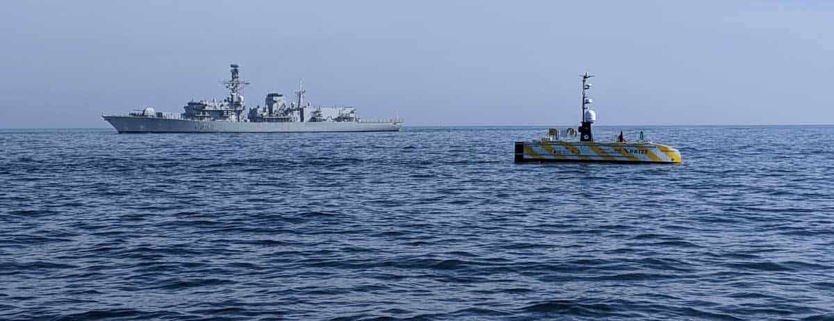
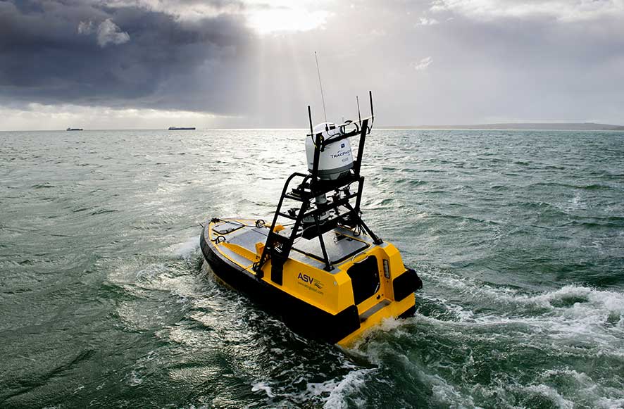
The benefits are obvious. The result is that SPRINT-Nav has become a navigation instrument of choice for many underwater vehicle platforms around the globe. Not only that, it’s also now supporting uncrewed surface vessel (USV) navigation. While SPRINT-Nav was designed for underwater vehicle navigation (because they can’t access GNSS signals), it’s also able to provide the same data – tightly integrated INS and bottom track – as an additional navigation source to USVs to ensure they always know where they are. This is especially useful for USVs working in areas where GNSS signal could be compromised and for surveys needing the highest accuracy. This is possible because SPRINT-Nav contains our Syrinx DVL. Beam level data from Syrinx is used by SPRINT within the instrument as it continuously computes its position.
Adding acoustic Doppler current profiling (ADCP) to the mix
But why stop there? We’ve now also introduced acoustic Doppler current profiler (ADCP) capability to SPRINT-Nav and we’ve extended the altitude at which both the DVL and ADCP can work. That means that underwater vehicles and USVs now have a greater operational envelope for navigation and can also measure water currents – at the same time.
SPRINT‑Nav can continue to use bottom‑tracking data from the Syrinx to compute its position, exactly as before. The bottom‑tracking acoustics, which rely on signals bouncing off the seafloor, can now be alternated with ADCP signals, which bounce off particles in the water. The ADCP returns are known as backscatter, and by measuring these we can figure out the water speed at different depths beneath the SPRINT-Nav – the current profile. What’s more, because the SPRINT-Nav also contains an INS, it’s able to compensate the ADCP data for vessel motion, even if you do not have bottom lock from the DVL.
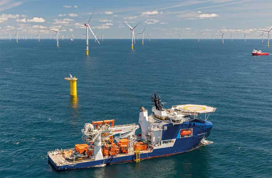
ADCP data has multiple applications. The water velocity data can be kept and used to monitor, for example, current regimes for tidal energy projects, deep ocean currents, or currents around wind farms, to predict or monitor scouring. Since SPRINT‑Nav is vessel‑mounted, the instrument can be deployed to locations where ADCP data is needed, instead of relying on static seabed or buoy mounted ADCPs. However you are using your SPRINT-Nav ADCP, its PD0 data is logged and can also be streamed to another application.
Taking tracking and ADCP profiling to a higher level
Our standard 600 kHz Syrinx DVL can bottom track down to 175 m and the ADCP works down to 80 m. Integrated into SPRINT-Nav, the same performance applies. We recognised that many USVs might want to track deeper waters than this, so we’ve extended the range with a 400 kHz DVL with ADCP capability. That takes the DVL range to more than 200 m and the ADCP to 120 m. Integrate that into SPRINT-Nav and you have our new high altitude SPRINT-Nav variant. Late last year, we took this instrument for a spin in some Scottish waters known for a wide range of tidal and current environments, including tidal falls and whirlpools. We’re really pleased with the results, from being able to see marine mammals and their wakes to eddies created by waterflow as well as haloclines in the data.
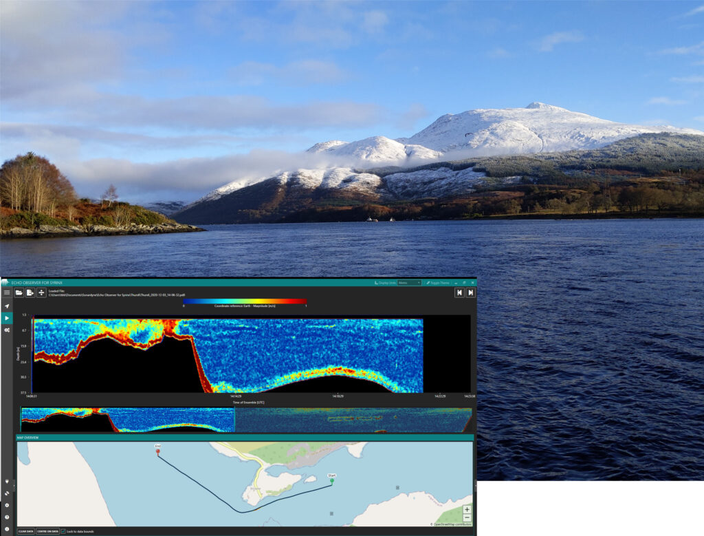
We toured a number of locations around Connel Bridge, the Firth of Lorn, Sound of Mull and into Loch Etive, where we had the stunning backdrop of Ben Cruachan – as you can see above.
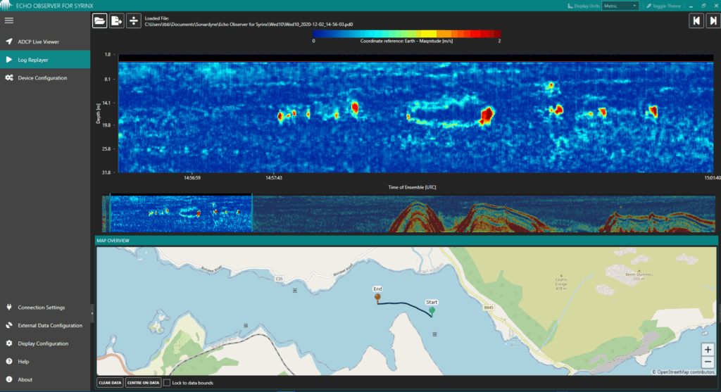
We transited through deep water (~210 m) and high tidal flow rates (~5 knts), undertook transects across rivers, through fresh-salt water boundaries and went through calm protected waters with an abundant of marine life. Throughout, a wide range of water velocity components were measured and visualised in real-time waterfall plots using our Echo Observer software. You can see an example of a waterfall plot above and we’ll show you more below.
Dedicated ADCP software
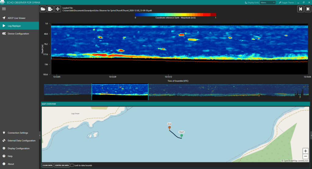
Our ADCP software, Echo Observer, lets users flick easily between different waterfall plots of the different velocity components, i.e. north, east and upwards, as well as velocity magnitude. The real-time plot, higher resolution snippets can also be shown simultaneously, if users want to focus on a particular element of the plot. It offers great spatial awareness – you can see what locations you’ve already visited and how they relate to the where you are currently. You can zoom in (the main viewing window), track back in the data (the plot below) and see the features and landforms you’re going past (the navigation chart), as shown in the image above and that you will see in our other screen shots below. This visualisation is possible in real-time, where the more detailed snippet is the most recent set of data, or later when you’re inspecting the data and you want to view a specific snippet.
Integrated INS compensation for ADCP data
Imagine you are capturing ADCP profiles from a moving vessel in deep water. You can’t bottom track due to the high altitude above the seabed, so how do you account for the vessel speed in your ADCP data? Can the INS in SPRINT-Nav provide vessel velocity estimates in place of bottom track velocities? We tried this out by turning off bottom‑tracking in SPRINT‑Nav and did transects over 120 m of water, but only profiled the first 100 m.
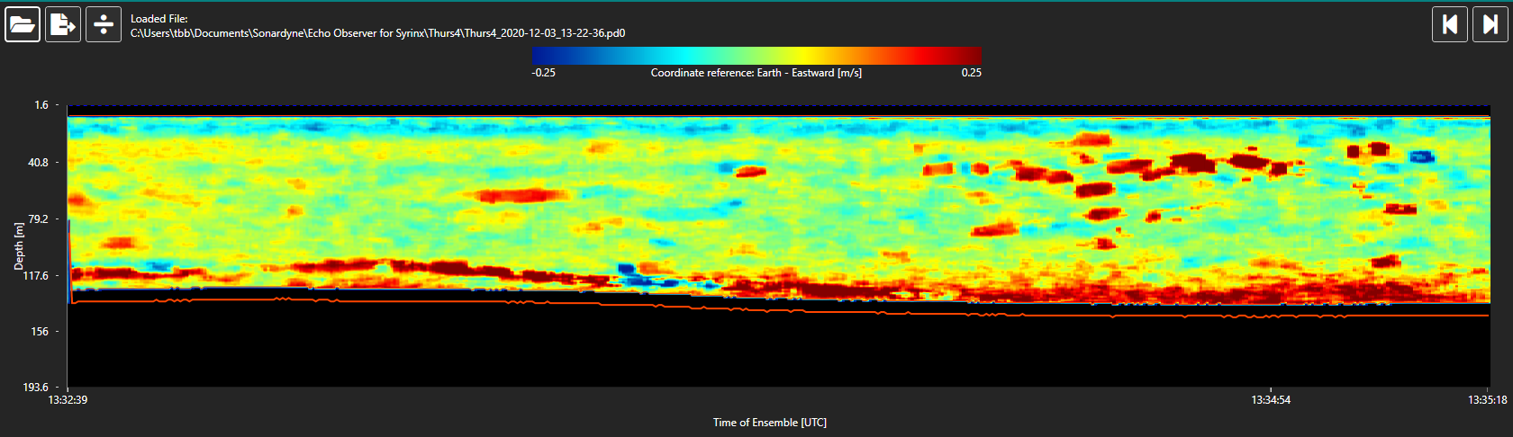
The waterfall plots in both images below, taken from Echo Observer, show eastwards velocity, with the Y-axis representing depth increasing from top to bottom, the X axis is time.
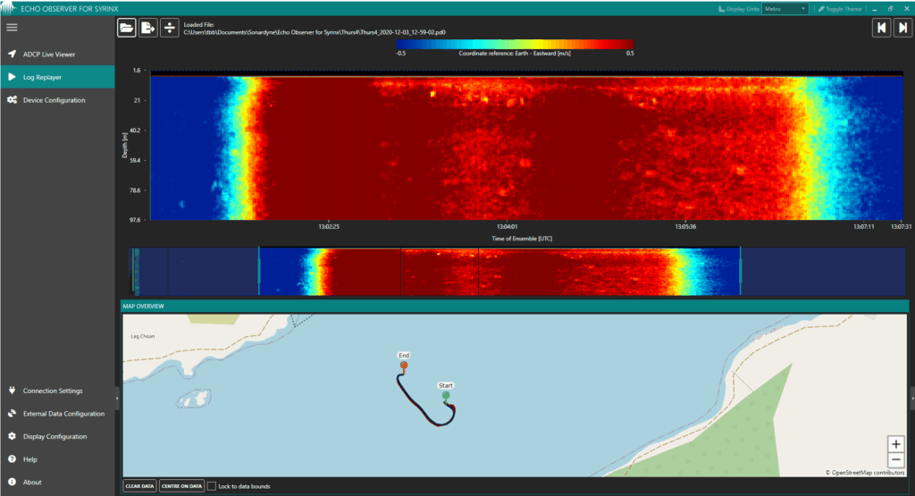
This plot shows the ADCP data without any compensation for vessel velocity.

This plot shows the ADCP data compensated for vessel motion by velocities obtained from the INS. It’s the equivalent to what you would get if you were bottom tracking. The benefit of INS compensation is immediately obvious.
With just the INS compensation we can clearly see fresh water at the surface moving slightly westerly (bright turquoise) while the main body of the water is moving gently eastwards (yellow) with items in the water – moving strongly westerly (blue) and some moving strongly to the east (orange-red). In the plot on the left (without INS compensation), these details are largely obscured by the vessel motion – strongly easterly (deep red). The difference is dramatic.
To recap, ADCPs measure the direction and velocity of water at many depths – the current profile. But if you’re doing that from a vessel you need to be able to remove the vessel speed. Typically, this can be done using DVL velocity, but when bottom lock is unavailable or unreliable, then the INS provides exceptional compensation.
Supporting USV operations in deeper waters
Because of the tight integration of the INS and DVL in SPRINT-Nav, we’re able to gather ADCP data down to 120 m and remove the vessel motion, so you can view the water movement with or without bottom tracking. This could be beneficial for a USV operator working in 300 m, where they can’t achieve bottom lock and still want to know water speed, or where the seabed is moving, such as in the mouth of an estuary.
Something fishy below the waves
After testing out how the world looks with and without INS aiding, we started to look at other features in the water, through our various components. For example, the plot below shows east‑west velocity, again clearly showing the top section of fresh water moving in a different direction to the main body of denser salt water below. But we can also see fish in the water – these are the discrete ‘blobs’ that stand out from the overall water flow.
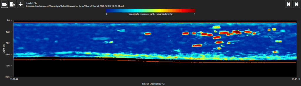
Next, we looked at the same transit, but in velocity magnitude. Again, in the plot below, we can see the fish, and also the halocline – the change in salinity with depth. The halocline is represented by the thin, lower salinity layer (light blue) near the surface and the much thicker layer (dark blue) below, corresponding to higher salinity water. These layers appear in a plot of velocity magnitude because the layers are travelling at different speeds.
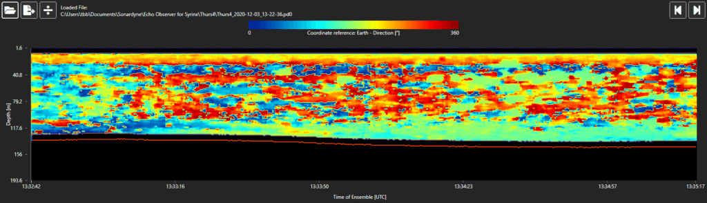
Finally, we switched to a waterfall plot of velocity direction, which highlights the shear between the fresh-saltwater boundary. In this plot (below), the upper layer is flowing west (270°, orange), while the lower layer is flowing approximately west (90°, blue).
Whirlpool imaging
A phenomenon we were keen to observe, and which is very much visible close to Connel Bridge, as you can see in the photo below, is a whirlpool. But while they’re easily visible on the surface, what’s happening beneath the surface? ADCP data is a great way to have a look and we did.
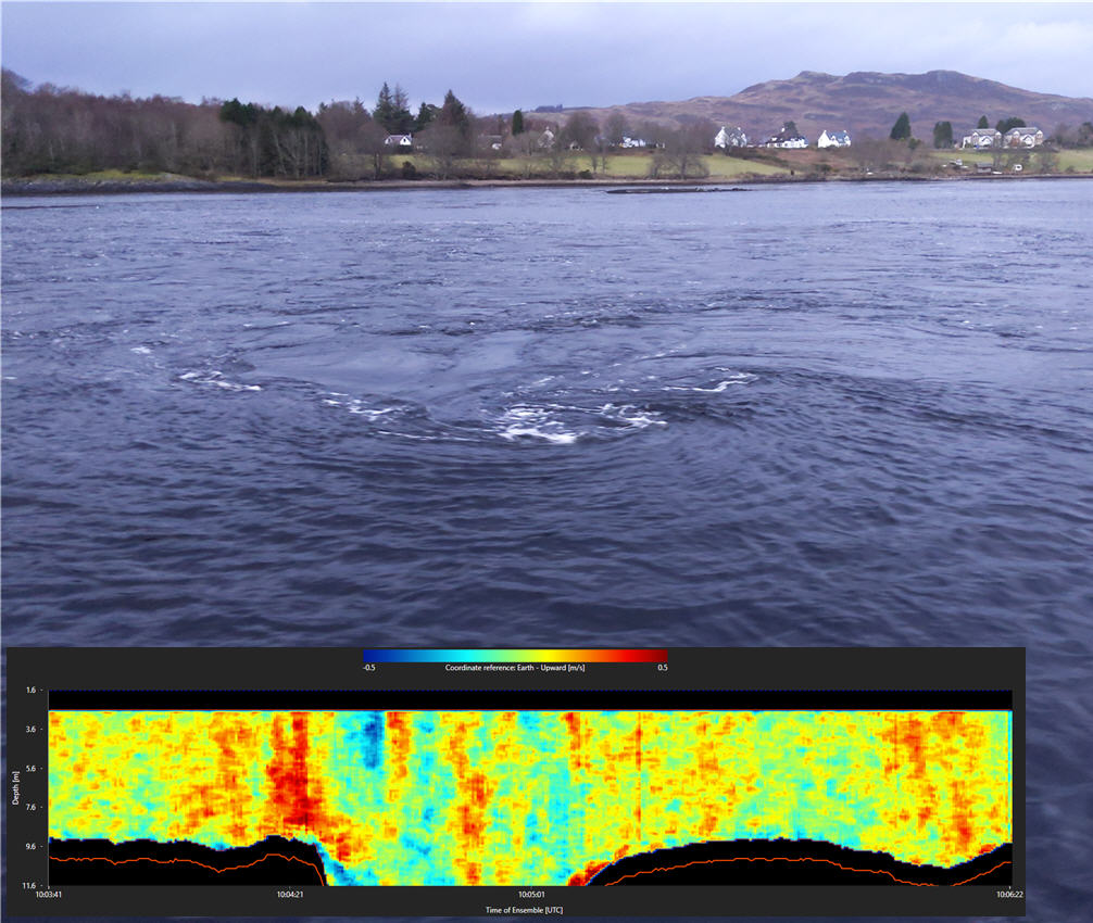
In this waterfall plot within Echo Observer, we’re looking at upward velocity, with red indicating strong upward velocity and blue indicating the opposite, i.e. downwards. This clearly shows the eddies throughout the ~9 m deep water column in this area across the vessel track. In this example, SPRINT‑Nav was configured to alternate DVL and ADCP pings, allowing us to use the bottom‑track data to compensate the ADCP for vessel speed. While we were on deck, we could view this phenomenon on the surface, but also the effects below the surface in Echo Observer, which also showed us the data alongside our vessel position. It was fascinating to watch all of these elements at the same time as we moved over the eddies!
What’s more, as well as the real-time waterfall plots, the data can also be viewed in 2D line graphs, which combine all components of the ADCP data, such as north, east and upwards in earth frame. Echo Observer also allows the data to be exported from the PD0 binary format into a CSV file so it’s easy to use in applications like MATLAB for further analysis.
Going in deep
A key part of our trials was testing the ADCP at depth. The plot below shows water velocity magnitude. The dark blue indicates still or slack water, with a slightly higher speed shown at the surface in a lighter blue. Fish and marine mammals can also be seen in the water as individual ‘blobs’ in red-orange, depending on their speed. And as shown in the plot below, the DVL’s bottom track was locked at about 120 m, as indicated by the red line, and the ADCP profile was also measured to that same depth. The red area just above the seabed is an artefact of the ADCP signals interacting with the seabed.
Viewing the fresh/saltwater boundary
As we travelled around, we often saw the waterfall plot indicating some water traveling eastwards and some west, shown below with red indicating a strong eastward velocity and blue the opposite, i.e. west. This plot, below, is from an area about 38 m deep, where bottom track from the DVL is shown in the red line.
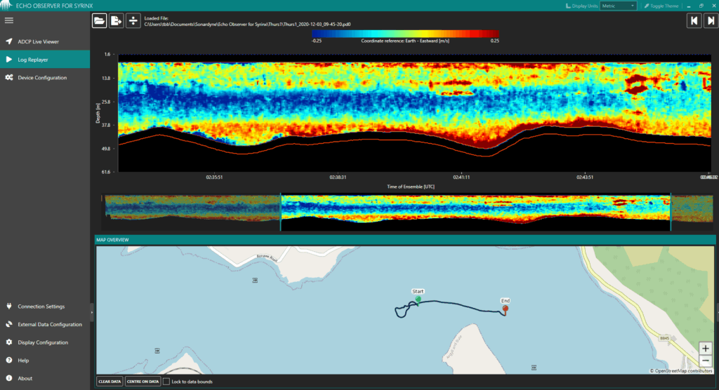
The plot shows a ~15 m deep layer of water moving west at about 0.25m/sec, in blue-green, and above it another ~10 m deep layer of water moving east, at about 0.2m/sec, in yellow-red. This indicated a freshwater‑saltwater boundary, due to saltwater being denser than fresh water. A member of the crew, who dives this area, confirmed you can taste the salinity differences in the water masses!
It’s a great example of the interesting physical affects you get between layers of salt and freshwater, with waves propagating between the different layers and different densities. In fact, the plot even shows substructure within the freshwater layer, indicating the existence of more complicated water properties.
Marine mammals and their wake
Another interesting physical effect that appears in our data is the wake from marine mammals, as shown in this waterfall plot, which is measuring velocity magnitude down to about 32 m.
The discrete regions shown in this plot are marine mammals. For the largest of these, the visibility of its wake reinforced this interpretation and gives us confidence in SPRINT-Nav’s ADCP wake detection capability.
Slack to tidal run
Finally, just for fun, we undertook a series of transits across the same stretch of water starting at slack high tide. Again, the plot shows water velocity increasing in pace, as it falls off slack high tide.

We were pleased with the end results of the trials. We got some fantastic data and achieved current measurements down to 120 m.
We can see many scenarios where this capability – from a single instrument – will be hugely beneficial to projects, from USV operations to offshore dredging. However, we’d most like to hear where you, the user, think this functionality could be best put to use. We’re here to help make it happen. Get in touch if you would like to know more.
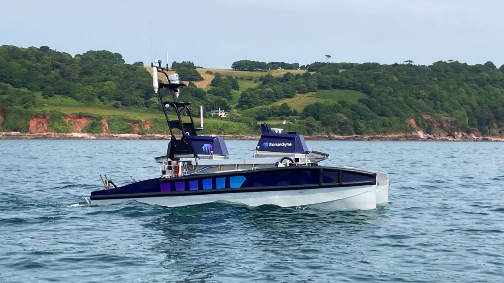
Marine technology specialist Sonardyne has released a new high altitude variant of its market leading hybrid navigator SPRINT-Nav to allow uncrewed surface vessels (USVs) and underwater vehicles to extend their operational envelope.
SPRINT-Nav tightly integrates a Sonardyne SPRINT INS, Syrinx DVL and a highly accurate pressure sensor into a single high-performance solution providing navigation and optional acoustic Doppler current profile (ADCP) functionality.
Sonardyne’s new variant takes this capability to an even higher level; increasing the altitude at which vehicle platforms can work when they don’t have an external position reference, without compromising accuracy.
Operating at 400 kHz, the high altitude variant achieves reliable bottom lock at up to 230 m altitude above the seabed, providing USVs with a highly accurate and robust navigation source, which is critical for, as an example, station keeping applications in coastal surveys where GNSS could be denied or subject to interference.
Installation of the new SPRINT-Nav variant on autonomous underwater vehicles (AUVs) and remotely operated vehicles (ROVs) allows inspections and surveys to be performed at even higher altitudes than previously possible.
In addition, the instrument’s optional ADCP functionality has been extended to 120 m, adding oceanographic data gathering and increased operational capability. This can be especially beneficial in highly dynamic environments and/or where remote vehicles are being deployed from a USV and robust current profile data is required.
The new SPRINT-Nav high altitude variant has already been delivered into the USV market, including as part of a package of Sonardyne technologies being installed on the first wave of Ocean Infinity’s new Armada fleet of robotic vessels.
[blockquote author=” Malik Chibah, Engineering Director, Sonardyne.”]”Our new 400 kHz SPRINT-Nav high altitude variant provides the optimal performance blend, with comparable accuracy but 30% greater altitude to our 600 kHz standard SPRINT-Nav”[/blockquote]
“With higher altitude performance, this new variant of SPRINT-Nav allows USVs to operate in a wider range of maritime environments. UUVs can also operate at higher altitudes above the seabed, across a wide range of operational scenarios in the defence, energy and science sectors. This comes without the loss of accuracy expected of instruments offering the equivalent altitude. For example, you can increase your multibeam coverage rates or also reduce navigation drift during descent and ascent.”
In addition to releasing the SPRINT-Nav high altitude variant, the 400 kHz capability it contains is also now available as a standalone 400 kHz variant of Sonardyne’s Syrinx DVL, which also comes with optional ADCP functionality.
Leading geo-data specialist Fugro has chosen underwater positioning and communications technology from Sonardyne to support its global fleet of uncrewed surface vessels (USVs) and remotely operated vehicles (ROVs).
Fugro will integrate Sonardyne’s Mini-Ranger 2 Ultra-Short BaseLine (USBL) positioning system, configured with the company’s Marine Robotics software extension pack, into its new 12 m-long Blue Essence USV, of which the first vessel will be delivered to Fugro’s base in Perth in February.
Mini-Ranger 2 with the enabled Marine Robotics pack will allow the Blue Essence to be used to deploy, track, command and control the Blue Volta electric remotely operated vehicles (eROVs) and autonomous underwater vehicles (AUVs) as part of inspection, survey and data harvesting projects, all controlled from Fugro’s onshore remote operations centres.
Construction of further vessels that will bolster Fugro’s global footprint are under way at SEA-KIT’s bespoke facility in Tollesbury, UK, where integration of the Mini-Ranger 2, complete with hull-mounted acoustic transceiver will take place.
Mini-Ranger 2 is ideal for use from small vessels, including USVs, where survey-grade positioning performance is required. It can simultaneously track 10 targets at very fast update rates, is quick to install and has a standard operating range of 995 m, extendable to 4000 m. Sonardyne’s Marine Robotics software pack unlocks valuable additional capability when used with a compatible subsea vehicle mounted instrument such as AvTrak 6. This includes secure data exchange and remote control of multiple AUVs deployed in swarm scenarios.
[blockquote author=” Ivar de Josselin de Jong, Global Solution Director for Remote Inspection at Fugro”]”The integration of Sonardyne’s positioning system into our unique remote inspection offering, which combines the Blue Essence USV with the Blue Volta inspection eROV, is key in supporting Fugro’s strategy to lead the development of remote and autonomous solutions for a safer, more sustainable and more efficient approach to the construction and maintenance of marine assets. Our fleet will deliver an entirely remote-controlled inspection solution for the first time in history and this will play a pivotal role in the rapidly growing offshore wind sector.”[/blockquote]
Graeme Buchanan, Sales Manager with Sonardyne in Singapore, says: “We’re pleased to be continuing to support the ongoing transition towards increasingly remote and uncrewed operations across all marine sectors. Enabling entirely remote-controlled inspection with solutions such as our Mini Ranger 2 is delivering safer, more sustainable and efficient operations across the ocean space.”
Quincy, Massachusetts, based underwater robotics innovator Dive Technologies has chosen a complete suite of Sonardyne technologies for navigation, tracking and control of its large displacement DIVE-LD autonomous underwater vehicle (AUV) programme.
The DIVE-LD AUV is being developed to meet a wide range of long-endurance mission requirements, across the commercial, research and defence sectors. To support long-distance and long-duration navigation, while minimising complexity and payload space consumption, the vehicle is fitted with Sonardyne’s industry leading hybrid navigator SPRINT-Nav.
For underwater positioning and acoustic communications, the DIVE-LD is fitted with Sonardyne’s AvTrak 6 – a combined transponder, modem and emergency relocator beacon all in one. To cover all its concepts of operations (CONOPS), including tracking and communication during development and testing, Dive Technologies has also acquired Sonardyne’s most capable Ultra-Short BaseLine (USBL) system, Ranger 2, with its latest, compact Gyro USBL.
The DIVE-LD AUV, measuring 48 inches in diameter and 19 feet long and designed for operations down to 6,000 m water depth, is currently in production in the US with sea testing ongoing in New Bedford.
Founded in 2018, Dive Technologies’ rapid development program has included support from the Defense Advanced Research Projects Agency (DARPA) and technology partnerships with organizations including the Center for Marine Autonomy and Robotics at Virginia Tech.
A key part of the development has been to opt for high-performance, off-the-shelf systems, such as SPRINT-Nav for navigation, allowing the company to focus on building certain customized systems in-house. SPRINT-Nav, which is available across a range of performance levels, all in the same form factor, also supports Dive Technologies’ focus on mission adaptability, as does Ranger 2.
Tim Raymond, Dive Technologies’ Director of Research and Development, says that Ranger 2 offered a proven platform with a track record across a wide range of use cases, offering flexibility and scalability in functionality and complexity.
“With a new development effort underway for Dive Technologies’ DIVE-LD autonomous underwater vehicle, we had a wide range of use cases in mind and needed a single system capable of supporting the various mission sets we had in mind,” he says. “We also needed a topside system which could scale in functionality and complexity with our vehicle as we continue to add features and capabilities, from our initial testing where our needs were just tracking and emergency commands, to more advanced features such as USBL aiding and SMS transmission of vehicle and data health metrics.”
[blockquote author=”Tim Raymond, Director of Research and Development at Dive Technologies”] “Ranger 2 is a good fit for both of these needs and it has enabled us to meet our challenging goals of simultaneous development and testing while maintaining consistent and impressive performance even in challenging operating conditions. The system has proven reliable, easy to use, and portable to support mobilisation on a variety of support vessels.”[/blockquote]
“We’re excited to see the work that Dive Technologies is rapidly progressing through the DIVE-LD program,” says Dan Zatezalo. “The wide range of missions they’re targeting as well as their focus on highly-scalable open software and hardware architectures aligns with where we see the industry heading. Our own philosophy has been about integrating and simplifying our systems by utilizing a common platform and software architecture, while also improving performance and offering flexibility and scalability. We look forward to seeing the DIVE-LD performing.”
Ranger 2 is Sonardyne’s highest performing USBL system, capable of simultaneous long range target tracking, dynamic positioning (DP) and subsea communications. It is being supplied to Dive Technologies with Sonardyne’s new compact Gyro USBL, which combines the vessel heading, pitch and roll data that’s critical to USBL system precision, with an acoustic transceiver in a single housing, supporting system simplification and ease of mobilization.
SPRINT-Nav combines Sonardyne’s SPRINT INS sensor, Syrinx 600 kHz DVL and a high accuracy intelligent pressure sensor into a single housing, making it one of the smallest combined inertial navigation instruments on the market. SPRINT-Nav’s tight integration of raw sensor data at a low level provides unprecedented navigational performance and precision for subsea vehicles, consistently outperforming competing systems in customer trials.
Built for simple integration on medium to large AUV platforms, AvTrak 6 combines the functions of transponder, transceiver and telemetry link in one low power unit, leaving more payload space and power for other instruments. It enables AUVs to undertake simultaneous LBL ranging, USBL tracking via a surface vessel and robust telemetry for AUV to vessel and AUV-to-AUV communications.
We’re looking back on 2020 – and what a year it’s been. Due to the Covid crisis, remote support has become a key way we have been able to continue to serve you, our customers, to keep your operations on track. But it’s not all been about what we can do remotely – our engineers have also been out supporting customers in the field too.
We took a look at our numbers and thought you might be interested. Our remote survey, engineering and training services went from being a small part of our customer offering prior to the pandemic, to now providing the equivalent of a person constantly, every day. We are supporting our customers remotely across regions spanning from Asia to North America. It’s been quite a steep learning curve to make the transition to remote support and services, but it’s also one we suspect many of you will recognise as you’ve also had to pivot to this new world.
On-site support continues
Naturally, our face-to-face, on-site support dipped over the same period. But, alongside increasing our remote support and services, across survey, engineering and training, we’ve still continued to provide our engineering and survey personnel to customers on site, whether that’s at the dockside, naval base or offshore, from Brazil to Baku. And those numbers have increased as, alongside you, we have worked through each change to Covid restrictions, at home and abroad.
The range of services provided remotely and in-person has also varied hugely, from calibrations and installation project delivery support to real-time survey operations support services. It all depends on client requirements. Back in June, for example, we were able to support P&O Maritime. They required a CASIUS calibration of a replacement HPT 5000 onboard their multipurpose vessel the Topaz Tangaroa while it was in Vlissingen in the Netherlands. To keep their operations on track, we helped them perform the calibration 100% through remote support.
Real-time SLAM – remotely
In August, our training team provided remote training in our new LBL and INS Fusion 2 survey software for a client crew in the US. That meant they were then able to join their vessel in the Gulf of Mexico and roll-out the our survey system on a live project. To reduce the risk of introducing a new system, we provided real-time online remote support and services from our Survey Support Group. This isn’t just having someone on the phone. We were able to supply our Remote Operations Access Module (ROAM) to the vessel so that our surveyors onshore, in the UK, were able to remotely access the Fusion 2 system throughout the project, ensuring everything went smoothly by offering the same service they would normally do in person, remotely. Doing this not only saved logistics headaches – by being able to use locally available surveyors on the vessel – but also meant they saved significant time on the job because they could use the new time saving features in Fusion 2 such as real-time SLAM calibration. That new functionality offered a significant saving on a 1,300 m water depth project.
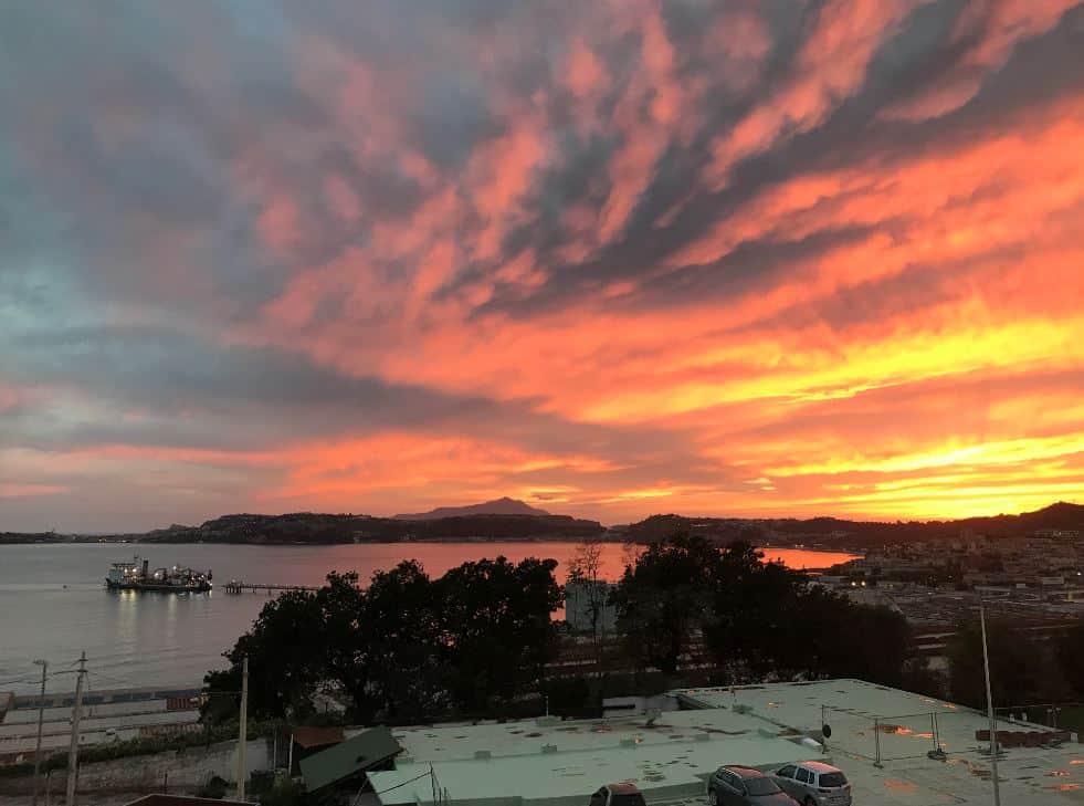
On other occasions, such as for a recent cable lay vessel CASIUS, we were able to send out one of our engineers to make sure it went ahead glitch free, enabling the vessel to get to its next project with minimal downtime. We mostly mention this project because, while on the visit offshore Italy, our engineer took these lovely photos, which we wanted an excuse to share (you might, just, be able to spot the vessel he was visiting)!
He also shared his thoughts, that there are undoubted benefits to having a field engineer or surveyor physically supporting survey operations or a CASIUS calibration. One of those, in the case of a CASIUS, is being able to verify that the motion reference unit (MRU) has the correct Sonardyne sign convention – which is easiest checked visually, by comparing the movement of the vessel to the pitch and roll values reported in the Ranger 2 USBL system.
Tailored support services
However, what all of these projects show is that the right support for each case can be provided so that a CASIUS, installation support or required training doesn’t upset operational schedules and the customer can receive the same support or service whether it’s done in person or remotely. If you want us to send a specialist offshore, we will. Where we physically cannot do that, we will undoubtedly be able to provide the same support remotely, making sure your projects continue to move forward.
We also don’t think this is just about dealing with the constraints that have been placed on us throughout 2020. Many of these trends, the move towards more remote operations and support, has been coming for some time and we’ve been in discussions on the future of remote support and operations for some time. It’s just been accelerated. So the significant upside to all of this is that we now have a much broader suite of support options for you, not just for now, but into the future, in person and remotely, and we’ll continue to evolve these to meet your needs.
From operational survey support services, where we can remotely dial into your Fusion 2 system, through to field support offshore or at the dockyard for a system upgrade, we’re able to provide a dedicated service to you. Of course, our usual day-to-day customer support will also always remain in place!
Find out more about these dedicated services at the links below.
Remote Field Support
Operational Survey Services
Training
So, 2020 has been an unusual and busy year. Like you, we’ve been dealing with the challenges the pandemic has thrown at us. We’ve also found new solutions that will continue to be used when we come out of the other wise of this world we’re in. And we’re confident it will be a better world.
Get in touch to find out how we can support you.
My two previous blogs in this series looked at how unattended sensors can help solve some of our 21st century warfighting challenges, the sensors that exist today and what you need to think about to make them work. It’s now time to take a deep dive into what goes into making them fit for persistence across the ocean space.
There are three main elements that go into making persistent sensors work: what’s on the inside, i.e. the sensors, processing power, modem capability and batteries; the materials and form factor of their housings; and deployment options. Let’s start with what’s on the inside.
Onboard sensors
We already offer a wide range of sensors integrated into our instruments, including acoustic Doppler current profilers (ADCPs), inclinometers, and pressure, temperature and speed of sound sensors. These sensors help to characterise the environment and in turn inform the mission; helping to fine-tune other sensors and our acoustic systems.
But the options for sensing are almost endless. Third party sensors can be connected to our unattended instruments via a connector. We support a range of standard commercial-off-the-shelf subsea connectors and can accommodate bespoke solutions too. Our connectors have ports for power, RS232, RS485, CAN Bus and Ethernet. We can work closely with your team to accommodate the right solution.
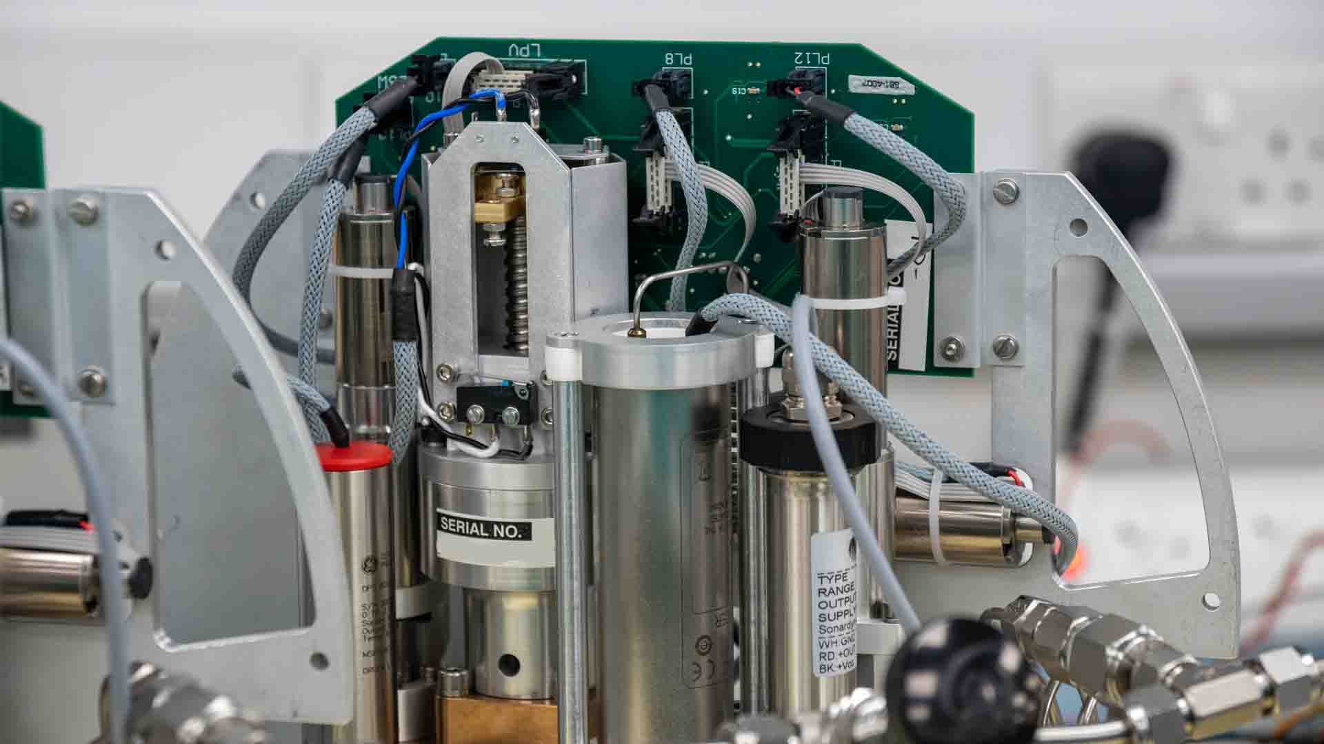
Sensors Lab
How do we ensure success? At Sonardyne, once we have designed an unattended sensor, we test, test and test again. The oceans never ask for forgiveness. Our sensors lab enables us to carry out accelerated life-cycle tests for all sensors that we plan to use; at the right temperatures and pressures. This means we can stress test instruments to the point of failure, which we do at the proof-of-concept stages.
It means we can also characterise the performance of sensors over time, becoming familiar with their performance and predicting any possible degradation, remembering all the time that we need to design for longevity. We also conduct in-water tests and have a dedicated in-house team whose job it is to identify and quantify any errors before our systems are deployed.
On board processing
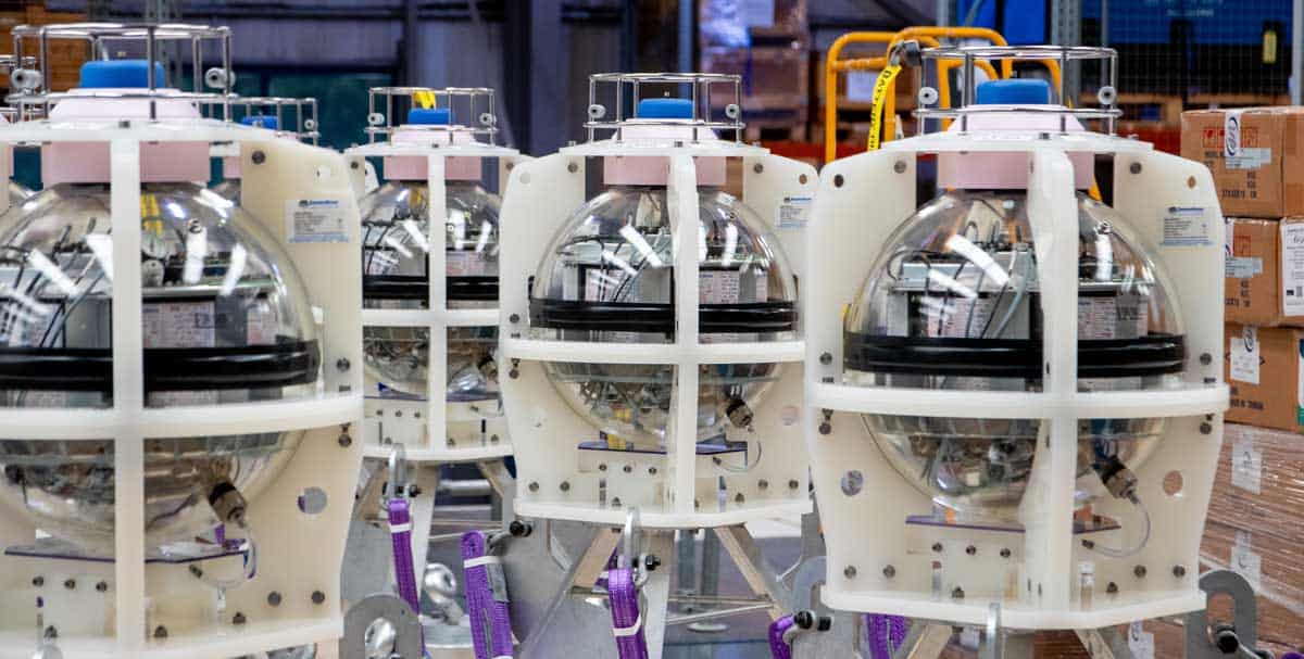
Data gathering requires data storage and, increasingly, also processing capability, in order to provide the relevant data that’s required. Our most basic offering stores sensor data in SD cards or equivalent. The data can then be harvested via an acoustic or optical interface. When glass sphere housings are used, the SD cards are duplicated and all data products are stored in two separate and identical repositories.
Edge processing is available with our advanced data acquisition and processing system (ADAPS) option. This highly capable processor can run sophisticated user-specified algorithms, as well as simple data analysis, such as min/max/mean statistics and thresholding for alarms and critical event reporting. By reducing high-bandwidth sensor data to small, critical packets, we can efficiently manage power consumption. That means longer deployment times can be achieved from the internal battery pack. Furthermore, using the sensor’s integrated acoustic modem, “through the water” updates to the edge processing algorithms provides ultimate flexibility and performance over the entire life cycle of the deployment.
Battery options
To be successful, unattended sensors need to work remotely and persistently for extended periods of time. The battery technology on-board will play an important role in helping extend the length of the mission. For short deployments, we use tried and tested Alkaline batteries. A single pack can provide up to 54 Ah. But by using glass sphere housings, we can pack in even more batteries. In this configuration our typical capacity ranges from 180 Ah to 505 Ah. The latter has demonstrated operations lasting for well over 10 years.
Choosing the right battery option depends on the concept-of-operations. Higher capacity adds weight to the instrument. However, it also enables our instruments to gather, process and share more data. At Sonardyne, we have developed in-house algorithms to provide accurate estimates for battery life. Once we understand the requirement, we can configure the right battery.
Materials
Of course, it’s not just what goes into the sensor that matters. Biofouling and endurance are high up on the list of our headaches. Learning how to select the right materials for operation across the world’s oceans takes time. As we have seen in my previous blog, biofouling is a constant threat, particularly where our sensors interface with the water, through which we are sensing.
Since most unattended sensors remain stationary, anti-fouling solutions used on boats or ships that are typically reliant on flow do not work as well for us. At Sonardyne, we conduct continuous trials into materials and anti-fouling solutions. The battle never ends, year-on-year we improve our materials selection process and come up with neat tricks, like copper tape to prevent fouling.
To prevent corrosion, we have a few options. For shorter deployments, we use hard anodized aluminium. For longer deployments, titanium is iron free and will not rust. It is ideal for when you want a sensor to remain in situ for 10 years or more. But it’s costly.
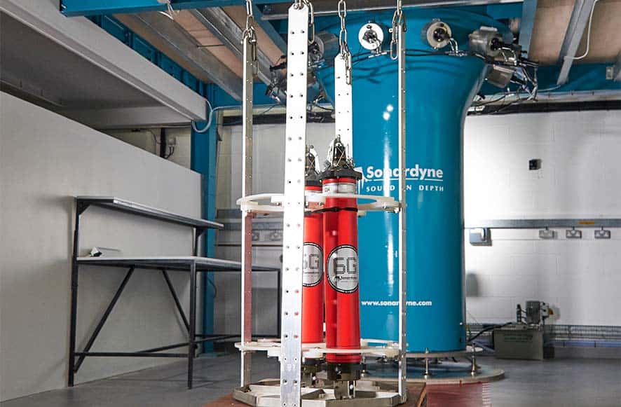
To ensure they can withstand the rigours of underwater operations, we design and push our materials and instruments to their limits. Using our unique hydrostatic pressure test chamber measuring at 750 mm diameter and 2000 mm tall, we can generate 630 bar of pressure, simulating depths of well over 6,000 m. We can cycle the instruments many times, simulating multiple deployments. We also use temperature regulated chambers to cycle through different temperatures at different rates. We need to, as our instruments are as likely to be sitting on a deck in the Arctic as they are to be found in Tropical seas. How the materials behave as they are dropped into the water and are then submerged is vital information that we use to help us choose which ones to use.
Deployment options
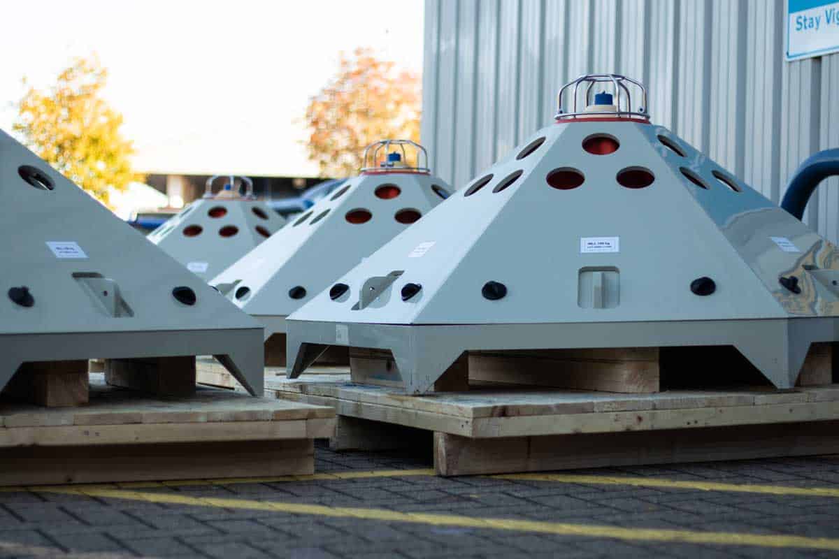
The considerations do not end there. If we want to be truly unattended, that means – once deployed – we want sensors to remain on the seabed throughout the life of the mission. To do this, we offer a range of options from floatation collars (used to moor sensors on the seabed and to easily recover them) to glass spheres on tall frames that can freefall to the seabed and are deployed for periods of more than 10 years.
Our systems are made to operate at all ocean depths from very shallow waters using anti-trawl frames to the depths of the Mariana Trench. Our deployment systems can be built by us or our customers under license – anywhere in the world. Speak to us to discuss your requirements.
Acoustic Data Harvesting
So now you have your sensor. It’s been deployed and it’s gathered, processed and stored data you would like to access. What’s next? Our unattended sensors set themselves apart as they are equipped with leading acoustic communications.
Our underwater acoustic modems are used to regularly harvest data from these sensors. This can be done from either the surface or a nearby unmanned underwater vehicle (UUV). The protocols are secure, ensuring that the sensors respond exclusively to the asset owner; preserving battery and keeping the system undetected while it is not being interrogated.
We can also tailor the waveforms to make them difficult to detect and exploit. Enabling us to send sparse acoustic commands through a network. This means that, if our edge processing pulls the trigger, the sensor can send a pre-defined message. Alternatively, we could acoustically command an actuator to have the sensor float to the surface. Our sensor then becomes a data pod waiting to be recovered or capable of transmitting information when it reaches the surface.
If covertness is not a mission requirement, our commercial acoustic protocols are designed to operate between 14 kHz to 34 kHz, supporting a rich range of telemetry schemes. That translates to two-way communications anywhere between 200 bps to 9,000 bps over tactically significant ranges of up to 12 km. These signals can also be used in support of navigation systems for friendly third-party underwater vehicles (i.e. UUVs) in the vicinity of the sensor.
If your platform must remain covert, then optical free space modems may be a better option. These modems work over shorter ranges, from approximately 5 m to up to 150 m, and can be used to transfer between 10 Mbps to 600 Mbps. They work in the UV and visible light spectrum and work best at depth, away from the sunlight’s interference. Because they work over shorter ranges, it means enemy combatants really need to know where to look for them to find them. As they will only respond to a known modem, they can remain hidden for prolonged periods of time.
Taking the next steps
So, in the first blog in this series, I looked at how achieving scale in the underwater domain doesn’t have to come at a high cost. Unattended sensors can monitor choke points, provide persistence and guide the underwater vehicles that are extending our naval forces’ reach. In the second instalment, I covered the challenges we face when deploying these sensors. In this final blog, I’ve looked at what goes in to making these systems so that they will offer the persistence you require. What more do you need to know?
If you have a requirement for persistence in your underwater battlespace, we can help. Get in touch to discuss your needs.
Sonardyne technology has been selected to support the world’s largest and most environmentally sustainable fleet of ocean-going, multi-role robotic vessels, which is being launched by marine robotics company Ocean Infinity.
Sonardyne systems will provide part of Ocean Infinity’s new Armada fleet with key sensor technologies for underwater platform navigation, tracking, control and communications, as well as ensuring uninterrupted surface navigation, even when global navigation satellite system (GNSS) services are degraded or denied.
The Armada fleet will mark a major technological advance, providing sustainable services to all corners of industry from offshore energy, to logistics and transport. The innovative, low-emission robotic fleet that can be launched from any shoreline on the globe was unveiled in February this year (2020), and will initially see 17 bespoke designed state-of-the-art uncrewed vessels added to Ocean Infinity’s existing robotics fleet.
The vessels, initially measuring 21 metres and 36 metres long, will be able to perform offshore data acquisition and intervention in both shallow and deep water operating regions. The vessels will use a range of underwater platforms, including remotely deploying autonomous underwater vehicles (AUVs) and remotely operated vehicles (ROVs).
Sonardyne’s acoustic communication and inertial navigation technologies were chosen to support Armada because of their performance and flexibility across a wide range of water depths and environments, supporting operations across all sectors in even the remotest locations.
The package includes surface and subsea navigation sensors to remotely support deployment, operations and recovery of underwater robotic systems from an uncrewed vessel, from anywhere in the world. That includes being able to accurately track and control multiple robotics systems simultaneously and provide water current profile information, as well as support vessel dynamic positioning during critical phases of an operation.
Uniquely, the systems also provide navigation redundancy in the event of GNSS outages, which could occur while operating in multipath or shadowed environments, such as fjords or near large structures or where signals are deliberately interfered with.
Delivery of Sonardyne equipment for the first wave of Armada fleet vessels will be made by the end of this year. Further deliveries will be made through 2021.
Alan MacDonald, Sales Manager, Sonardyne, says, “Over recent years, we’ve been focussed in Sonardyne on developing the flexible technologies that are required to support the revolution that is taking place in both surface and subsea marine robotics. Consequently, we’re very pleased to be part of Armada’s pioneering vision to deploy robotics at scale. These systems will help a wide variety of industries to reduce how many people they need to send to sea as well as dramatically reduce CO2 emissions, by deploying these smaller, more efficient vessels out.”
[blockquote author=” Dan Hook, Managing Director, Ocean Infinity”]Our expert team of robotics specialists selected Sonardyne as the clear choice for our robotics ships, to provide underwater navigation, tracking, control and communications and that additional layer of positioning security in areas where GNSS signals might be obscured. We look forward to a long-term working relationship with Sonardyne, as we grow our fleet.[/blockquote]
Initially, all of the first tranche of Ocean Infinity’s Armada vessels will be fitted with Sonardyne’s Ranger 2 Ultra-Short BaseLine (USBL) system augmented by the company’s Marine Robotics Pack. This combination provides remote all-in-one tracking, communications and control capability for underwater deployed robotics so that even more operations can now be done from shore.
These robotic vessels will also be fitted with Sonardyne’s industry leading SPRINT-Nav hybrid navigation instrument, to provide continuous, uninterrupted navigational aiding to underpin safe remote operations, even if GNSS service is impaired due to their remote location or nearby infrastructure. In addition the system produces profiled water column data, which is particularly important during the deployment and recovery of subsea robots.
Wideband Sub Mini 6+ tracking transponders and SPRINT-Navs will also be fitted to the ROVs being deployed and operated by the Armada fleet.
Ocean Infinity expects the first Armada vessel to be delivered in 2021 and, along with the remainder of the fleet, will be controlled and operated by experienced mariners via satellite communication from onshore control facilities in Austin, Texas, and Southampton, England.
In my last blog, we looked at how unattended sensors could help to solve some of our 21st century war fighting challenges, not least how to maximise the use of our crewed and uncrewed assets. We also showed how sensors already exist that can meet those challenges today. In this blog, let’s look at what we need to consider to make them work for you.
There are three things you need to understand:
- 1.Nature is against us
Location: We mean it. Live organisms thrive in shallow waters. It doesn’t take long for biofouling to occur. Typically, this starts with the formation of biofilms, followed by the adhesion of micro-organisms. In shallow water environments, at higher temperatures, it takes just three weeks for biofilm to form and then attract larger colonizers, which in turn attract much larger organisms causing macrofouling. There is little that can be done once the larger organisms take hold, other than recover the instrument and physically remove them. In time they will affect sensor performance and may even stop sensors working altogether. In some regions, biofouling can limit effective deployments to fewer than three months. In cooler and deeper waters, the rate of bio-fouling growth drops, making longer deployments possible. Where an unattended sensor is deployed and how biofouling may affect it needs to be considered as this will determine the duration of deployment.
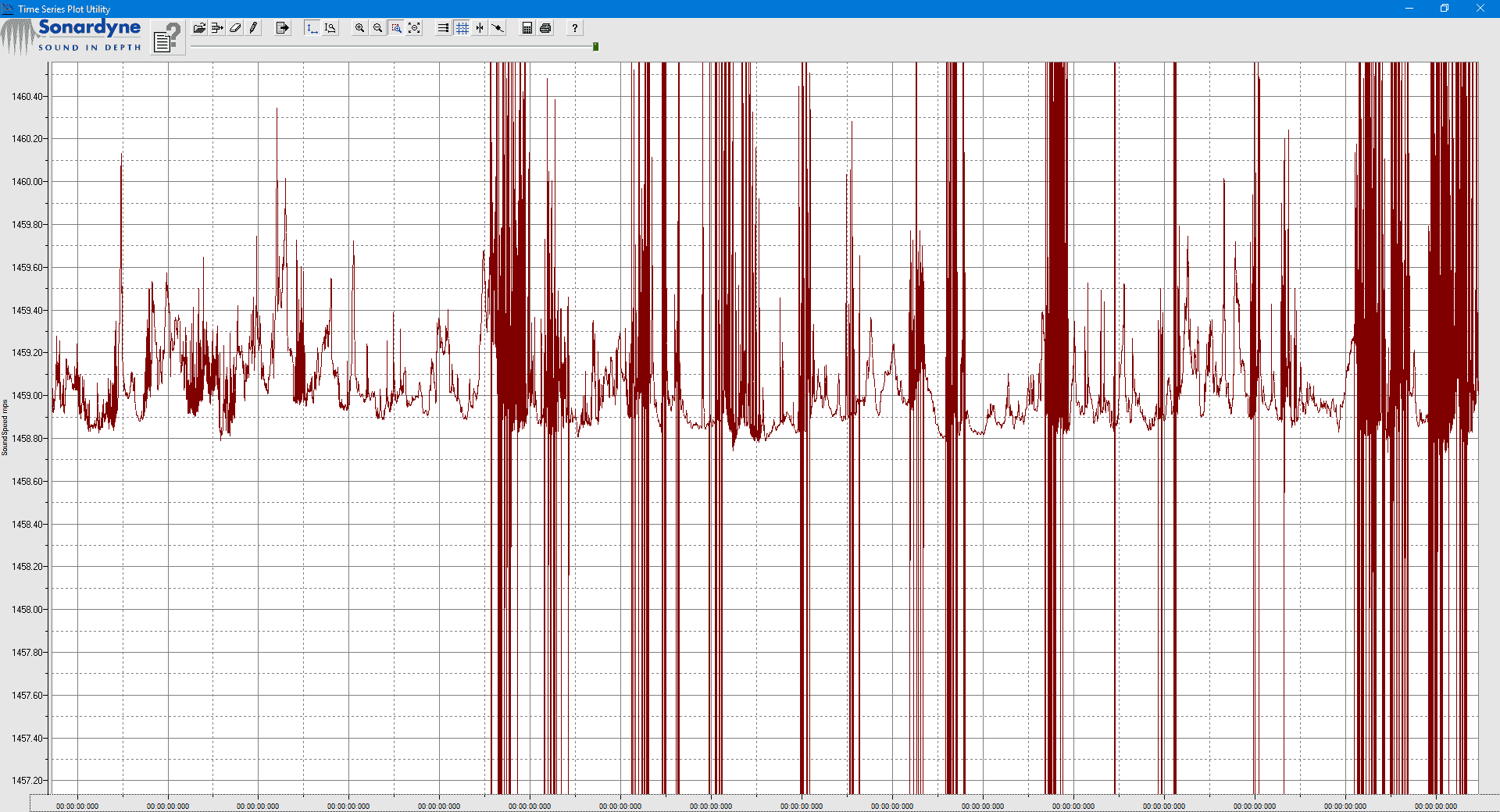 The impact of biofouling on a sound velocity sensor can be very clear.
Materials: Choosing the right materials to build your instruments with can also impact biofouling growth rates. In addition, the right materials are also critical to ensuring your instruments do not corrode. Iron corrodes when exposed to water. Any material with iron in it is subject to corrosion. Over time, even stainless steel will corrode and rust. For long-endurance missions, the design and manufacture of underwater unattended sensors needs to factor in these considerations to ensure that systems remain corrosion free.
Pressure: Then there is pressure. As we dive, we add about one atmosphere of pressure for every 10 m of water depth. Sensors must be designed to both withstand extreme pressures at thousands of meters of water depth, but also to rapidly cycle through pressurisation and depressurisation, as they are deployed and recovered. This is no mean engineering feat.
Seabed conditions: The seabed can be an unforgiving place – it is varied and complex. Unattended sensors can sink through mud or sand. Corals and rocks can obstruct your line of sight and act as reflectors to acoustic sensors. It is not always flat either and deploying a sensor on a slope or close to a cliff could have an impact on your operations.
Commercial activity: Unfortunately, it is not just nature we have to contend with. Interaction with commercial fishing activity can be a challenge. Many underwater sensors have ended up caught in fishing gear. We know, because we’ve had them knock on our door claiming salvage rights for some of our commercial instruments!
 Anti-trawl frames are used to prevent fishing interaction.
- 2. Design for endurance
Delivering an underwater sensor to the bottom of the ocean is analogous to deploying a satellite in space. Design practices are similar because the choices we make today are going to be ones we have to live with for the next 10 years. This means there is no room for error. The electronics, the batteries, the connectors and the subsea housing all have to be up to the task. Making the right decisions comes with experience, but also by following practical engineering principles.
 Long endurance, tried and tested.
Start by modelling your operations. Modelling the environment and how your instruments will interface with it is critical as it enables us to work through concepts and designs ahead of fabrication and testing; enabling us to quickly consider new technologies that keep rapidly evolving around us.
Make sure you conduct in-water tests. Once your systems are designed and fabricated, they need to be rigorously tested to their breaking limits. This is our chance to understand the envelope in which they will continue working. Use pressure chambers, vibration tables and temperature-controlled facilities. Consider accelerated cycle testing. Use proof-of-concepts.
Once you are ready, it’s time to go out to sea and deploy your instruments. While typically not as expensive as launching a satellite, this is still a costly endeavour requiring significant planning and effort. It needs to be right.
- 3. So much data
A sensor deployed at sea for 10 years can gather a lot of data. Exactly how much will be limited by the amount of memory on your storage device. Running out of data storage can be avoided by carefully considering which data to store and at which sampling rate. Continuous sampling of data typically also drives higher power consumption, draining valuable battery resource.
This is why edge computing is becoming so important. On-board algorithms can be used to determine at which rate to sample, increasing the frequency if certain events are triggered. On the other hand, processing raw data and turning it into useful information massively reduces storage requirements. A good unattended sensor should be equipped with the capability to store and process all data or store only the useful information.
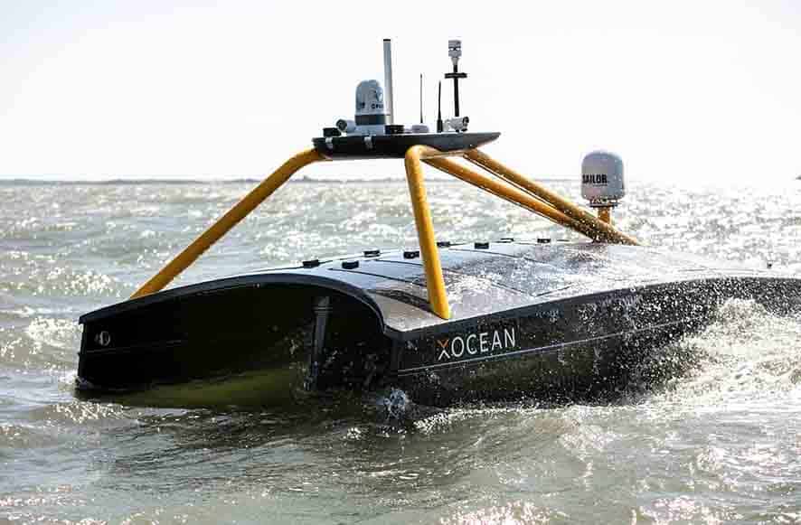
Information can also trigger events. For example, the unattended sensors can be made to release data pods that float to the surface to relay information. Alternatively, they may contact nearby unattended sensors in a subsea acoustic network to hop data from out in the field to a base station. For certain missions, data can be harvested from unattended sensors using uncrewed surface vessels (USVs) or uncrewed underwater vehicles (UUVs) and then the sensor’s memory banks cleared, to continue the mission beyond its original design. In all cases, you need to consider what information is required and what data you need to get it.
 Collecting your data with a UUV or USV offers more options
Making sensors work for you
Unattended sensors are difficult to engineer, but ultimately it’s worth the work. They can support a multitude of missions such as oceanography, anti-submarine warfare, intelligence, surveillance, target acquisition, and reconnaissance (ISTAR) and field deployed ranges.
Want to find out more about our capability? Join us in the next instalment of this series or get in touch.
Missed the previous instalment? No problem, click here
At Sonardyne we are experts at manufacturing and deploying sensors underwater for prolonged periods of time. We offer solutions that are ready to be deployed now. We configure them with modular building blocks meaning that we can work with customers to meet new requirements. In this series of blogs, Ioseba Tena will be looking at examples of long-endurance sensors we can deploy today, why it’s perhaps not as easy as you think to do this, and, finally, a closer look at how our systems are built. Let’s get started.
Submarines have been a persistent threat since their invention. They are capable of operating while remaining undetected and, therefore, projecting force in remote locations. Since the introduction of nuclear-powered systems, they have been able to remain on prolonged deployments. Today, the threat no longer stops there. Unmanned underwater vehicles (UUVs) and a new generation of extra-large UUVs (XLUUVs), with increased range and more capable payloads, are now being introduced to support incumbent nuclear submarine fleets.
Traditional anti-submarine warfare (ASW), while effective, requires significant investment and ties up our warfighting ships – our nations’ prized assets – to the task of trailing possible contacts. As the number of threats proliferate, we become limited by our ability to grow our fleets. This means we need to find new ways to achieve scale.
Leveraging uncrewed systems for ASW operations
Our own unmanned systems can come to the rescue, helping us to project our own strength and our ASW capability, by detecting threats further away and providing us with the opportunity to react to them sooner; informing our fleet before the threat reaches its target.
What better way to do this than deploying unattended sensors at choke points to help monitor persistently or even to have them support our XLUUV fleet in finding its way? They can be part of the ASW mix, by passively monitoring known routes. Alternatively, they can be used by XLUUVs to upload and download data or take/adjust their marching orders based on recent observations.
Today’s unattended sensors can be formidably capable. We have been operating them for a long time in the commercial and ocean science sectors. Our close to five decades of experience in instrumenting the underwater domain has seen us deliver systems in all types of environments in support of everything from oceanographic missions and long-term geological studies to persistent monitoring of subsea assets. The technology is field proven and can change the game.
What can our unattended sensors do today?
Take for instance our Pressure Inverted Echo Sounders (PIES) used in support of oceanographic missions and measuring average sound speed in the water column. PIES can be configured for autonomous monitoring over periods of several months or multiple years. PIES use an up chirp to accurately measure two-way travel-time through the water column. Simultaneously, they also measure pressure at the seabed. Pressure measurements are converted to depth to find the acoustic distance travelled from the seabed to the surface and back again. By combining the depth and travel time, the average sound speed in the water column can be calculated. An embedded acoustic modem allows you to retrieve that data – i.e. two-way travel-time in seconds and pressure in kilo Pascals.
By strategically deploying arrays of PIES we can persistently monitor sound speed profiles across a large body of water. This data can be harvested using our acoustic modems mounted on surface assets like uncrewed surface vessels (USVs) and used in direct support of ASW operations.
Autonomous navigation anywhere
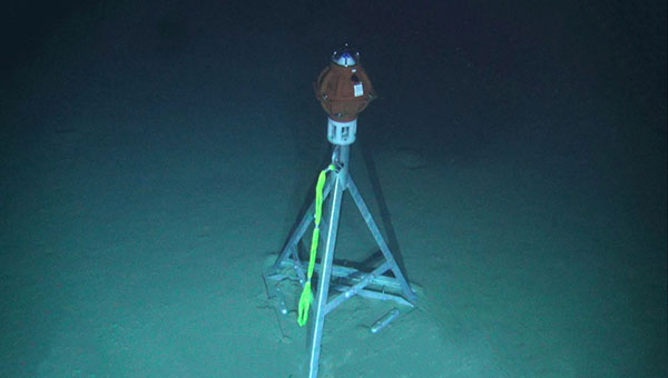
If you need to support underwater navigation, our Autonomous Monitoring Transponder (AMT) is a long-endurance transponder, extensively used for subsea survey tasks and capable of autonomously acquiring acoustic ranges and sensor data without surface control. It can be used to provide a range and a local navigation reference in aid of inertial navigation systems; providing a constant reference to any underwater traffic.
- Deploy it anywhere for prolonged periods of time.
- It can be programmed to wait in silence until activated by a known acoustic signal to then provide a range to a known location, which can be used as a navigation aid.
- It can be programmed to provide updates at regular intervals.
- The AMT can be used as a forward deployed navigation outpost, providing a used to aid the navigation of XLUUV systems.
- It can also be used in support of surface craft navigation when GNSS denial is a threat.
- Surface craft can be equipped with ultra-short baseline navigation systems and navigate relative to an AMT on a known location.
We have decades of experience designing, manufacturing, deploying and recovering unattended sensors. It is in our DNA. PIES and AMT are just two. Do you have a mission in mind? Get in touch with us and we will be happy to explore what is possible.
In the next instalment, I’ll take a look at what actually goes into making these sensors. Yes, it is as hard as you might think.
Over the past three years we focused heavily on building our latest obstacle avoidance sonar. We set ourselves significant targets. We wanted our latest forward looking sonar (FLS) to do everything and more than our previous FLS, enabling navigation in challenging environments, such as uncharted or dynamic waters. But we also wanted to design a system compact and low-power enough that it could be easier to install into smaller vessels – even swimmer delivery vehicles (SDV) or uncrewed/ unmanned surface vessels (USVs). And we wanted it to come with a simple, intuitive interface with automated alarms and easy to interpret seafloor bathymetry so that users, from oil tanker captains to underwater gear clad SDV operators, are always aware of their underwater environment in a way that’s easiest for them.
Collision avoidance with Vigilant
The result is Vigilant. We like it and our customers, from Superyacht to SDV owners, do too. But we’re always really happy to try it out on new vessels and in new environments. So we were hugely excited to be invited to demonstrate Vigilant to the Stiletto Maritime Demonstration Platform at the Naval Surface Warfare Center Carderock Division (NSWCCD) in Virginia, US. Stiletto was looking, specifically, for capability demonstration of real-time obstacle avoidance for high-speed landing craft in shallow waters, using vessel-mounted surveillance systems.
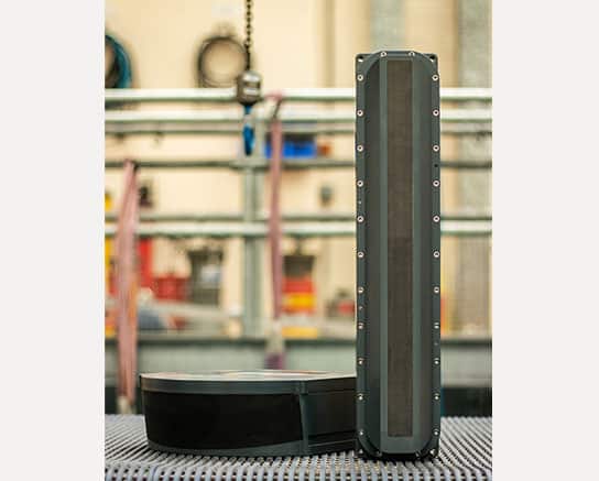
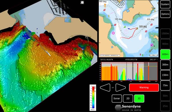
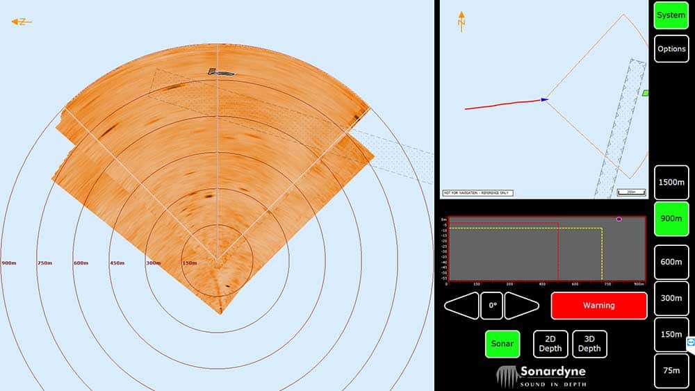
Just in case you don’t know, Vigilant is our long-range, forward-looking sonar for seaborne obstacle avoidance. It works by transmitting acoustic energy into the water, through a 90 degree azimuth and through a vertical plane down to 100 m water depth – deeper than any other system in the market. It then listens for the sonar returns. These are used to detect objects in the water column out to as far as 1,500 m (4,921 ft) away in Vigilant’s Sonar made. In 3D mode, frequency encoded sonar returns are processed through a unique Altitude Confidence Filter (ACF) in order to create a really easy to interpret 3D visualization of the seabed depth and bathymetry and depth of objects in the water column, all out to 600 m (1,968 ft) down to 100 m depth. This data is also retained, so it’s easy for navigators to retrace their steps.
3D bathymetry and long range obstacle detection
The user can seamlessly toggle between Sonar and 3D mode, depending on their navigational requirements – with zero delay in the data displayed on their graphical user interface. So, in open waters, its configurable CAD markers can alert the operator (or a third-party AI based processor) to the presence of a navigationally relevant obstacle, such as coral reefs, rocks, containers or even small ice bergs. In shallow waters and close to shore, they might prefer to see the bathymetry and water depth ahead. The bathymetry is so clear it can even be used to find a good anchorage – and they’ll still get the CAD marker alerts, even when in 3D mode. It’s just these sorts of details the Stiletto team were interested to see.
We mobilized to the Chesapeake Bay area in Virginia (not to far from my office in the DC Metro area), where NSWCCD’s Combat Craft Division is based, and got set up. At this point we have to thank the Stiletto team for helping us with our sonar head deployment pole. Being a temporary deployment, the sonar head was mounted externally using a pole mount. But we were sent the wrong type of pole, so we needed to make some last minute changes. Thanks to the Stiletto team’s help, we got a new deployment system rigged up on the navy range test craft and we were soon out on the sea trials running over three days – socially distanced of course – in and around Chesapeake Bay. Despite some pretty rough weather on the first day and having to give up mid-day on the third day, as our last-minute deployment pole set-up gave out in what was fairly rough weather, we got some great results.
Meeting mission objectives
The challenges set by the Stiletto project included being able to detect obstacles (such as mine like objects, debris or boats) while the vessel is transiting at speed of up to 10 knots, see out to 914 m (3,000 ft) in up to sea state 3 or greater for longer than 24 hours. Near real-time data would be required, with audible alerts, an easy to use visual display that can overlay on navigational charts, such as EDCIS, with no specialist training required for its use. And the vessel it’s mounted on must be able to beach. We were pretty confident it could achieve all of these tasks and more. For example, we’ve proven Vigilant at up to 25 knots and our ability to detect obstacles out to 1,500 m in sonar mode.
During the trials we were pleased to demonstrate some of these capabilities, including detecting a floating navigation marker at 1,090 m distance in Sonar mode while in less than 8 m water depth and a channel market at 850 m in similar depths.
We’d like to thank the Stiletto team for inviting us to demonstrate Vigilant. If you’d like to learn more about Vigilant, please get in touch.