What are the steps to set up time synchronisation in Fusion 2?
In a dynamic offshore environment, time, or rather latency time, is everything when trying to get the highest quality deliverables out of your datasets. Here’s a video that shows you how to input time into a SPRINT-Nav, and also how to use it as a time source for other systems.
Contact [email protected] for more information.
What are the steps for LBL Calibration in Fusion 2?
Performing an LBL calibration always felt like more pressure than it needed to be. The whole vessel waiting for you to collect the data, then the words ‘network adjustment failed’, as the data refuses to converge due to a tiny mistake, made hours earlier.
Fusion 2, and its real-time network adjustment, means you can see the fit of the data after every ranging cycle, meaning you can see problems and investigate them while the data is still being collected. Meaning nobody ever needs to know.
See this in action, and the other steps you need for a relaxing LBL calibration, in this short video:
What are the steps to interface a SPRINT-Nav into Fusion 2?
SPRINT-Nav has been designed with simplicity in mind. All it really needs to start navigating is power and a start position. See how fast and easy it is to set up in this video that demonstrates, in real-time, how to setup a SPRINT-Nav for USBL aided INS operations in Fusion 2.
Contact [email protected] for more information.
What environmental options are there with Fusion 2?
Most of our products do not measure distance, they measure time of flight. To convert this to a distance, we need to know how fast the signal was travelling. How well we need to know this, depends on our project tolerances.
We do not usually measure depth either, we measure pressure. There are lots of ways to convert pressure to depth and getting it wrong will affect your final position.
With this in mind, Fusion 2 has a few options to keep your sound speed up to date, so you can choose the one most applicable to your work. We also cover the common pressure to depth formulae, if you want something else, you can write your own using the custom formula tool.
Watch this helpful video that will walk you though this process.
What connection options are there for SPRINT-Nav with Fusion 2?
There are a few connections options when using a SPRINT-Nav in Fusion 2, with a Navigation Sensor Hub (NSH), Lodestar Communication Hub (LCH), third party adaptor or a direct connection, watch this video to see which is the best for you.
The options are detailed in the SPRINT configuration guide. If you would like a copy of this guide, please email [email protected].
For a walk-through of the SPRINT-Nav configuration and setup in Fusion 2, watch this video:
Contact [email protected] for more information.
A high quality USBL transceiver deployment machine can really make the difference when it comes to system performance, but which of the many options available is most suitable for your vessel?
In this video, Duncan Rigg walks you through the different types of deployment machine we offer:
ROV Tracking is bread and butter for the Ranger 2 USBL system, and to keep it simple, all the features you need are included in the standard version of Ranger 2.
Batteries Included
ROVs are expensive and critical to your operation so knowing where they are is crucial. With a Ranger 2 system installed on your vessel, you can track up to 10 beacons simultaneously easily keeping track of all your ROVs and their tether management systems at up to a 1Hz update rate. We even include a WSM6+ beacon as part of the system kit to get you started.
Dynamic Positioning References
We know that some ROV operations, especially those alongside structures require the vessel to use an acoustic DP reference. With a Dynamic Positioning Transponder (DPT6) deployed on the seabed nearby, Ranger 2 can provide the DP desk with that reference at the same time as tracking your vehicles. Unless you need to use an array of beacons as a DP reference, there’s no need to upgrade to Ranger 2 DP to do this.
Work Anywhere
ROVs often work in noisy locations, like near to active wells. Sometimes ROV’s or their tooling create a lot of noise themselves. Although our Wideband2 acoustic signals are robust in noisy environments, sometimes you need to be sure the beacon’s ability to respond isn’t affected. That’s why Ranger 2 allows you to use responder mode. An electrical trigger signal wired through the ROV’s tether causes the beacon to reply acoustically, eliminating the noise issue at the ROV completely.
Upgradable
While standard Ranger 2 includes everything you need to track your ROV in most scenarios, sometimes you’ll find you need to go further, and extra specialist features can always be added. For more demanding DP situations, there’s Ranger 2 DP. For more exacting Survey operations, there’s Ranger 2 Survey. And Ranger 2 Pro does it all.
USBL tracking systems calculate beacon depth most reliably when the beacon is directly below the transceiver.
High elevation tracking
As the elevation angle of the beacon with respect to the transceiver increases from zero (directly below the transceiver), the accuracy of the computed depth solution will degrade. This is an effect caused by the fact that the most accurate part of the USBL measurement is the range, and as the elevation increases, gradually less and less of the range measurement provides information about depth.
Above elevation angles of about 30°, the depth of a beacon derived from pressure sensors will generally be more accurate than the beacon’s depth as computed using acoustic range and direction observations.
The use of direct as opposed to derived depth observations is referred to as ‘depth aiding’. Figure 1 below shows the regions where depth aiding is appropriate for use.

Figure 1 Depth aiding
For targets being tracked at high elevation the effect of refraction will significantly alter the USBL derived depth. At high elevations the acute angle that an acoustic signal arrives at a density boundary increases the effect of refraction. This results in a USBL derived position being calculated from the refracted acoustic path as shown in Figure 2. Sound velocity profiles can be used to mitigate the effect of refraction however in shallow water where tidal fluctuations and local environmental conditions can change within a short time frame it may not be possible to update the sound velocity profile frequently enough. Depth aiding can be used to reduce the effect caused by refraction providing a more accurate USBL derived position.

Figure 2
We listened to your feedback, and we’ve made big changes to Micro-Ranger 2. It’s now more flexible and easier to use than ever. Find out more in this video.
What should you consider when mounting acoustic transducers to optimise performance?
Our 6G product family communicates with each other by the use of acoustic pulses of energy. These pulses travel through the water like a shock wave. Pulses sent and received by transceivers and transponders have to compete with external factors. For example, environmental factors such as varying water column conditions, physical placement of the transponder or working in noisy environments.
To ensure the pulses get to the destination as cleanly as possible, locations of acoustic transponders should be chosen carefully.
There are two main types of transponders that we use Sonardyne :
Directional transducers
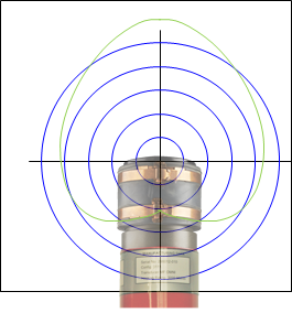
This transducer is designed to direct the majority of its transmit energy and its receive sensitivity in the forward portion of the transducer. On a standard directional transducer, the metal ring at the end is where the acoustic energy dissipates. Ideal for when your target is operating in deep water or directly below your transceiver.
Omni-Directional transducers
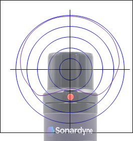
This transducer type is designed to transmit its energy in more of a hemispherical pattern to ensure that maximum coverage is provided allowing for maximum robustness. The acoustic phase centre of this design is central to the rubber boot of the transducer. Ideal for ROV, AUV and diver tracking operating at high elevations or long slant ranges.
With the above in mind, it is important to locate the transducer on the target in such a way as to ensure that there is both no shadowing of the transducer and no destructive interference caused by the reflection of acoustic signals. Think about line of sight, can the transceiver on your surface vessel see the transponder on the target you are tracking? Also, ensure your transponder isn’t mounted near any source of external noise or aeration. For example, avoid placement around ROV thrusters or divers expelled air.
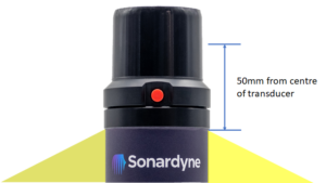
For Omni-Directional transducers, the phase centre of the acoustic transducer should be located 50mm from any structure.
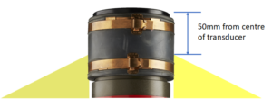
For Directional transducers, the phase centre of the acoustic transducer should be located 50mm from any structure.
The following are general mounting good practices to ensure optimum acoustic performance:
- Transponder mounts should have a 60-degree slope to help prevent reverberation from interfering with the acoustic signals.
- Transponders should be located away from vertical surfaces/obstructions.
- If the use of guard wire over a transducer is planned, then a diameter of <8mm should be used.
- If choosing to use a moulding over the transducer for protection/reduction then an acoustically transparent material should be used and tested to prove the lack of interference.