6G modems make the connection between data and decisions
Two years ago Shell Exploration and Production (Shell E&P) approached Metocean organisation RPS Evans Hamilton Inc to expand the capabilities of their service to measure seabed current profile data at the Walker Ridge area in the Gulf of Mexico.
The challenge
Operations in deep and ultra-deep water (6,000 to 10,000 feet) are challenging for drilling, construction and pipeline installation. These challenges can be made safer and more efficient through a good understanding of subsurface current patterns. For this to be effective, wireless transmission of observations to the surface are essential for instant analysis.
This type of data is usually obtained using acoustic Doppler current profilers (ADCPs) mounted near the surface looking down through the water column. As operational depths increase, a second ADCP, placed on the seabed looking-up, provides the additional data.
The most common approach involves deploying the second ADCP for several months at a time. This is set to log bottom currents at intervals from minutes to hours. While this data is extremely useful for site surveys and planning exploration activities, the delay between collection, instrument recovery, download and analysis, means its usefulness is limited. Particularly when needed for supporting on-site decision making during operations (including complying with government directives). A faster way to retrieve the data collected by the ADCP is needed.
The solution
An acoustic modem directly connected to the ADCP provides a cost-effective and increasingly popular option for providing instant access to the data collected. The modem enables access to the data from almost anywhere in the world.
But not all acoustic modems are made equal. It’s vital to make sure when choosing one for use in an application such as offshore drilling, the signal processing and error correction techniques reliably deliver critical data payloads over long distances and, if needed, through acoustically hostile transmission paths.
RPS Ocean Science identified Sonardyne’s 6G (sixth generation) wireless communications platform as the optimum solution. 6G has an enviable reputation across the region. Today it’s the only acoustic technology to have been proven as a successful monitoring solution during a well containment situation.
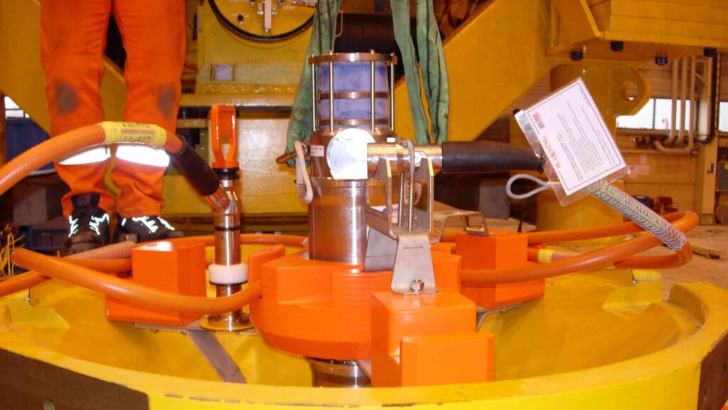
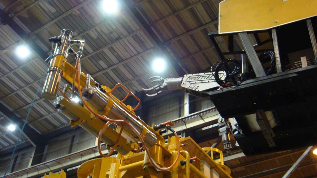
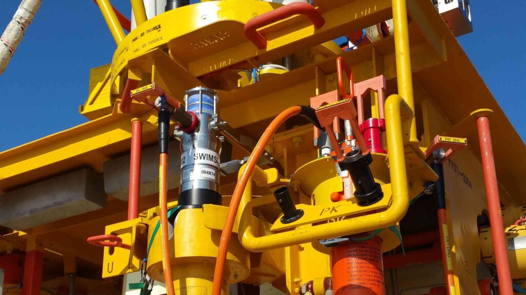
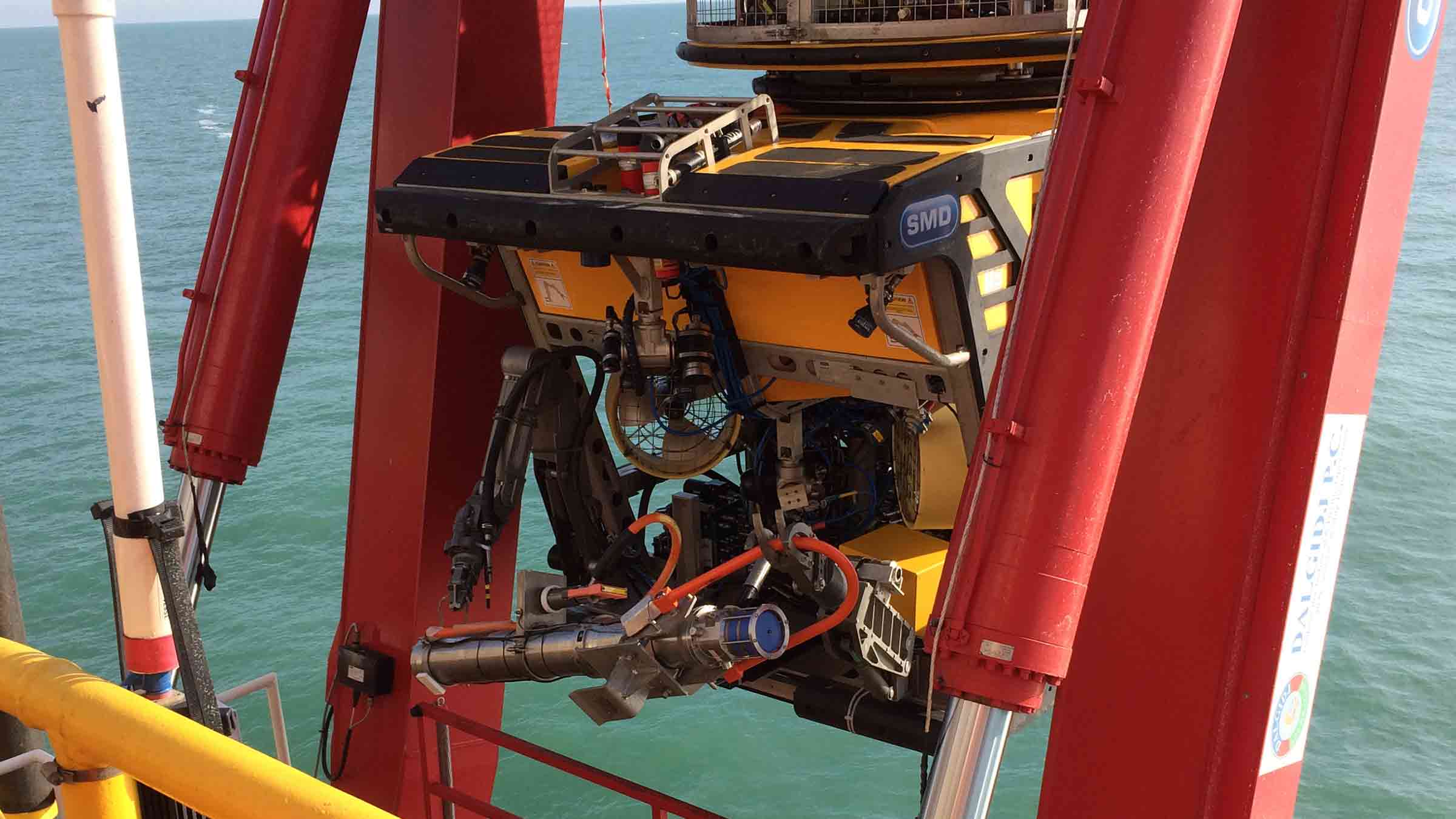
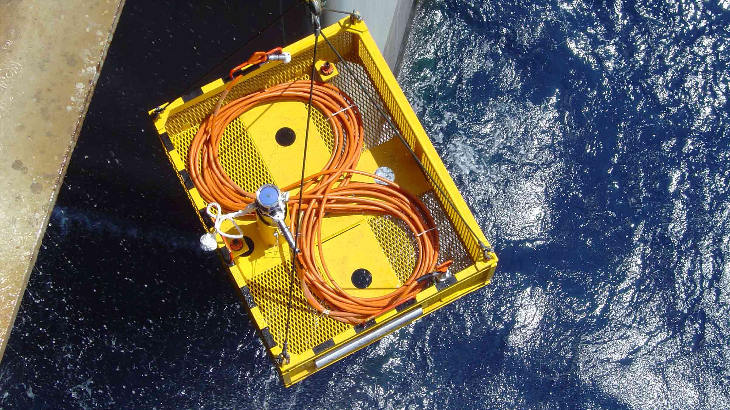
The seabed component of the monitoring system incorporated a Sonardyne Compatt 6 telemetry transponder interfaced with a Teledyne RDI Workhorse 300 kHz ADCP. These were mounted together in a deployment frame. 10,000 feet above, a Sonardyne HPT modem deployed from the rig acted as the surface receiver. It was enclosed within a rugged cage to protect it during deployment and recovery phases, and weighted to prevent drifting in high surface currents.
The HPT was integrated with the data collection system RPS Ocean Science had previously supplied to the rig, this included a 38 kHz ADCP at the surface and load handling system. The Compatt 6G modems and ADCP were deployed by ROV on the seabed at a depth of 9,970 feet, approximately 150 feet away from the rig’s BOP.
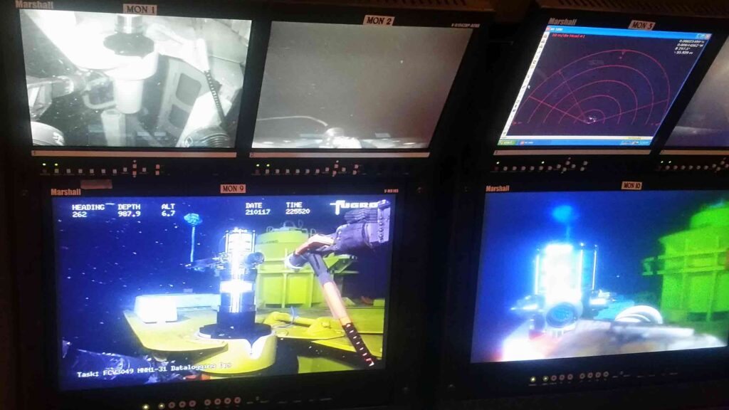
After establishing reliable seabed to surface communications, data collection was initiated. The acquisition system is designed to receive and display data from the surface and bottom ADCPs at 10 minute intervals.
Modem 6
0
m
operating depth
0
bps
acoustic comms
The results
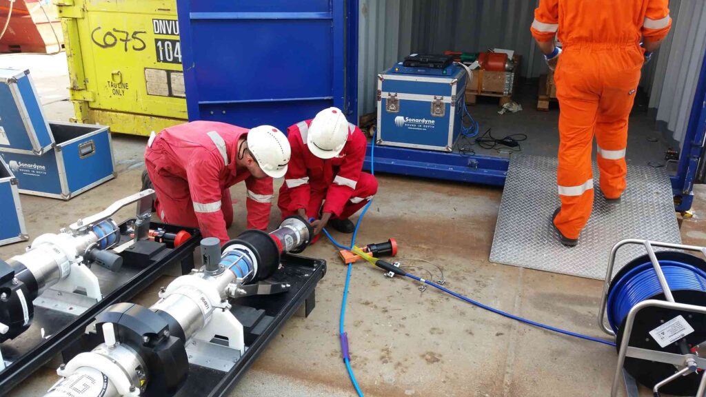
Following initial system deployment, the signal analysis tools built into the Compatt 6 and HPT enabled the bidirectional communications link to be optimised for the local conditions. This resulted in highly reliable and low latency data return rates.
Water velocity profiles were generated from approximately three metres to 100 m off the seabed. The profiles were composed of 50, two metre bins. Data was averaged over 75 seconds at a 1 Hz sample rate. Velocity and direction profiles were processed by the subsurface instrument and transmitted to the rig’s data acquisition system where profiles were displayed, along with the velocity and direction profiles from the surface ADCP, on the platform bridge.
The data has been utilised by the metocean team to support exploration operations in daily advisories as well as providing a unique perspective on potential Topographic Rossby Waves thought to be a common feature in the area. Processed data files were also transmitted to our client’s shore-based server and the National Data Buoy Center (NDBC) in near real-time.
A demonstration of the system’s capability took place during the summer of 2015. Since then, the RPS-Sonardyne solution has proven to offer reliable self-contained operation with long service intervals. The configuration of the upward looking ADCP and Sonardyne 6G digital modem technology perfectly complements conventional near-surface and mid-column current monitoring. It also contributes toward lowering operational risk and increasing the safety of drilling, survey and ROV operations in deep water.
Underpinning the Indian Tsunami early warning system
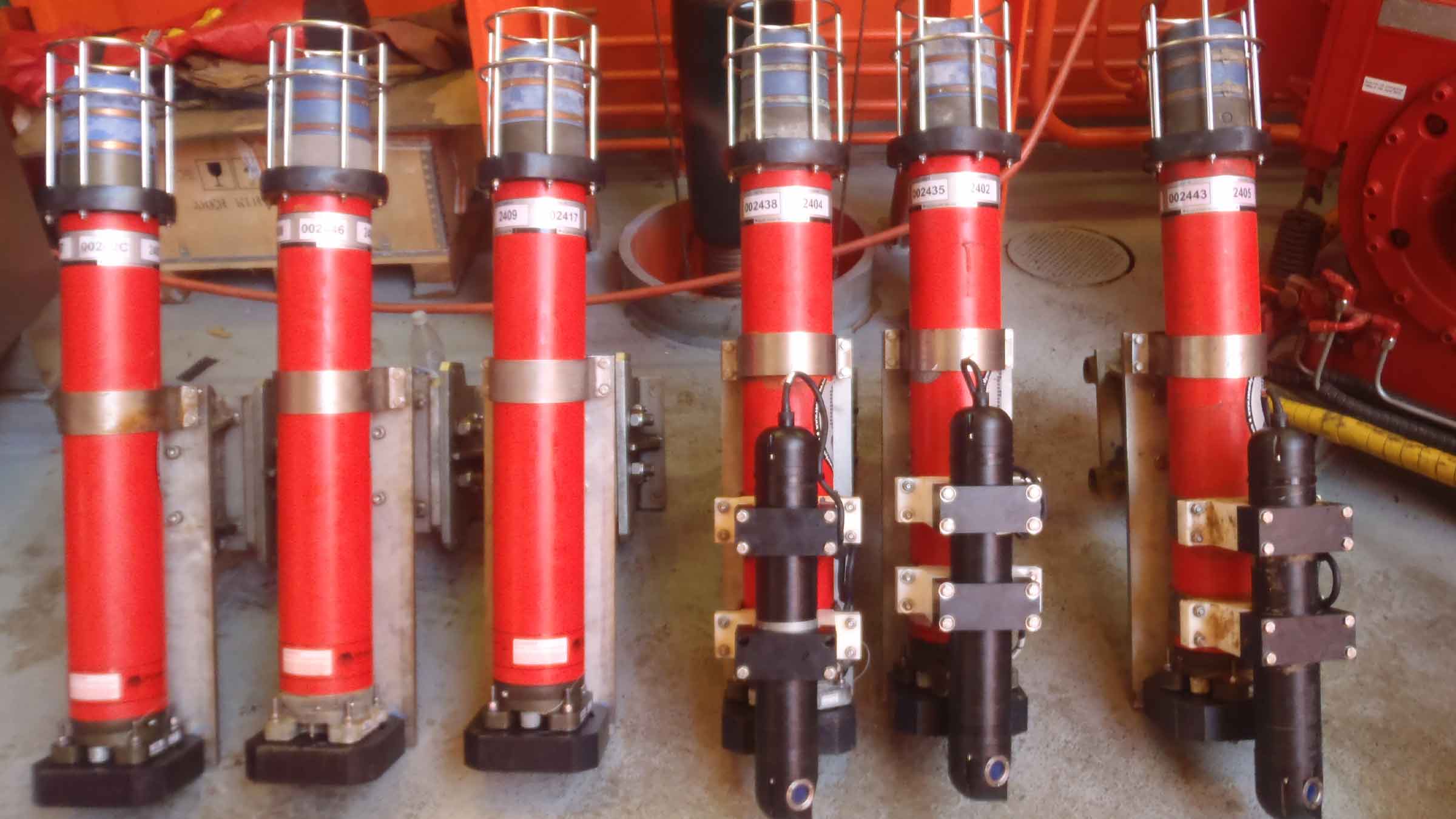
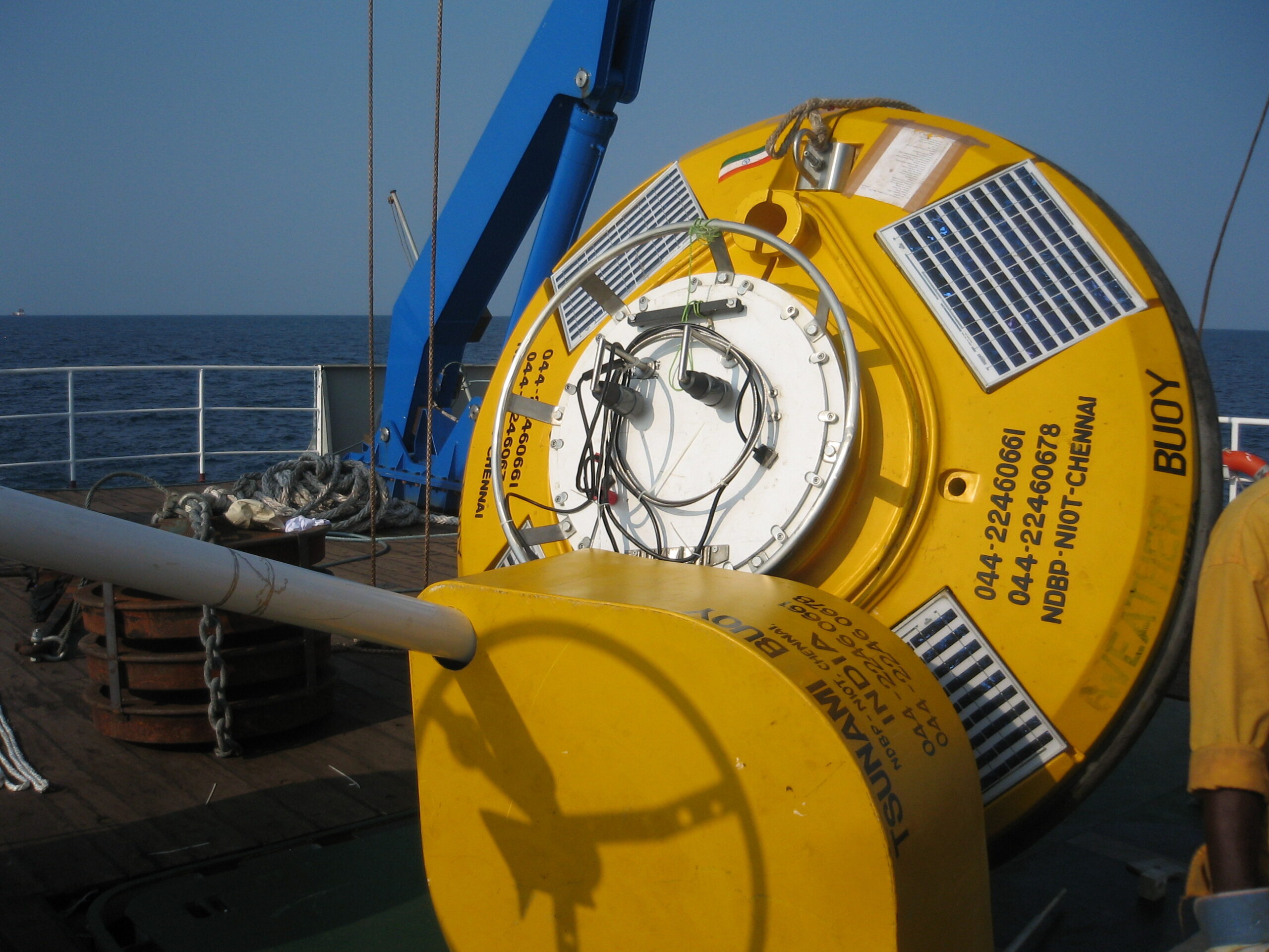
Sonardyne Bottom Pressure Recorders (BPR) have been at the heart of the Indian Tsunami Early Warning System (ITEWS) since its establishment in 2007. Based on Sonardyne’s workhorse Compatt transponder, our BPR instrument was developed in direct response to the devastating 2004 Indian Ocean Tsunami.
The challenge
30% of India’s population (ca. 420 million) live on its 7,500 km long coast and are consequently highly vulnerable to devastating Tsunamis such as the one that occurred on 26th December 2004. This killed over 230,000 people in the Indian Ocean region, with 10,749 confirmed deaths in India and another 5,640 missing. While seismometers are an important component of Tsunami warning, only Bottom Pressure Recorders can detect the passage of an actual Tsunami. Indeed, Tsunami warnings based purely on seismic data have the potential to produce false alarms, which are costly in wasted evacuations and undermine public confidence.
The essential elements of a Tsunami Detection System (TDS) are:
1. The capability to detect a Tsunami – While a Tsunami may arrive at the coast many metres high, in open ocean they pass almost imperceptibly and may only be a few centimetres in height, although this elevation in sea-level can be maintained for as long as 20 minutes.
2. The functionality to provide this detection ashore with sufficient warning time – A Tsunami travels (in ms-1) at roughly the square root of the depth of the water (in m) multiplied by the acceleration due to gravity (9.81ms-1): In short, it travels faster in deeper water, so for example, in 1,000m of water it will be travelling at over 1,100 kmh-1. In India’s case, the Andaman-Sumatra and Makran subduction zones are located within a few hours Tsunami travel time of the Indian coastline
3. High reliability in delivering the detection information ashore – BPRs, as the name implies are deployed on the seabed, so rely on robust telemetry, which has to operate even in poor weather conditions continuously 24/7/365.


The solution
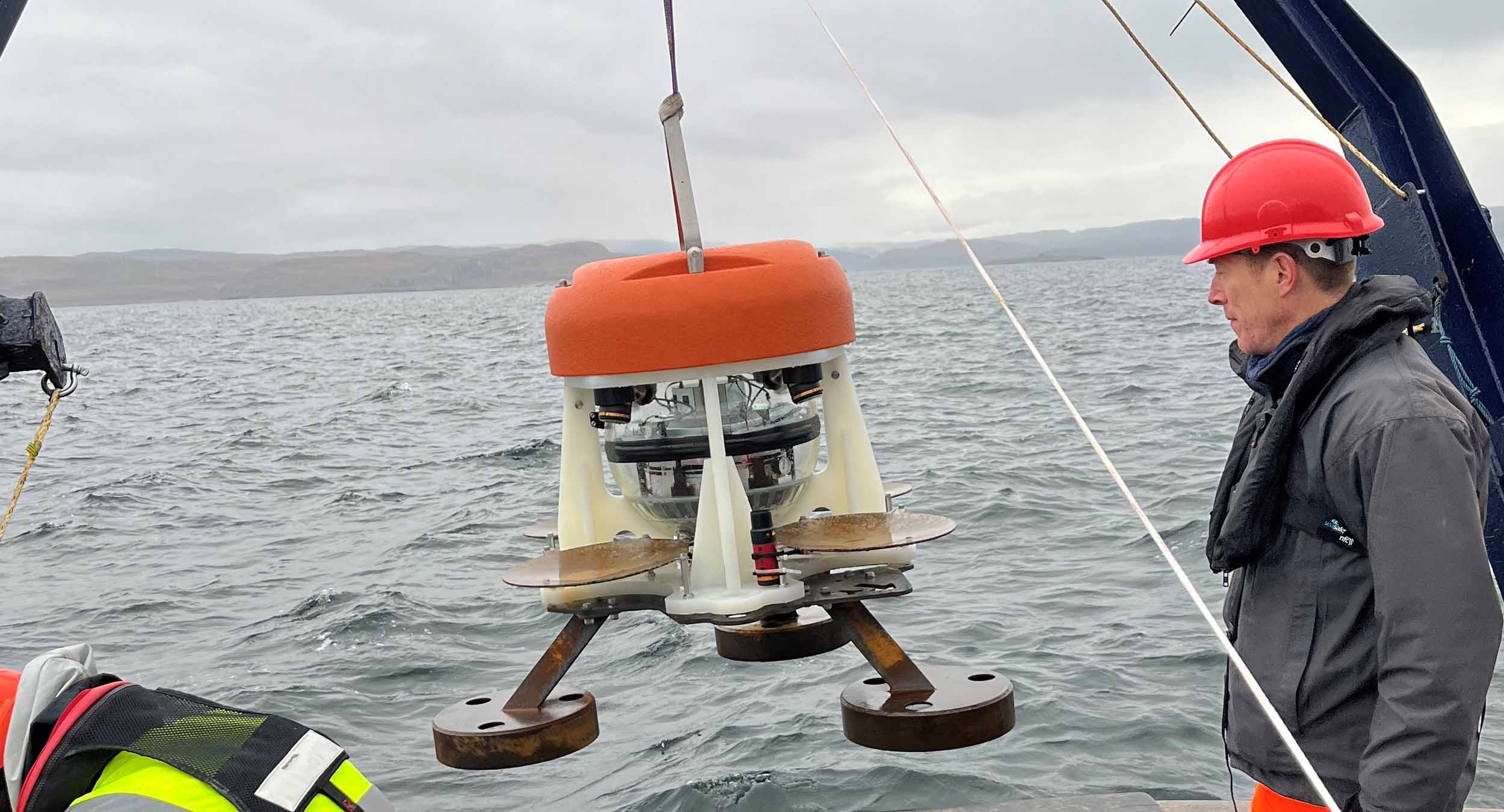
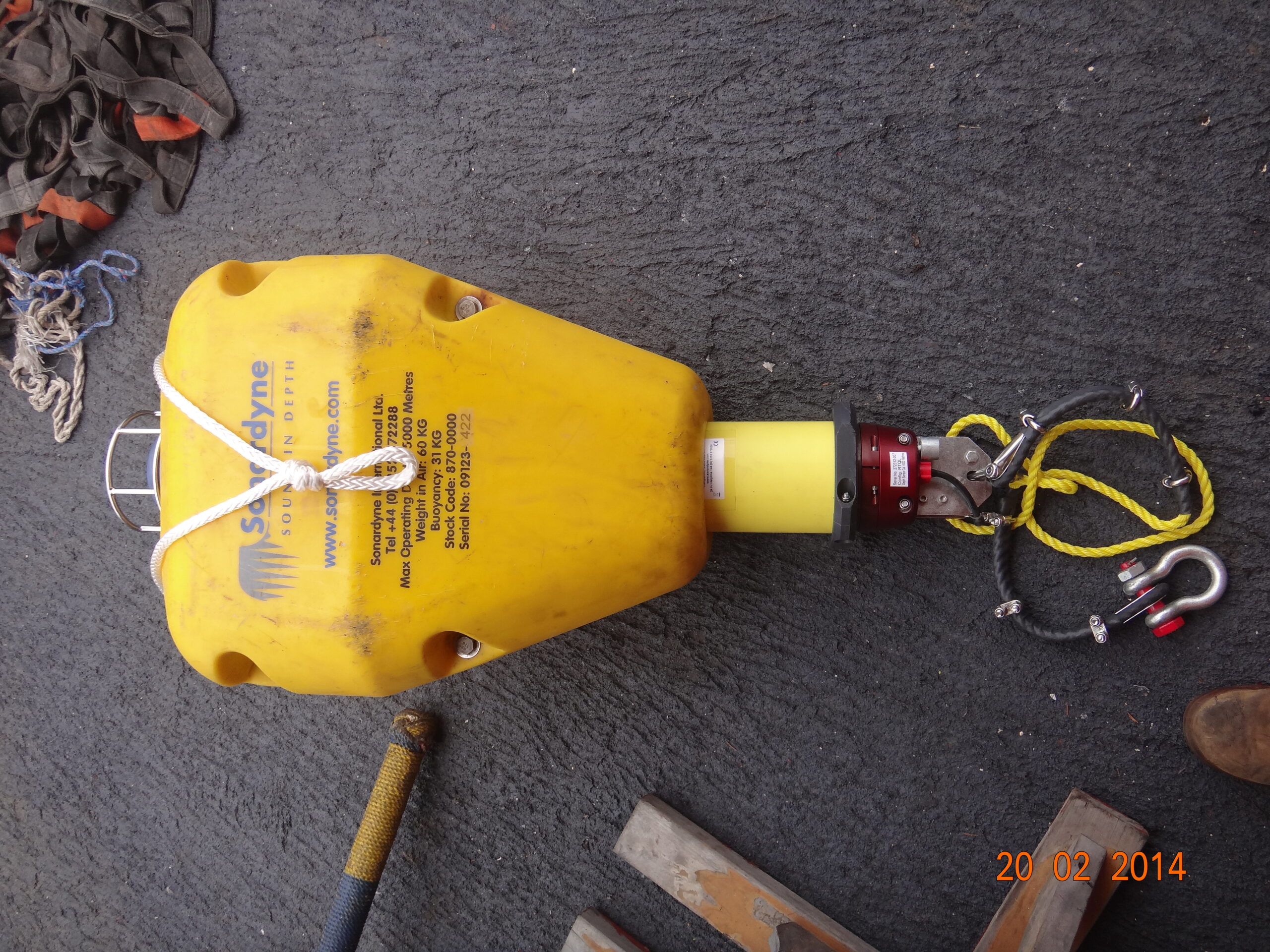
The catastrophic 2004 Indian Ocean Tsunami led Sonardyne’s founder, John Partridge, to initiate development of a variant of the Compatt 5 seabed transponder to detect a Tsunami passing overhead.
With an extensive track record in the oil and gas industry, this instrument was ideal to form the heart of a TDS requiring very high reliability. Nevertheless, integration of a Digiquartz pressure sensor to enable the Compatt 5 as a BPR, required significant development. This particularly involved reduction of the power required for continuous operation on battery power. Similarly, a new transceiver with low quiescent power, capable of long endurance deployment on a surface telemetry buoy, also had to be developed.
Development was so rapid that when India’s National Institute of Ocean Technology (NIOT) in Chennai, started looking for a TDS in 2005, it was ready for competitive field trial. Sonardyne’s solution was subsequently selected in 2006, leading to deployment of operational systems in the Bay of Bengal and Arabian Sea in 2007.
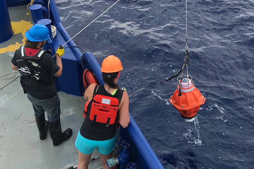
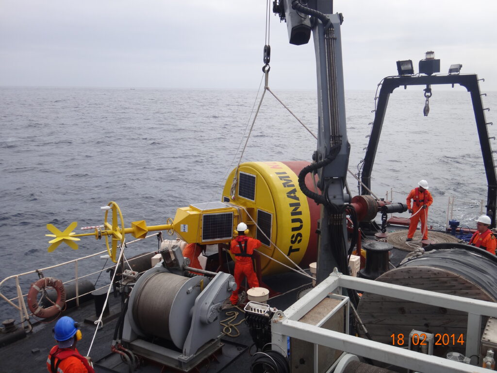
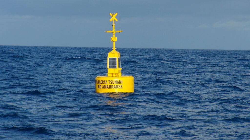
In normal operation the Digiquartz pressure sensor in the BPR continuously measures water pressure and this data is stored every 15 seconds. The pressure data is then acoustically transmitted every hour to the surface, where an acoustically baffled transceiver, mounted beneath a buoy, receives this data. The buoy is linked to NIOT’s Mission Control Centre (MCC) by satellite communications, so that not only can data be transmitted ashore quickly, but also the health of the BPR is remotely monitored and, if necessary, reconfigured.
Embedded in the BPR is the National Oceanic and Atmospheric Administration’s (NOAA) Tsunami detection algorithm, which compares each measurement to the predicted pressure [Figure]. This predicted pressure uses the previous 3-hour history to take account of tide, weather and temperature variation. Should the difference between the two exceed a programmable default threshold of 3 cm for two consecutive samples, the BPR switches into Tsunami Alert Mode, which then initiates a sequence of data transmissions for the next few hours.
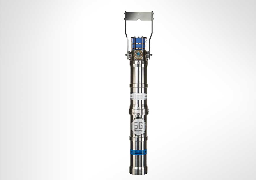
Sonardyne’s Wideband acoustics are central to the functioning of the system, and with the subsequent replacement of the Compatt 5 with Compatt 6, Sonardyne’s latest TDS offering is equipped with the most robust and efficient wideband acoustic telemetry available.
Of India's population
0
%
live on its long coast line
Monitoring
24/7/365
The results
Soon after the first batch of BPRs were deployed, on the 12th September 2007, the system detected its first Tsunami, which was triggered by an 8.2 magnitude event off the coast of Sumatra at 04° 30’ S 101° 18’ E. How the Tsunami generated was tracked across three of the Indian Tsunami Buoys (ITB) is shown in the gallery.
Located between 1,760 – 2,300 km away, all three stations recorded the seismic ground wave arrival between 7 – 12 mins after the event started. Between 2 – 3 hrs later, the wave itself, which was less than 10 cm in height, passed over the three BPRs, indicating that it had travelled at between 740 – 800 km/h over this period.
Today, Sonardyne’s TDS continues to deliver bottom pressure and event data to NIOT, which is responsible for delivering sea-level data to the Indian Tsunami Early Warning Center (ITEWC) at the Indian National Centre for Ocean Information Sciences (INCOIS) in Hyderabad. In 2014, NIOT reported that system data availability had been 98.83%, with a Mean Time Between Failure (MTBF) of 1.62 years, noting that the majority of these failures were due to external impacts, including weather and human interference with the surface buoys, resulting in damage to surface communication and data systems.
Overview
Unleash the power of seamless well monitoring with your Acoustic Data Logger
Experience the power of seamless, long-term well monitoring with our cutting-edge Acoustic Data Logger. Unlock unparalleled insights, optimise your operations, and take your well management to new levels of efficiency and success. Introducing our state-of-the-art Acoustic Data Logger – the ultimate solution for reliable, long-term well monitoring. Engineered to withstand the harshest environments, this versatile device is your key to optimising your operations and unlocking unparalleled insights.
Durable, compatible, configurable, portable
Why Acoustic Data Logger is perfect for your operations
Built on more than 30 years of successful installations, Acoustic Data Loggers provide you with the power to read multiple gauges at predefined intervals, securely store the received information within the unit, then transmit it acoustically through the water column to the surface on-demand.
The current generation includes our 6G and Wideband 2 acoustic technology, allowing large volumes of logged data to be rapidly and accurately retrieved at the surface.
Unmatched longevity for unwavering performance
Say goodbye to frequent maintenance and costly disruptions. Your Acoustic Data Logger can remain deployed for several years without the need for intervention, ensuring your well data is captured with unwavering consistency. They are compatible with Intelligent Well Interface Standardisation (IWIS) and non-IWIS gauge cards from the leading wellbore downhole pressure and temperature gauge manufacturers.
Using normal gauge reading sample rates they can operate for up to three years. Longer deployments or higher sample rates are easily accommodated using external battery packs. All hardware is supplied in corrosion-resistant super duplex stainless steel canisters for very long deployment periods.
ROV portability to a maximum depth of 3,000 m, makes the system ideal for initial well appraisals, where frequent downhole pressure and temperature readings need to be logged over a few weeks. However, the system is equally suitable for long-term deployments where it may remain installed on a wellhead, logging data for several years without intervention.
Suspended or abandoned well monitoring
High-availability acoustic subsea modems are designed for use with third party systems to facilitate the transfer of wellhead or wellbore data to the surface. Our modems can be designed, tested and supplied as part of a third party’s well monitoring solution, including electromagnetic, and through-casing tube technologies to the wellhead or tree-mounted modem.
At a glance
- Perfect for well appraisal campaigns
- ROV-deployable, easy to move between wells
- Can be interfaced to wide range of down hole gauges
- Depth rated to 3,000 m (10,000 feet)
- Harvest data using vessel, rig or ASV


Performance
• Standard depth rating of 3,000 m
• Configurable sample rates from 2 minutes to 5 days
• Weight in water 63 kg
• Acoustic data rate 300–9,000 bps
Design
• Super Duplex Stainless Steel construction
• Integrates into all industry-standard gauge cards
• Fully configurable logging and reporting scheme
• 512 gb internal storage
Connectivity
• ROV mate-able connection
• LMF (14–19kHz) acoustic link
• High speed, spread spectrum acoustic data link
Support
• Comprehensive and flexible training for system operators
• 24-hour support, whenever and wherever you are in the world
• Work side-by-side with our Custom Engineering Team from concept to deployment
• Systems are manufactured and tested before delivery at our world-class in-house facilities
Specifications
| Feature | Type 8195 | |
|---|---|---|
| Acoustic communication | ||
| Operating frequency | LMF (14–19 kHz) | |
| Transducer beam shape | ±30° (directional) ±70° (omni with noise shield) |
|
| Transmit source level (dB re 1 µPa @ 1 m) | >190 dB | |
| Receiver threshold (dB re 1 µPa) | 85–120 dB (7 levels) | |
| Acoustic data | Link | High speed, spread spectrum |
| Transmission rates | 300–9,000 baud (true payload rate variable by telemetry scheme) | |
| Power | ||
| Power | Long life lithium primary cell battery pack | |
| Battery capacity | Single battery pack | 120 Ah @ 14.5 V dc |
| Dual battery pack | 240 Ah @ 14.5 V dc | |
| Battery life | Dependant on interface and logging configuration | |
| Interface card | Supply voltage | 24 V dc ± 4 V |
| Maximum power | 30 W | |
| Communication and interface | ||
| Gauge interface card type | 1x IWIS DHPT Interface Card (dependant on field requirements) | |
| Interface card serial communication format | IWIS RS485 at 9,600 baud, Modbus TCP or Modbus RTU protocol | |
| Interfaces | Serial | 2x RS485/422 – 2x RS232 |
| Analogue | 6x Analogue | |
| Serial communication | Direct serial access to data logger & Gauge Interface Card via the external serial port | |
| Logging and data storage | ||
| Minimum memory capacity | 512 Mb – Industrial SD Card (non-volatile) | |
| Sample rates | Standard | Configurable from 2 minutes to 5 days (dependant on interface) |
| Special | High sample rate operation for user defined durations from 1 minute to 4 days with configurable rates from 5–60 seconds (dependant on interface) | |
| Mechanical | ||
| Mechanical construction | Super duplex stainless steel – UNS32550 | |
| Mechanical design | Sonardyne 6th Generation including inter O-ring test ports | |
| Dimensions (length x diameter) | MF single battery configuration | 1,086 x 199 mm |
| LMF dual battery configuration | 1,348 x 199 mm | |
| External connectors | Gauge interface | 1 x ODI or TRONIC (dependant on field requirements) |
| Serial test port | 1x Subconn MCBH8M 1x Subconn MCBH8F |
|
| Environmental | ||
| Depth rating | 3,000 m (dependant on connector) | |
| Operating temperature | -10 to +55°C | |
| Storage temperature | -25 to +70°C | |
| Design qualification | ISO 13628-6 Level Q1 & Q2 | |
| Options | ||
| ROV handle Type 8195-007 | ROV handle assembly (folding), super duplex stainless steel – UNS32550 | |
| Battery configuration | Single (120 Ah), dual (240 Ah) or triple (360 Ah) |