How can we help?
How to set up Responder Mode
12 May 2022
Utilising responder mode can lead to significant improvements in ranging accuracy and repeatability when operating in noisy environments.
Responder mode is recommended for the following operations
- On acoustically noisy ROVs
- Whenever an electrical trigger signal is available via an umbilical from the ship’s navigation system
- When tracking from a USBL system at < 20° from the horizon
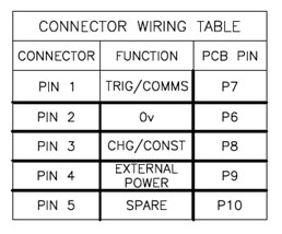
All WSMs have a 6-pin Subconn connector for serial communication and responder triggering. The pin outs are the same for WSM5, 6 and 6+
The 631-7623 Responder card allows for two responder triggers to come from one 5-pin lemo connection. An example of this card can be seen in slot 11 of the below image of an NSH.
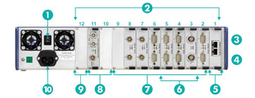
Note: Responder cards can only go in slots 10 and 11 as highlighted by item 8 on the above image.
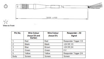
There are various revisions of the 820-3349 responder cable. Care should be taken to identify the pin and corresponding colour to ensure the right connections are made.
Creating a Single Responder Cable
A single responder cable can be manufactured using a 5-pin lemo cable. The table below has been generated with respect to the WSM bulkhead pins and functions.
Creating a Dual Responder Cable
A single 5-pin lemo cable can supply two responder trigger pulses. To perform this, both responders must share the common 0V connection. The table below has been generated with respect a 5-pin lemo connector and its functions.
| WSM 1 Bulkhead | WSM 2 Bulkhead | Lemo Tail | Signal |
| 1 | NC | 1 | Responder Trigger 1 |
| 3 | NC | 2 | +24V Responder 1 |
| NC | 3 | 3 | +24V Responder 2 |
| 2 | 2 | 4 | 0V |
| NC | 1 | 5 | Responder Trigger 2 |
Software Configuration
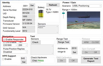
A WSM6+ can be configured using 6G Terminal Lite. Within the setup tab, the user can select to enable responder mode. This will enable to WSM6+ to reply with a wideband reply signal, when configured as a responder.

Prior to deployment this should be checked. Produce a 6G test report as evidence of any pre-deployment checks.
If the version of Ranger2 is V6.00 or greater, only a WSM6+ can be used within the software. As of May 2020, the WSM5 and WSM6 transponder have been deemed obsolete and are no longer supported. Therefore, the guide will continue with the application of a WSM6+ only.
1 A transponder can be added to a Ranger2 system as a responder by navigating to the beacon table.
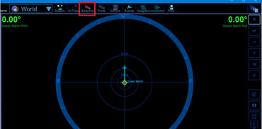
2 Once the beacon table has been opened, click Add.
3 Select WSM6+
4 Add prefix.
5 Select correct address.
6 From the drop-down menu select, responder for interrogation.
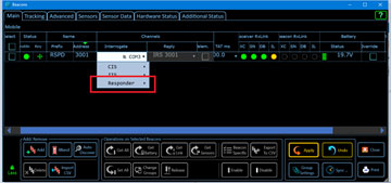
7 Select the relevant NSH port as the responder trigger. This will be the NSH port number and responder number either 1 or 2 depending how you wired your lemo connection.
Perform a desk test and ensure you can hear transponder transmit or “chirp”
A Digital Multimeter (DMM) should be used to ensure the responder umbilical is normally low (0V) and is chirping on a high going trigger pulse. The trigger pulse waveform is required to be a positive going pulse with a pulse width between 5 and 40ms and voltage level between 4 and 24 V.
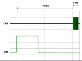
If the responder cable is going through an ROV mux, you should ensure the pin is usually low. If the pin is usually high, this will cause a delay response in the transmit signal and had an adverse effect on tracking.
Contact Support@sonardyne.com for more information.
Looking for more content?
Find more product support in our Knowledgebase
Haven't found what you're looking for?
Then speak to one of our team for expert help


