Sonardyne
Support Centre

A Fetch AZA instrument is mostly in one of two main states, which are (1) Transport Mode; and (2) Seabed Mode. This article describes what these modes are and when they should be used.

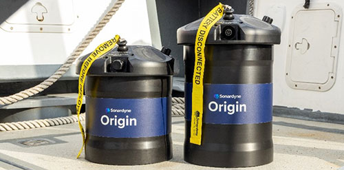
Transport mode is what it says – when the Fetch AZA is delivered from the factory, it will be in transport mode. It should be in this mode whenever the instrument is a) out of the water and b) not actually running.

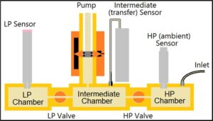
In transport mode, both valves within the AZA mechanism are open and all three pressure sensors are connected to the atmosphere outside the Fetch. This means that the low pressure reference sensor aka the zero pressure sensor will be protected against excess pressure caused by temperature extremes, such as strong sunlight. The Fetch AZA must NEVER be deployed while in transport mode, as the low pressure sensor will be destroyed by the pressure outside the sphere.

In seabed mode, the transfer (aka primary or intermediate) and ambient (high pressure) pressure sensors are both connected to the outside, while the low pressure sensor is sealed behind the low pressure valve. The Fetch AZA MUST be in Seabed Mode when it is deployed.

You can find out more detail on how to set up a Fetch AZA instrument for deployment by watching the video below. Check out the FAQ to find out how to instruct a Fetch AZA to enter these different modes.

Watch: Deck preparation using SAM

When setting up a logging schedule for a Fetch instrument using Subsea Array Manager (SAM) software, there is an option in the log event configurator for different sensors/measurements to set ‘progressive logging’ when adding log events. This article describes what this means and when it should be selected.

The progressive logging setting is only necessary when adding a log event for the AZA measurement of a Fetch AZA instrument. The reason it is good practice to select progressive logging when configuring the logging schedule of the AZA measurement is related to pressure drift patterns.

Analysis of many data sets has shown that pressure sensors tend to drift more when new; after a time the rate of drift slows down until they are essentially stable. This is why it is typical to configure a Fetch AZA to make AZA cycles at an initially frequent rate and then slow down progressively until reaching a much slower final rate, i.e. progressive logging.

When selecting progressive logging, there are other settings that need to be inputted to define what that progressive logging schedule looks like. These settings include ‘increase each log’ and ‘maximum log period’.

As a typical example, you may set ‘increase each log’ to 2.00% and ‘maximum log period’ to 28 days. What this means is that the interval between AZA cycles will increase by 2% with each successive cycle until 28 days are reached and thereafter every 28 days.

Progressive logging is not mandatory; if not selected, the AZA cycle will simply take place at fixed intervals. If you are applying short intervals, consider the draw on the battery and how this will affect the overall endurance of the instrument.

You can find out more detail on how to set up a logging schedule for Fetch AZA using SAM by watching the video below.

Watch: Deck preparation using SAM

The AZA (Ambient-Zero-Ambient) mechanism inside a Fetch AZA instrument is an intelligent device that appears as a single sensor within the Fetch. Although appearing as a simple single sensor, the AZA mechanism actually coordinates measurements from three separate pressure sensors, an electrically-operated pump and a pair of valves in order to calibrate the sensors, with a whole AZA cycle taking many minutes (dependent on water depth). So what are the pressure sensors involved?

The Sonardyne AZA mechanism is one closed reservoir, split into three chambers by valves, with each chamber housing a pressure sensor:

1. The high pressure chamber is fitted with an ambient, high pressure sensor, which is typically a Keller or Presens sensor.
2. The intermediate chamber is fitted with the primary sensor, also known as the transfer or intermediate sensor. This sensor is always a Paroscientific Digiquartz sensor. The intermediate chamber is also fitted with an electrically-operated pump that is used to control the pressure in the chamber.
3. The low pressure chamber has a low pressure reference sensor also known as the zero pressure sensor, which is typically a Terps sensor.

The measurements from these pressure sensors throughout an AZA cycle ensure the determination and correction of pressure sensor drift.

Want how to learn how these pressure sensors operate together in the Fetch AZA mechanism? Check out our video below and read our white paper.

Watch: Technology focus – Fetch AZA

The Sonardyne Autonomous Monitoring Transponder or AMT and Fetch share similar functions but what’s the difference and what’s the advantage of Fetch over an AMT?

The AMT is very much Fetch’s ‘little sister’.

Both instruments are long endurance subsea logging nodes with an inbuilt acoustic modem to enable data to be accessed remotely and therefore the ideal partner for remote and precise seabed monitoring.

The difference is that Fetch has been designed for very long-term monitoring with a battery life of up to 10 years and more, compared to around five years maximum for the AMT.

Fetch is also more adaptable to your needs with more options to customise your instrument. One such option is the AZA (Ambient-Zero-Ambient) mechanism which eliminates pressure sensor drift via in-situ calibration of the pressure sensor.

Eliminating the pressure sensor drift enables you to detect minute-level vertical changes over long periods of time, revolutionising the capability to monitor seabed subsidence and tectonic activity.

For more information about the Fetch instruments and their capabilities, watch the video below.

Watch: Fetch – family overview

First, let's look at what are SPRINT-Nav and dynamic positioning?

At Sonardyne, we combine our SPRINT INS (inertial navigation system) and Syrinx DVL (doppler velocity logger) alongside a high accuracy pressure sensor, to create the SPRINT-Nav system, a compact all-in-one navigation instrument for underwater and surface vehicles.

Dynamic positioning (DP) is a computer-controlled system which is used to automatically maintain a vessel’s heading and position without relying on the use of mooring lines or anchors. DP systems rely on position reference systems (PRS) feeding into the DP system to monitor the vessels position and react accordingly to maintain a position and heading.

To add robustness to the DP system, different types of PRS’s are used. This ensures that if one PRS is no longer available to the DP, a second or third PRS is always available allowing the vessel to continue to position itself safely.

The PRS’s must use at least two differing technology types to prevent a common mode failure. An example of this is GNSS (Global Navigation Satellite System) outages caused by environmental factors: the vessel will need another PRS that can continue to provide a robust position to the DP during these periods, for example SPRINT-Nav DP.

What is SPRINT-Nav DP?

SPRINT-Nav DP is a shallow water DP reference system which operates without needing a GNSS signal. When using SPRINT-Nav DP, there is also no need to deploy any other equipment such as transponders and reflectors as the system uses the seabed for reference.

This increases the operational footprint of the vessel which until now has been limited in range, or weather conditions using existing sensors. Once the system has been given an initial starting position, it will measure its position change from this location, outputting a real-world position to the DP system.

When used independently, INS is an accurate reference for a short period of time, however, it is likely to drift over time if there is no aiding interfaced – combining DVL with INS helps to prevent this.

The use of Sonardyne’s Syrinx DVL provides ultra-tight coupling of the DVL and INS data allowing for increased robustness and error management making the system ideal for DP operations.

We were the first to market a hybrid acoustic-inertial family of products for a variety of subsea applications and SPRINT-Nav now has a proven track record in subsea navigation.

Our SPRINT-Nav family of all-in-one DVL-INS instruments has provided reliable navigation for ROVs, AUVs and USVs for more than a decade. It is known for its performance and is installed on hundreds of platforms.

Not only is SPRINT-Nav independent from GNSS, but it also has high accuracy and position update rate, comparable to GNSS.

Watch: What is SPRINT Nav DP?

Although it has an acoustic modem, Origin 600 is still highly suitable for use in cabled operations. In fact, the acoustic modem provides a reassuring backup for these types of operations, making the Origin 600 a desirable choice whether your operation is cabled or not.

To use your Origin 600 ADCP in a cabled deployment, you will need to supply voltage in the range 18-48 V. This needs to be 18-48V at the ADCP itself (not just at the source) to ensure Origin 600 will draw power from this source without draining the internal battery. The supply voltage will drop further with longer cables. Although it varies, as a rule of thumb a typical power cable of length 50 m will drop 2.8 V. Therefore, the supply voltage must provide 18 V plus 2.8 V per every 50 m of cable to the ADCP. If the deployment requires acoustic communications, this will draw more power, and the source voltage should be raised accordingly.

There are several advantages to using the Origin 600 in a cabled deployment. These include the ability to:


  • Strem live data at full resolution (PD0, A-gram & B-gram) in real time off the device and receive instantaneous water column insights
  • Stream data directly into Origin viewer to view in real time
  • Download all log files prior to recovery
  • Reprogram the ADCP / reconfigure the schedule(s) while the ADCP is deployed
  • Upload new Edge applications while the ADCP is deployed
  • Provide battery backup – in the event of a cable failure, the ADCP will automatically switch to using its internal battery and continue collecting data
  • Provide a backup for real time data

Origin 600 takes its time and date information from the PC it was most recently connected to.

Both Origin Portal and Origin Topside have a button on the settings page to synchronise the ADCP’s internal clock to your PC’s clock.

To set or update the time and date information on your ADCP first make sure your laptop is connected to the internet and synced to UTC, then connect to the ADCP via Origin Portal or Origin Topside and under the ‘Time’ section of the settings page, click ‘Sync to PC’. Origin Topside will notify the ADCP of the current UTC and the ADCP will modify its clock accordingly. If your PC is set to local time, the ADCP will still convert the time to UTC so that your data is always timestamped in UTC.

We recommend that you update the ADCP’s internal clock at the start of each deployment, and then every 6 months or so for long deployments to avoid clock drift over time.

To enable Edge processing on an Origin ADCP, a license must be purchased separately. The licence can then be uploaded to Origin via Origin Portal.

To get an Edge licence, first open Origin Portal on the device you want to generate an Edge licence for. To do this:

  1. Connect the ADCP Breakout Box (8382-024-01) to the Origin unit.
  2. Connect the Breakout box to a PC via Ethernet.
  3. Power the Origin by removing the battery disconnect plug.
  4. Open the Origin Portal UI (at 192.168.179.20) on a web browser and navigate to the ‘Help’ page found by clicking the Question Mark (?) tile. If the system already holds a licence, the information in the ‘Features’ section will look the same as shown below. If there is not a licence on the system, this will be empty.

To generate a licence request, simply click the ‘Generate licence request’ button in the ‘Features’ section. This will prompt you to download a file request called ‘LicenceRequest.bin’. Send this file to Sonardyne ([email protected]) along with a note saying how long you would like the licence to be valid for. We will then generate the licence and send it back to you.

When you have the licence file from us, go back into Origin Portal, navigate to the help page again and click ‘Browse’ in the ‘Features’ section. Select the downloaded licence and click upload to upload the licence.

The information in the ‘Features’ section should update to show the licence information and indicate if it is active.

If you have any problems with any of these steps, please reach out and we will be happy to assist.

Contact [email protected] for more information.

The Origin 600 is delivered in a transit case alongside the components that form the Origin 600 system kit.

The Origin 600 system kit is made up of the Origin 600 ADCP itself, a fast charge power block, a Power-over-Ethernet injector, and a breakout box and wet cable. You will also receive a Sonardyne transducer cleaning tool.

  • Origin 600: The Origin 600 is the main component of the system kit
  • Fast charge power block: The fast charge power block allows the Origin 600 internal battery to be recharged. It consists of a cable that connects to a fast-charge port on the Origin 600 endcap, a power block, and a ‘kettle lead’ cable that connects the power block to mains power.
  • Power-over-Ethernet injector: Origin can be powered using Power-over-Ethernet (PoE). This is enabled using a PoE injector
  • Breakout box and wet cable: This is a short cable tail that connects to the communications and power port on Origin and is used to connect power, Ethernet, and serial port communications to the ADCP. This cable is for configuring/powering the device above water and is not intended for use in subsea deployments.
Two ADCP instruments on a back deck

PD0 is a binary industry standard data format that describes the velocity profile as a function of depth, along with other parameters (such as backscatter intensity), derived metrics, and metadata. The PD0 record contains data for all beams – for example, one PD0 record contains data for all five Origin 600 beams.

PD0 is a flexible, self-describing data format. It consists of a fixed-length header of 6 bytes, followed by Nx2 bytes which describe the byte-offset of the N sections present in each PD0 ‘ensemble’. Each of the N sections contains a 16-bit unsigned integer which describes a unique identifier for the contents of each section. The PD0 record finishes with a 2-byte reserved field followed by a 2-byte checksum.

  • PD0 water velocities are always logged in beam frame
  • Origin always logs PD0 format data to disk
  • All PD0 files are identified by a ‘.pd0’ extension

Contact [email protected] for more information