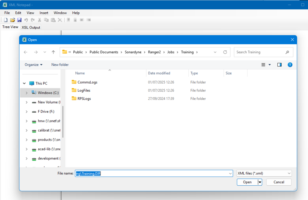
In XML Notepad 2007, open the DJF from the main window:
When loaded it will be seen in the Tree View tab ….
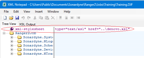
Confirm that the xml-stylesheet is correct as above …. If you’re not loading the DJF in the standard Ranger2 jobs folder location:
C:\Users\Public\Documents\Sonardyne\Ranger2\Jobs\<JobName>\JobName.djf
then it won’t find the denovo.xsl file found at either:
C:\Users\Public\Documents\Sonardyne\Ranger2\Jobs
or
C:\Users\Public\Documents\Sonardyne\Marksman\Jobs
with the link is using a relative path in the href.
Therefore if you’re not loading it in the job folder location, you will need the change the xml-stylesheet value to:-
type=”text/xsl” href=”C:\Users\Public\Documents\Sonardyne\Ranger2\Jobs\denovo.xsl”
so that it can find the xsl file.
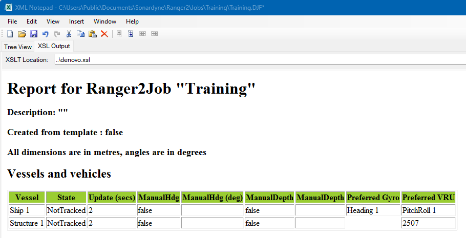
As long as the xsl file is found, then when you select the XSL Output tab, you should see the following:
You can also change the xsl file location, from the XSL Output tab, however you need to select the XSL file found at “C:\Users\Public\Documents\Sonardyne\Ranger2\Jobs\denovo.xsl”, and not the DJF as you’ve tried to do in your screenshot.
Notepad can be downloaded from here
This procedure describes the procedure for changing your Micro-Ranger 2 IP address.
The recommended steps are:
- Change the MRT IP address
- Change the ESH IP address
- Change the PC IP address
- Change the Micro-Ranger 2 ESH and MRT address
Change the MRT IP address
Open 6G Terminal Lite.
Confirm the ESH is connected.

Select “Connect” and “Network Discover TCP”.

Select “MRT TCVR” to connect to the MRT. The fields on the 6G Setup page should be populated if connected.

Select the “Manual Commands” tab.

Enter command Ethernet IP address you want to change the MRT.
- This example is 192.168.1.120 and the syntax is ETH:IPxxx.xxx.xxx.xxx.
- The example command is ETH:IP192.168.1.120

If the manual command is accepted the unit will return the IP address entered and you will now lose connection to the MRT.

Exit 6G Terminal Lite.
Change the ESH IP Address
Refer to Section 5.4.2 in the ESH user manual.
- This example IP address is: 192.168.1.80
Change the PC IP Address
Change the Ethernet connection TCP/IPv4 to the same family.
- This example IP address is: 192.168.1.100
Change the Mini Ranger 2 ESH and MRT IP Address
Start Mini Ranger 2. The ESH and MRT will not initially connect.
Click “System > Setup” and then click “ESH”.

Change the ESH IP address.
- This example 192.168.1.80
The address will be highlighted yellow until you click “Apply”.
Click “Mobile Objects > Ship > Transceiver 1”.

Change the “Transmit IP Address” to the same address as using in the 6G Terminal Lite.
- This example 192.168.1.120
The address will be highlighted in yellow until you click “Apply”.
The ESH and MRT should now connect, and all connections are saved.
Contact [email protected] for more information.
This procedure describes the procedure for changing your Mini-Ranger 2 IP address.
The recommended steps are:
- Change the HPT IP address
- Change the ESH IP address
- Change the PC IP address
- Change the Mini-Ranger 2 ESH and HPT address
Change the HPT IP address
Open 6G Terminal Lite.
Confirm the ESH is connected.
Select “Connect” and “Network Discover TCP”.
Select “HPT 8142” to connect to the HPT. The fields on the 6G Setup page should be populated if connected.
Select the “Manual Commands” tab.
Enter command Ethernet IP address you want to change the HPT.
- This example is 192.168.1.120 and the syntax is ETH:IPxxx.xxx.xxx.xxx
- The example command is ETH:IP192.168.1.120
If the manual command is accepted the unit will return the IP address entered and you will now lose connection to the HPT.
Exit 6G Terminal Lite.
Change the ESH IP Address
Refer to Section 5.4.2 in the ESH user manual.
- This example IP address is: 192.168.1.80
Change the PC IP Address
Change the Ethernet connection TCP/IPv4 to the same family.
- This example IP address is: 192.168.1.100
Change the Mini Ranger 2 ESH and HPT IP Address
Start Mini Ranger 2. The ESH and HPT will not initially connect.
Click “System > Setup” and then click “ESH”.
Change the ESH IP address.
- This example 192.168.1.80
The address will be highlighted yellow until you click “Apply”.
Click “Mobile Objects > Ship > Transceiver 1”.
Change the “Transmit IP Address” to the same address as using in the 6G Terminal Lite
- This example 192.168.1.120
The address will be highlighted in yellow until you click “Apply”.
The ESH and HPT should now connect, and all connections are saved.
Contact [email protected] for more information.
This describes the offsets to be entered for transceiver and Lodestar when configured for Optimised USBL in Ranger 2 or Marksman software, when using a standard-length Type 7950 Deployment Machine.
This document assumes that the Type 7950-400 Lodestar mounting bracket (part no: 875-2488) is used, shown in blue in the sketch below, and mounted to the guide plate on top of the pole.

Dimensions of a standard Type 7950 Deployment Machine are shown below.

However, to calculate Lodestar to transceiver height offsets, further details are required.
| Item | Height |
| Deployment Pole (Standard) | 4590 mm |
| Transceiver Insulation Flange | 10 mm |
| Lodestar Mounting Bracket thickness | 6 mm |
| Guide Plate thickness | 10 mm |
| TOTAL | 4616 mm |
Typically, two types of transceiver are fitted to the Deployment Pole:
- Type 8142-000-01 HPT 5000
- Type 8142-000-02 HPT 7000

| Transceiver | Height |
| Type 8142-000-01 HPT 5000 | 322 mm |
| Type 8142-000-02 HPT 7000 | 391 mm |
The Lodestar has a centre-of-axis point, and this should be used as its height offset.
Contact [email protected] for more information.
To enable flexibility of use of Sonardyne INS and LBL systems, Fusion 2 software has been designed to be modular.
This allows equipment spreads to be purchased at their base functionality and upgraded only if the offshore project requires it. This means you only pay for added functionality when you need it. This is achieved with the use of hardware dongles that the user must attach to the system to provide the functionality required.
SPRINT(Nav) position aided
If you want to use a SPRINT(Nav) using position aiding (USBL aiding for example), you plug in the Fusion 2 INS dongle supplied with the SPRINT(Nav) unit. If you have an old SPRINT software dongle, it can be upgraded for free to Fusion 2 INS.
SPRINT(Nav) range aided / sparse LBL / SLAM
If you want to use a SPRINT(Nav) using range aiding (sparse) including SLAM capability, you must plug in the Fusion 2 INS dongle supplied with the SPRINT(Nav) unit. The owner of the dongle must have paid for range aiding (SPRINT LBL RANGE AIDING SPARSE UPGRADE) which will have set the dongle to enable Fusion 2 INS for both position aided, and range aiding (sparse).
Full (standard) LBL
If you want to do full LBL i.e., same as what you would do with Fusion 1 (baseline calibrations, structure tracking, mobile Compatt tracking, etc), you must plug in a Fusion 2 LBL dongle. Fusion 1 LBL dongles can be upgraded to Fusion 2 LBL providing the dongle owner has paid for a Fusion 2 LBL software upgrade licence.
Running both INS and full LBL simultaneously
If you want to run both Fusion 2 INS (position and/or range aided), and full LBL from a single computer, you must plug both the SPRINT(Nav) dongle programmed for what you need, and the Fusion 2 LBL dongle, into the computer at the same time.
Contact [email protected] for more information.
Utilising responder mode can lead to significant improvements in ranging accuracy and repeatability when operating in noisy environments.
Responder mode is recommended for the following operations
- On acoustically noisy ROVs
- Whenever an electrical trigger signal is available via an umbilical from the ship’s navigation system
- When tracking from a USBL system at < 20° from the horizon
All WSMs have a 6-pin Subconn connector for serial communication and responder triggering. The pin outs are the same for WSM5, 6 and 6+

The 631-7623 Responder card allows for two responder triggers to come from one 5-pin lemo connection. An example of this card can be seen in slot 11 of the below image of an NSH.

Note: Responder cards can only go in slots 10 and 11 as highlighted by item 8 on the above image.
There are various revisions of the 820-3349 responder cable. Care should be taken to identify the pin and corresponding colour to ensure the right connections are made.

Creating a Single Responder Cable
A single responder cable can be manufactured using a 5-pin lemo cable. The table below has been generated with respect to the WSM bulkhead pins and functions.
Creating a Dual Responder Cable
A single 5-pin lemo cable can supply two responder trigger pulses. To perform this, both responders must share the common 0V connection. The table below has been generated with respect a 5-pin lemo connector and its functions.
| WSM 1 Bulkhead | WSM 2 Bulkhead | Lemo Tail | Signal |
| 1 | NC | 1 | Responder Trigger 1 |
| 3 | NC | 2 | +24V Responder 1 |
| NC | 3 | 3 | +24V Responder 2 |
| 2 | 2 | 4 | 0V |
| NC | 1 | 5 | Responder Trigger 2 |
Software Configuration
A WSM6+ can be configured using 6G Terminal Lite. Within the setup tab, the user can select to enable responder mode. This will enable to WSM6+ to reply with a wideband reply signal, when configured as a responder.

Prior to deployment this should be checked. Produce a 6G test report as evidence of any pre-deployment checks.

If the version of Ranger2 is V6.00 or greater, only a WSM6+ can be used within the software. As of May 2020, the WSM5 and WSM6 transponder have been deemed obsolete and are no longer supported. Therefore, the guide will continue with the application of a WSM6+ only.
1 A transponder can be added to a Ranger2 system as a responder by navigating to the beacon table.

2 Once the beacon table has been opened, click Add.
3 Select WSM6+
4 Add prefix.
5 Select correct address.
6 From the drop-down menu select, responder for interrogation.

7 Select the relevant NSH port as the responder trigger. This will be the NSH port number and responder number either 1 or 2 depending how you wired your lemo connection.
Perform a desk test and ensure you can hear transponder transmit or “chirp”
A Digital Multimeter (DMM) should be used to ensure the responder umbilical is normally low (0V) and is chirping on a high going trigger pulse. The trigger pulse waveform is required to be a positive going pulse with a pulse width between 5 and 40ms and voltage level between 4 and 24 V.

If the responder cable is going through an ROV mux, you should ensure the pin is usually low. If the pin is usually high, this will cause a delay response in the transmit signal and had an adverse effect on tracking.
Contact [email protected] for more information.
This procedure can be used to test the MRT operation prior to deployment on operation.
1 Confirm your PC is connected to the ESH and ESH is connected to the MRT. Make sure the ESH is on, system/TCVR 48V are on and TCVR TX/RX lights are flashing.
2 Run 6G Terminal Lite software program. Confirm the “ESH Connected” indicator is green.

3 Select Connect button and select “Network Discover TCP” or “Network Discover UDP” and select the MRT TCVR.

4 The MRT will now be connected and the 6G Set Up tab will be populated.

5 Select the Sensor button and confirm the PASS.

6 You can now Generate Test Report by selecting the button and saving this on the PC.
The tests are to confirm the HPT operation
1 Exit all other software programs including Mini Ranger 2.
2 Confirm the PC to ESH and ESH to Transceiver connections.
3 Open the 6G Terminal Lite Make sure that the ESH is properly connected as shown below before proceeding.

4 Click on Connect and choose NETWORK DISCOVER-UDP and then click The device connected to the Ethernet port will be discovered as shown below. Click Connect to the device (HPT 2000 or HPT 3000).

5 Make sure that the transceiver is connected successfully. Under the Test section, please click on Check Sensors and Check Hardware. Click on Generate Test Report -> a pdf format 6G Test Report will be generated. Please save this file.

6 Go to the “Manual Commands” tab.

7 Then, click on Test, and select Bench Test (HPT Only).

8 New window will appear – HPT Bench and Tank Test. Click on Get Serial Number From HPT. Please check if the transceiver serial number is correct.

9 Click on Test Coms with HPT.

10 Now, click on Perform Test. HPT bench test will start. You can hear the Transmission (ping sounds) coming from the HPT. Click Yes.

11 The software will now measure the average noise in DB’s. You may see RED (failed) average noise measurements due to noise spikes. Please continue testing by pressing “No”.

12 Bench test will continue and will proceed with the Admittance Test. New window will appear – Admittance Measurement Tool. A pop-up message will appear once the admittance test is completed. Click Yes.

13 Save the results and put .csv as file extension.

14 Capture the Admittance Measurement Tool and save it. You can see some RED, AMBER or GREEN readings. These are still subject for UK engineer’s review. Close this window once you save the snapshot.

15 Window will return to HPT Bench and Tank Test. Click on Yes.

16 Capture the HPT Bench and Tank Test window and save it. Results are still subject for UK engineer’s review. Close the window. Click on Disconnect from the main page 6G Terminal Lite software. You can now exit the software.

17 Commslog will be automatically saved in C:\temp.

Please send the following to Sonardyne for review:
- 6G Test Report
- Commslog
- csv
- Snapshot of the Admittance Measurement Tool results
How to complete a 6G Terminal Lite Range Test
Equipment Required
PC with the 6G Terminal Lite test program installed
Serial Cable for the specific beacon under test
2 6G beacons (1 x serially connected beacon and 1 x acoustic test beacon)
Procedure
1 Connect the beacon serial cable to the beacon and the PC’s communication port. My example below is a AvTrak6 (serially connected) and Nano (acoustic test beacon).

2 Start 6G Terminal Lite and confirm communication with the beacon.

3 Make sure the Power/Gain settings is set to In Air Testing.

4 Select the Set button in the Range Test box.

5 Select the beacon address that will be acoustically interrogated.

6 Select OK.

7 Now select the Range Test button. You should hear the beacon connected to 6G Terminal Lite transmit an interrogation signal to the acoustic test beacon and hear a reply signal from the acoustic test beacon. The result will be displayed.

8 If the test fails:
a Confirm the acoustic beacon power and gains settings are set to “In Air Testing”.
b Adjust the distance between the beacons.
c Confirm you can hear the interrogate and reply to signals
d Try an alternative beacon or beacons.
When installing/integrating a SPRINT-Nav onto a vehicle, there are many factors to consider/plan to ensure the system is operational and performs to the required specification.
Installation location
SPRINT-Nav can be installed at any convenient location on the vehicle. However, to gain optimal performance from the system, identify a location to install the SPRINT-Nav that conforms as closely as possible to the following criteria:
- The location must not be subject to excessive vibration or impulse shock.
- The location must not exceed the environmental limits for temperature (operating temperature -5 to 50°C / storage temperature -25 to 55°C).
- The location must provide a mounting surface that is of sufficient strength to support the weight of the SPRINT-Nav safely and without flexing.
- The location must provide access for power and communication connections.
- There must be sufficient space to allow easy access to install the SPRINT-Nav.
- Do not store tools, equipment or chemicals where they can damage the SPRINT-Nav or the connection cables.
- Make sure the SPRINT-Nav and its connection cables do not cause an obstruction to personnel operating in the area.
- Do not use a location where the connection cables are likely to suffer damage from mechanical stresses or chemical attack.
- The location must provide line of sight to the seabed for all 4 Syrinx DVL transducers abiding by the clearance levels:
- This includes 15° clearance around the direction that is orthogonal to the transducer face. The transducer face is orientated at 30° azimuth from the vertical (downward) direction, with each beam at a 90° offset in yaw respective to one another, and all beams rotated 45 degrees in yaw from the forward mark.
![]()
-
- The SPRINT-Nav should be mounted at the greatest distance possible away from the seabed. This is to offset the minimum altitude of operation of the SPRINT-Nav of <0.4 m. If the SPRINT-Nav can be mounted 0.4 m or greater above the bottom of the vehicle with clear line of sight, bottom lock should rarely be lost even if the vehicle settles on the seabed.
- The orientation of the SPRINT-Nav is also important and can affect performance in certain scenarios.
- For most operations, the desired orientation is to line up the SPRINT-Nav forward mark (label or machined grove on housing) with the forward heading of the vehicle.
- For following pipelines where altitude measurements above the pipe are very important, the SPRINT-Nav can be rotated by 45 degrees so that beams then face forward, aft, port and starboard rather than inter-cardinal directions. This will result in the forward and aft beams being directed onto the pipe surface. Mounting angles will need to be adjusted appropriately in this instance.
Mounting
The SPRINT-Nav can be installed in any convenient orientation with respect to the vessel’s body frame. Compensate for any misalignment between the SPRINT-Nav and the vessel by carefully measuring the mounting angles and entering them in the SPRINT-Nav system.
The SPRINT-Nav has a set of eight mounting holes (a further four alternative mounting holes are available) on the outer mounting ring of the unit. In addition, there a set of three-dowel alignment holes.

Alignment
The nominal alignment of the SPRINT-Nav to the vehicle frame (FWD and STBD) is engraved on the top endcap.

If it is not possible to mount the SPRINT-Nav within the limits described above for coarse alignment or if you wish to mount the SPRINT-Nav at other angles with respect to the reference axes on the vessel, ROV or platform, the mounting angles must be measured and configured.
For the SPRINT-Nav to provide accurate attitude and positions with respect to the vehicles reference frame, any misalignment between the SPRINT-Nav and vehicle reference frame must be corrected by determining and applying mounting angles in the SPRINT-Nav system.
SPRINT-Nav Instrument Frame
The SPRINT-Nav system has two types of lever arm and mounting angle measurement references, vehicle frame and instrument frame:
- Vehicle Frame: SPRINT-Nav IMU and sensor lever arms and mounting angles relative to vehicle CRP/Frame (from vehicle CRP/Frame).
- Instrument Frame: sensor lever arms and mounting angles relative to SPRINT-Nav IMU (from measurement point of the sensor assembly).
The instrument frame measurements for the SPRINT-Nav are stored as the factory default within memory, therefore when applying lever arms and mounting angles to the SPRINT-Nav from vehicle CRP/Frame, the user simply applies the new values to the SPRINT-Nav IMU and the system automatically calculates and applies this to the SPRINT-Nav sensors (Syrinx DVL and pressure sensor).
Interfaces and Connections
Prior to installation, SPRINT-Nav system interfaces should be planned to avoid any sensor/system incompatibilities therefore causing delays in the system becoming operational ready.
- Time System: Depending on what navigation requirement is (Dynamic/Construction survey to ROV guidance) will determine what type of time system is required:
- ZDA + 1PPS
- ZDA only
- No Time Sync
- Position Aiding:
- USBL (PSIMSSB of GGA telegram)
- LBL Range Aiding (Fusion 2)
- Sound Velocity
- External sensor feed into the SPRINT-Nav system (Subsea or Topside connection)
- Manual or Derived sound velocity for ROV Guidance
- SPRINT-Nav output messages
- Survey software (EIVA)
- Multibeam
- Vehicle Guidance
Whatever the sensor/systems interfaced with the SPRINT-Nav, ensure all message formats are compatible and available prior to installation to avoid issues and delays.
Cabling
The system cabling must be carefully planned prior to installation to avid issues. Subsea cables can be costly, and time consuming to correct or replace during the installation phase.
Consideration should be given for any serial cable run length, as this could lead to data corruption if the length exceeds RS232/485 limits, particularly the serial connection between the SPRINT-Nav system and the ROV (de) multiplexer is excessive for a 115,200 baud rate RS232 serial link then alternate interfaces should be planned to make sure the data is not corrupted, such as Serial to Ethernet or RS232 to RS422/485 converters. Alternatively, an Ethernet connection to the SPRINT-Nav could be considered. If choosing an Ethernet connection to the SPRINT-Nav, ensure that the vehicle MUX connection support 100Mbit/s.