Sonardyne
Support Centre

The majority of the setup required for a Fetch AZA deployment is done before the instrument even enters the water. BUT once it has been deployed and it is on the seabed, there are a few final stages of setup that MUST be conducted using Subsea Array Manager (SAM) via the acoustic link.

When it comes to setting up a Fetch AZA instrument there are important tasks to be performed via the acoustic link with the instrument when it has been deployed and it is sitting on the seabed:

  1. Enter deployment limits. Go to the AZA tab in SAM and click ‘Advanced’. Enter the maximum deployment depth for your instrument, e.g. 3000, 6000 or 7000 m, click ‘Set Deployment Limits’ and then close. Note: the max deployment depth is limited by the rating of the sensor.
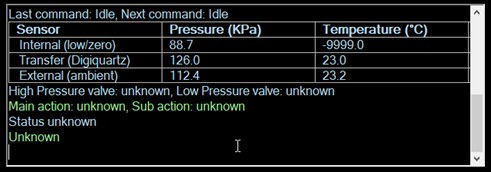
  2. Check pressure readings. Navigate to the AZA tab in SAM and click on ‘Get AZA status’.
  3. Start AZA logging. Simply click ‘Start AZA logging’ in the AZA tab of SAM. A big yellow tick indicates logging was successfully started. As a final check, you can confirm the AZA logging by selecting ‘Check Time and Logging’ in the Check tab.
  4. Retrieve an AZA logged record. It is good practice to retrieve at least one AZA logged record before leaving the site so you can inspect the data to know everything is set up and working. In the SAM ‘Retrieve’ tab, select ‘Get Bookmarks’, then ‘Retrieve’ and then ‘Export’ to generate a CSV file/files for assessment and visualisation of the data.

An important element of the data inspection is confirming AZA pressure readings went to zero (c. 100 kPa) and then back to ambient. Data from other sensors can also be inspected at this stage; for instance, if you are expecting PIES measurements, check PIES returns are measured.

You can find out more detail on how to set up a Fetch AZA instrument for deployment, and how to use the acoustic link with your instrument by watching our videos, including the one below.

Watch: Fetch Acomms and data harvesting

Subsea Array Manager, or SAM, is Sonardyne’s flexible software tool for configuring subsea instruments and for uploading data from them.

SAM is an intelligent application for Microsoft Windows that has been written by Sonardyne to help with the configuration of our many different instruments.

Different instruments offer different selections of sensors, so SAM simplifies the user’s interaction with these instruments by providing menus and panels that are suited to the particular instrument.

In addition to being the software tool for configuring and uploading data from Sonardyne subsea instruments, SAM also can be used to set up arrays of beacons used for positioning subsea assets and distance measurement.

You can find out more about SAM in the video below.

Watch: Fetch deck preparation using SAM

To configure Fetch ready for deployment, Sonardyne Subsea Array Manager (SAM) software must be used. Once this software is installed on your PC, you can use an iWand as a portable transceiver to enable use of SAM to communicate with Fetch. To work as a transceiver, the iWand needs a connection with the computer running SAM, which can be done via USB, or serially via RS232. It is this connection that will enable communication between the SAM software and Fetch.

As a good starting point, if your iWand has one, connect a coax cable with BNC connectors. You have to remove the antenna from the iWand to plug in the connector. You can then clip the antenna onto the Fetch transducer so that you don’t have to hold the iWand up to the transducer all the time.

Alternatively, continuously manually press the iWand antenna onto the Fetch’s transducer to establish the acoustic connection.

Now to connect your iWand to your computer running SAM software. The easiest option to do this is via a USB connection. Simply make the connection using the standard USB-A to USB-B cable, which will charge the iWand at the same time.

To then establish the communications link between SAM and a Fetch instrument via the iWand, select Comms from the main menu at the top of the SAM software window and then click “Comms”. Choose the appropriate COM port for the iWand from the list and click “OK”. To finish, select the Device tab, and click the “Test” button.

You can also connect serially via RS232, perhaps suitable if you’re developing a satellite telemetry system on a buoy or want to interface to a SCADA system.

The iWand has a 9-pin male D connector next to the USB socket, which is wired as a DTE device. This means you should use a null modem cable to connect to the serial port on a computer. A USB-serial adapter can be used if your computer doesn’t have a serial port.

To set up the iWand for this serial connection, select “iWand Setup” from the iWand menu, then “Communications” and choose RS232 (note communications settings will be 9600 baud, 8 data bits and 2 stop bits). With the RS232 setting enabled, you will see a small serial connector icon appear on the top status bar next to the battery level indicator.

The next stage is to make the connection with SAM and this is done in much the same way as was done with the USB connection, by selecting the appropriate COM port and setting a baud rate of 9600.

Note: any of the above methods can also be used to communicate with the iWand 6G Configurator software, or if the iWand is being used as a portable transceiver to communicate with applicable Sonardyne software other than SAM, e.g. 6G Terminal Lite, for checks and setup of Fetch.

You can find out more detail on how to configure a Fetch using SAM software via the iWand by watching the video below.

Watch: Fetch: Deck preparation using SAM

iWand is your ideal and convenient option for basic testing of Fetch before deployment. A key feature of iWand is that once you’ve completed your testing and checks, you can produce a test report for QA purposes and as an audit trail.

To produce an iWand test report, connect the iWand to a PC or laptop (via USB or serial connection) and use the supplied iWand 6G configurator software to create your report.

In the software select your Fetch instrument from either the history or the asset list (traffic light next to the instrument should be indicating green) and then simply click ‘Generate report’. This will produce a two-page document detailing evidence of functionality and settings applied in a PDF format that can be saved and provided to your client or supervisor.

The first page of the report provides information specific to the instrument such as acoustic address, serial numbers and firmware versions etc. It also lists any settings, battery status and sensor details (if fitted) and information of the iWand that gathered the information. If the Fetch instrument has been successfully configured or tested, a large green tick will appear in the top left-hand corner of the first page.

A test report can also be generated when the iWand is connected to other Sonardyne software, such as the 6G Terminal Lite software (click ‘Generate test report’ in the 6G setup tab) or Subsea Array Manager (click ‘PDF report’ in the check tab). We recommend using the iWand 6G configurator software as the ‘go-to’ option for generating a test report after you’ve done your basic testing for Fetch with an iWand.

You can find out more detail on how to run some basic tests for Fetch with an iWand before deployment by watching the video below or reading other FAQ, where you can also find out how to connect an iWand to a PC or laptop via USB or serial connection.

Watch: Fetch: Predeployment checks with iWand

DAS stands for Data Acquisition System, so the DAS time is the time of the internal logger and thus the time allocated to data records collected by a Sonardyne instrument such as Fetch.

Fetch instruments do not have an independent real-time clock, which is why it is so important to set the DAS time every time the instrument is powered up.

Setting the DAS time on a Fetch instrument is simple via Subsea Array Manager (SAM) software, but note that it will be in UTC/GMT.

You can find out more detail on how to set the DAS time using SAM by watching the video below.

Watch: Fetch deck preparation using SAM

When setting the AZA logging schedule for a Fetch AZA in Subsea Array Manager (SAM) it is essential that logging for AZA is configured to start after the instrument has reached the seabed. This article details why this is important.

When selecting the start time of AZA logging during the Fetch AZA configuration process in SAM, you need to allow sufficient time for the instrument to reach the seabed before the logging cycle begins.

The start time must be set sufficiently in the future to allow time to deploy and to send the command to start the logging for both sensors and the AZA cycle.

This is so that the first AZA cycle is not instigated when experiencing large changes in water pressure as it descends through the water column during deployment.

Large changes in water pressure need to be avoided during an AZA cycle because the pump will have difficulty trying to match the transfer (intermediate) pressure to the ambient if the ambient pressure is changing.

You can find out more detail on how to setup and deploy a Fetch AZA by watching the video below or by reading the other Fetch FAQ.

Watch: Deck preparation using SAM

When setting up a Fetch instrument for deployment in Subsea Array Manager (SAM) there are a number of steps to take. One of those is to check sensor readings early on to confirm good values and so help to ensure good operation.

Once your Fetch is powered on and connected to SAM, one of the early checks to carry out is on its sensor readings. You can carry out this check within the SAM interface by clicking ‘Check Sensors’.

This will report values from the basic fitted sensors, including an age of measurement, so you can confirm these are operating as expected. You can also check the battery capacity from within SAM.

Note: A Fetch instrument will make several measurements before the sensors are warmed up and are giving good values.

You can find out more details on how to set up and deploy a Fetch AZA by watching the video below or by reading the other Fetch FAQs.

Watch: Deck preparation using SAM

Many Sonardyne transponders, like members of the Fetch family, have configurable power and linear gain settings. These are important values because they determine how much sound the instrument will make when transmitting and how hard it will listen when receiving. These parameters sometimes need adjusting to optimise the acoustic link reliability for the subsea environment being operated in (depth, background noise etc). But what about when testing the acoustic link in-air before deployment?

When running pre-deployment tests and checks on a Fetch instrument with configurable power and gain settings, low power and gain settings should be applied. Low power is needed because the output power needed for underwater transmission would be excessive when in-air, and low gain since gain controls the sensitivity of the receiver and you want to avoid sensor saturation when in-air.

Power and linear gain of a Fetch instrument can be viewed using the iWand and to configure these parameters, use applicable Sonardyne software such as the iWand 6G Configurator software, 6G Terminal Lite or Subsea Array Manager (SAM).

When conducting pre-deployment testing for LMF Fetch units, it is absolutely critical to use in-air acoustic settings for reliable acoustic communications. These in-air settings will mean that power and gain are optimised and more favourable for in-air conditions whilst lowering the receive wait time.

Remember, if the power and gain of your Fetch were set for ‘in-air’ use for testing and setup purposes, it is imperative these settings are changed once the unit is submerged to be optimised for the ‘at-depth’ operating range. This can be done via SAM, and remember to click ‘Update job’ to save the new settings.

When your Fetch is subsea and you’re ready to start using the acoustic link, ensure the power and gain settings of both the Fetch and the topside transceiver are configured appropriately to optimise the link.

You can find out more detail on how to set up and deploy a Fetch instrument by watching the videos below or by checking out other Fetch-based FAQs.

Watch: Fetch checks using iWand

Watch: Fetch acomms and data harvesting

A Fetch AZA instrument is mostly in one of two main states, which are (1) transport mode; and (2) seabed mode. This article describes how to instruct a Fetch AZA instrument to enter these modes.

A Fetch AZA must be in seabed mode when it is deployed, and this is done when configuring the instrument before deployment using Subsea Array Manager (SAM). Once the logging setup for your Fetch AZA has been completed in SAM, the AZA sensor must be set up, which can be done from the AZA tab in SAM.

The AZA sensor at this stage will be in an indeterminate state, so you must click ‘Get AZA status’ before any AZA functionality is available.

As displayed in the example below, this will show pressure readings (as a deck test expect atmospheric pressure readings so <1.5bar/150kPa), internal temperature readings of the transfer and ambient pressure sensors (expect good agreement), and the status of the instrument, which at this stage will be unknown.

What status ‘unknown’ simply means is that the electronic brain of the AZA sensor doesn’t know the positions of any of the mechanical components, and this happens every time the Fetch AZA is switched off with the magnet. Instruct the AZA to enter seabed mode by clicking on the ‘seabed’ AZA mode option. Note it can take 20 minutes or so to enter this mode. The AZA will confirm it is in seabed mode in the status line (example below).

The time for instructing the Fetch AZA to enter transport mode comes once the deployment is over and the instrument is safely back on deck. Connect the instrument to SAM via your iWand, navigate to the AZA tab, and click the ‘Transport’ AZA mode option.

You can find out more detail on how to set up a Fetch AZA instrument for deployment by watching the video below and check out the other FAQ to find out what Seabed Mode and Transport Mode actually mean.

Watch: Deck preparation using SAM

A Fetch AZA instrument is mostly in one of two main states, which are (1) Transport Mode; and (2) Seabed Mode. This article describes what these modes are and when they should be used.

Transport mode is what it says – when the Fetch AZA is delivered from the factory, it will be in transport mode. It should be in this mode whenever the instrument is a) out of the water and b) not actually running.

In transport mode, both valves within the AZA mechanism are open and all three pressure sensors are connected to the atmosphere outside the Fetch. This means that the low pressure reference sensor aka the zero pressure sensor will be protected against excess pressure caused by temperature extremes, such as strong sunlight. The Fetch AZA must NEVER be deployed while in transport mode, as the low pressure sensor will be destroyed by the pressure outside the sphere.

In seabed mode, the transfer (aka primary or intermediate) and ambient (high pressure) pressure sensors are both connected to the outside, while the low pressure sensor is sealed behind the low pressure valve. The Fetch AZA MUST be in Seabed Mode when it is deployed.

You can find out more detail on how to set up a Fetch AZA instrument for deployment by watching the video below. Check out the FAQ to find out how to instruct a Fetch AZA to enter these different modes.

Watch: Deck preparation using SAM