Terrestrial mapping was revolutionised by aerial LiDAR. Using high-accuracy, post-processed GNSS-aided inertial navigation for geo-referencing sensor frame point measurements into ‘real world’ coordinates has enabled reliable mapping of large areas to high accuracy extremely quickly and cost effectively. Our SPRINT-Mapper technology now provides users with a similar subsea capability and set of advantages. Simon Waterfield, Survey Support Group Manager and Dr Mikael Larsen, Principal Engineer – INS, explain how the system’s concept, features and exhaustive testing regime now has the capability to deliver subsea mapping to centimetre – level accuracy and resolution from a dynamic vehicle.
Underwater mapping surveys can be broadly divided into two disciplines; mobile and static.
 Up until now, mobile mapping efforts largely involved multi-beam sonars being fitted to ROVs and AUVs alongside a spread of INS, DVL, acoustics (e.g. USBL) and depth instrumentation. Being dynamic, large areas can be quickly imaged but at best, this approach can only achieve up to ~10cm relative accuracy – ruling out any applications that require centimetre or better accuracy.
Over the last few years, subsea LiDAR and laser/camera optical mapping sensors have emerged with resolution and accuracy at the millimetric to centimetric level. These sensors have most commonly been used to scan from a static location (e.g. a tripod or ROV resting on the seabed). Due to the relatively short and variable optical range (limited by turbidity), multiple scans are often required. This involves relocating the scanner and eventual artificial targets needed for stitching individual scans together in – a process called ‘point cloud registration.’
However, static scanning from the seabed inherently limits the perspective to a horizontal view only whilst relocating the scanner, waiting for sediment to clear and lengthy processing time, adds considerable time to any survey – and offshore time is money.
Mobile mapping – the wide area navigation challenge
 But what if you could combine the operational efficiency of wide area mobile mapping with the precision of static mapping?
Well, with the arrival of our SPRINT-Mapper now you can. It provides tightly integrated acoustically-aided inertial navigation matching the resolution of state-of-the-art optical mapping sensors, and is the latest major technology milestone in an INS research and development program that spans more than a decade.
The level of practical positioning accuracy is unprecedented and a true enabler for wide spread use of high tempo subsea mobile mapping projects. It provides enough redundancy and QC to both reliably satisfy accuracy requirement and support high-integrity applications such as spool-piece and jumper metrology.
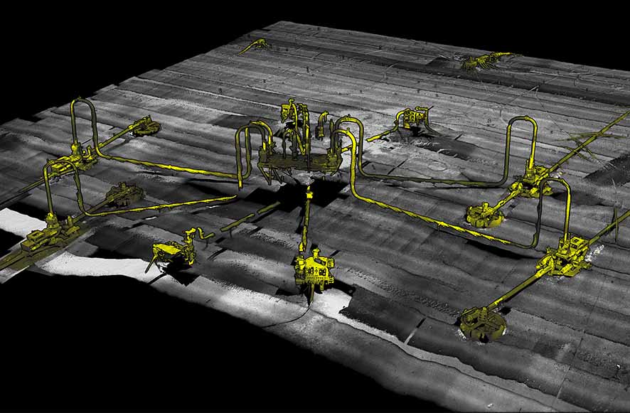
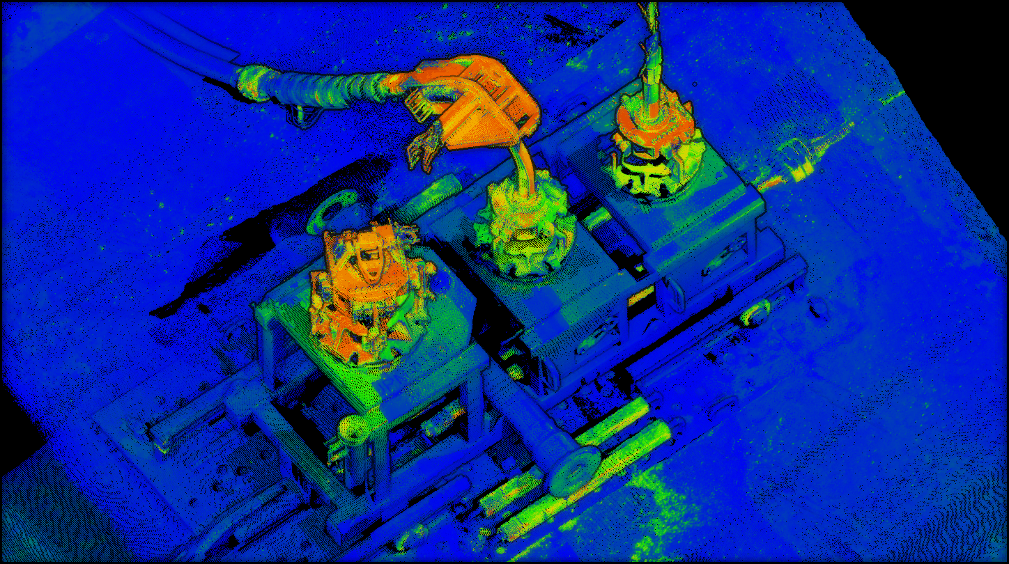
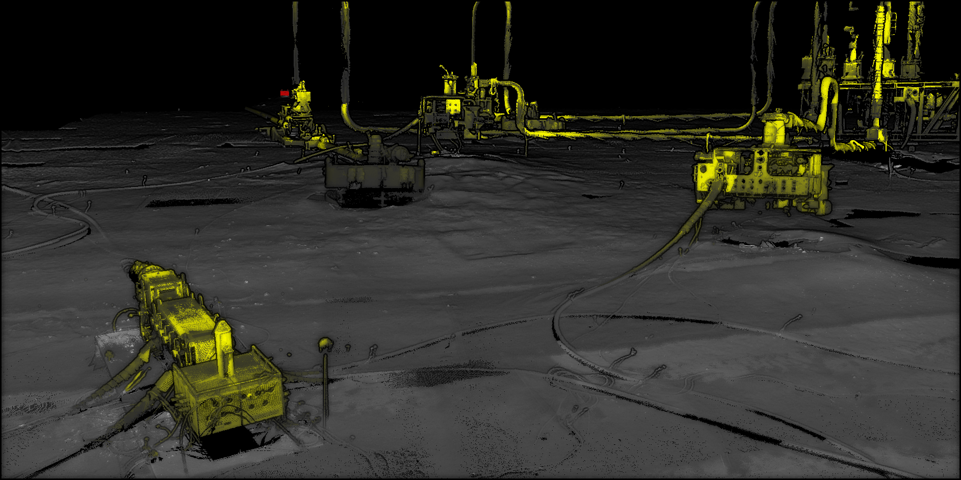
By adopting a dynamic platform, such as an ROV navigated fitted with our SPRINT INS, Syrinx DVL and Fusion 6G (sixth generation) LBL acoustics, a site can be mapped much quicker with much less issues from reduced visibility as the ROV does not have to come into contact with the seabed at the survey site and can move to scan any target of interest. For metrology operations, the ability to dynamically position a laser in close proximity to the structures allows operations to be conducted in reduced visibility, reducing delays, and allowing a greater point density over targets. High resolution point cloud data can contain a wealth of information which can be utilised for various applications.
Whilst contactless subsea metrology is one of the obvious applications, the ability to generate geo-referenced 3D maps at the centimetric accuracy level supports a wide spread of applications also including; structure mapping, pipeline inspections, mooring chain surveys, inland waterway inspections, scour surveys, seabed coral/ fauna mapping, wreck and drilling mud surveys to name a few.
What makes up the system?
 A typical 3D mobile mapping campaign involves equipping a subsea vehicle – be it ROV, AUV or manned-submersible – with a pre-calibrated SPRINT INS co-located with a Syrinx DVL (or our new combined SPRINT-Nav), ROVNav 6 transceiver, high-precision depth sensor, sound velocity sensor and your choice of high resolution laser/camera, LiDAR or multi-beam.
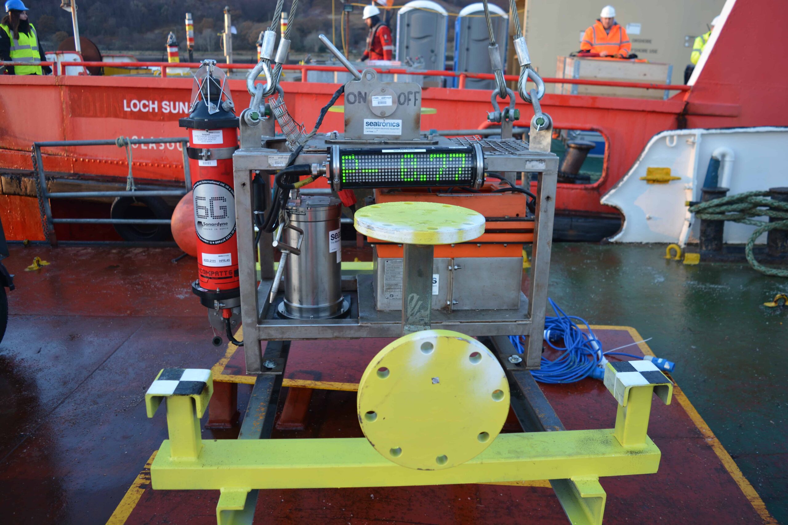
Compatt 6 transponders such as the new Micro model, are deployed on the seabed around the survey area with their approximate relative positions to each other reliably and time efficiently determined by DVL/INS dead reckoning. The vehicle then carries out the required survey of the structure, while the INS, DVL, LBL ranges, depth and sound velocity are gathered by the SPRINT and Fusion software. The process does not require transponder-transponder acoustic line of sight, but can utilise these acoustic baselinemeasurements when available.
On completion of the survey, the raw sensor data is post-processed using our powerful software tool, Janus. Post-processing concurrently calibrates transponder positions using a SLAM (Simultaneous Localisation and Mapping) technique and optimises absolute and relative navigation accuracy. The finished navigation data is then merged with the laser/ camera, LiDAR or multi-beam data to produce a geo-referenced 3D point cloud.
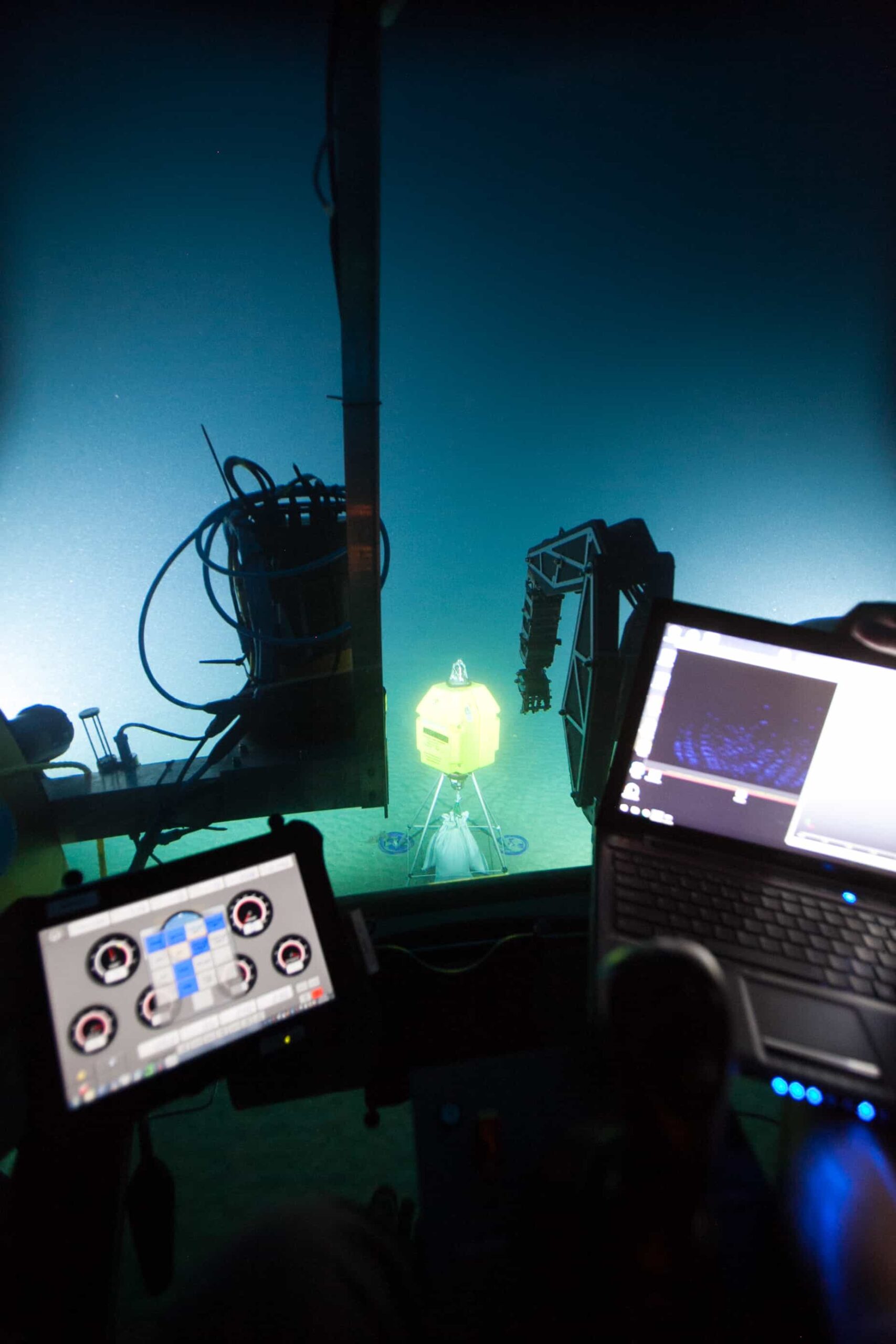
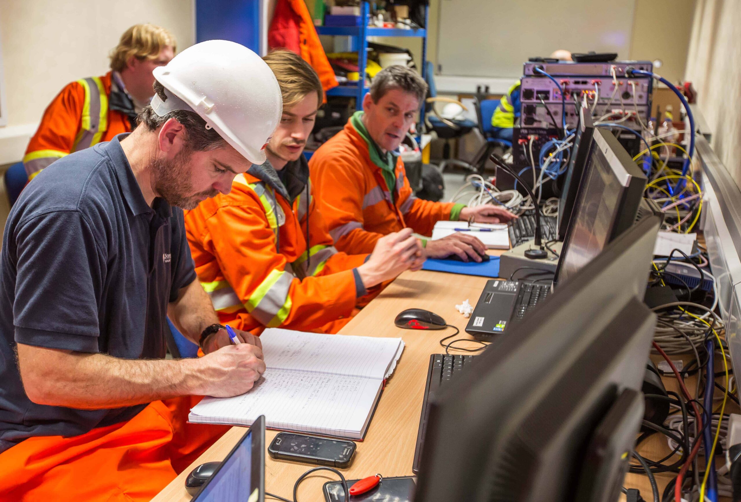 Our factory-supplied equipment is the latest specification and preconfigured to ensure your operation can be mobilised as quickly as possible. In the planning phase of a project, the expert knowledge of our Survey Support Group (SSG) is available to help you plan every aspect of the operation including reviewing procedures and tasks to identify and reduce risk ahead of mobilisation. Highly experienced Sonardyne personnel will then join your offshore survey team to operate the acoustic and inertial system, gather the required navigation data and post-process it offline.
Here’s some of the technical benefits of SPRINT-Mapper for dynamic mobile mapping.
• The ability to aid SPRINT with tightly coupled Fusion 6G two-way travel times, with each range received individually
• The ability to combine individual Syrinx DVL beam velocities rather than generic DVL instrument frame velocity and thereby operate robustly over structures and where DVL beam slant ranges dramatically differ.
• All 6G acoustic aiding (LBL and DVL) uses rich proprietary quality metrics, and timing is guaranteed to the micro-second level.
• System architecture has been designed to remove the risk of issues with latency or timing jitter on ROV MUX communications to topside, which could affect time synchronisation between instruments when receiving 1PPS from topside, as per established methods.
• Janus post-processing software is an extremely powerful tool for ensuring the very highest quality post-processed navigation with full QC of data. It performs forwards and backwards post-processing of the INS data and utilises a host of other proprietary techniques to optimise system performance in every operational scenario and condition.
So what performance can you expect to see? Well, our approach delivers the following 3D point cloud tolerances;
• 1cm level typical accuracy (vertical and horizontal baseline RMS) for single run-line distances of ~20m (typical metrology) and not much worse over longer distances.
• 5-10 cm level typical area (e.g. 50-200m square) mapping accuracy when merging multiple run-lines at arbitrary headings.
Track record
For the past three years, we’ve been working behind the scenes supporting clients with their mobile mapping projects, witnessing firsthand how this game-changing capability can re-write the operational rule book.
MBARI Deep water ROV mobile mapping trials were first performed in 2014 and then again in November 2015 onboard the R/V Western Flyer through co-operation with the Monterey Bay Aquarium Research Institute (MBARI). A conventional Compatt 6G array was deployed and calibrated to act as reference for the mobile mapping trials. The reference acoustic baselines were compared to the 3D point cloud derived baselines. The difference ‘C-O’ RMS between the baselines was just over 3cm with a single baseline error marginally above 5cm. Additionally, simulated flange/hub assemblies were mapped and demonstrated angular accuracy robustly below 0.5 degrees. Baseline Issue15 has the full article.
UTEC/McDermott Following these successful trials, Sonardyne and laser manufacturer 2G Robotics were invited to perform a contactless dynamic metrology trial by UTEC and McDermott in a deep-water operational environment. The operational elapsed time and results were compared to a static laser metrology and delivered on the requirements of meeting typical metrology tolerances whilst delivering operational efficiency and cost savings.
Further operational projects followed in collaboration with 2G Robotics last year, including with DeepOcean and with the National Oceanographic and Atmospheric Administration (NOAA).
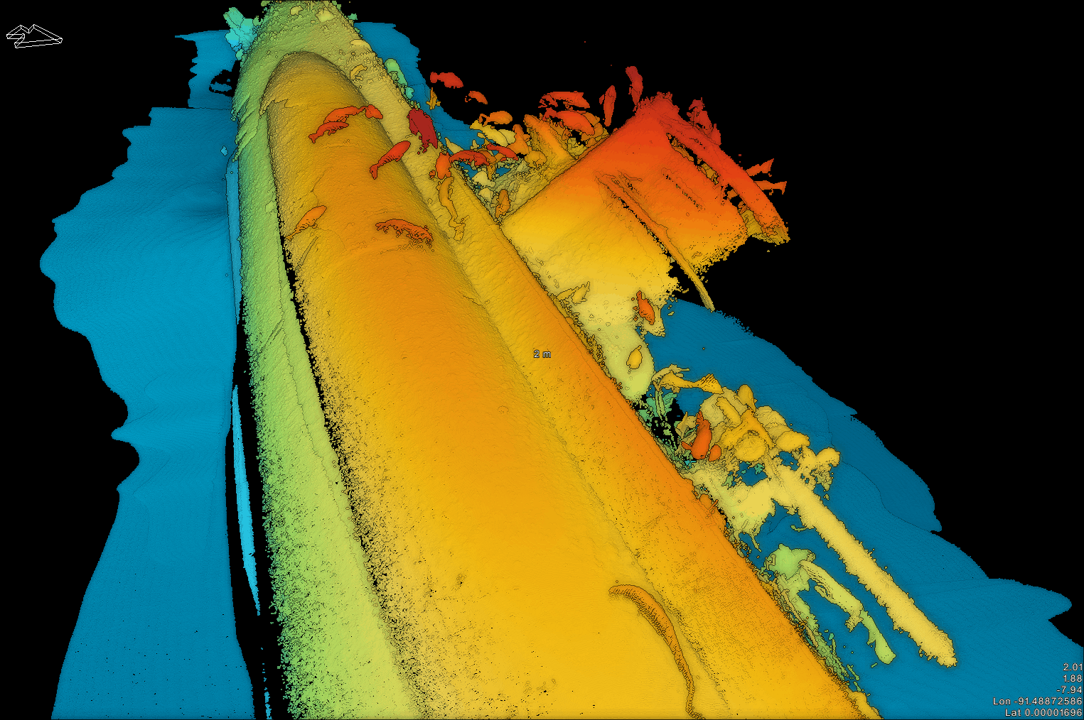 NOAA The project with NOAA demonstrated the versatility of the system; in this case it was installed and operated on a manned submersible to map two key archaeological wreck sites, the U-576 submarine and the freighter SS Bluefields. Even in challenging dynamic and environmental conditions, SPRINT-Mapper provided outstanding accuracy, with the condition of both wrecks, their fittings and features easily distinguished and identifiable for analysis.
DeepOcean DeepOcean’s dynamic survey operation covered 12 drill centre locations and a total of 27 metrologies, setting new bench marks for high resolution contextual3Dsurveywhile proving an alternative and rapid ‘contactless’ solution to conventional metrology surveys.
DOF Late last year, we supported DOF at The Underwater Centre in Fort William, Scotland, to demonstrate mobile mapping to invited industry representatives. The ‘truth’ reference for this trial was traditional Sonardyne 6G LBL acoustic metrologies and third-party gyro packages.
Laser results were an average of inferred metrology from two runs (in same direction). Despite the extreme weather conditions, our full program results are within metrology tolerance of the truth reference.
Tested. Trialled. Proven
 The benefits of underwater mobile mapping have now been proven with ultra-fast wide area surveying, inspection and metrology. Turbidity affecting visibility can be reduced by moving the dynamic vehicle closer to the target. The use of tightly coupled Sonardyne 6G acoustics provides trusted quality control alongside optimal aiding to the INS. Mobile mapping does require a complex system integration of INS, DVL, acoustic ranges and mapping sensor to achieve centimetric results. But this is overcome with our unique, ‘under-one-roof’ capability.
We have ability to merge and post-process all sensors at the raw data level. We have a deep understanding of subsea operations and your commercial pressure. And we have experienced offshore personnel ready to support you every step of the way, de-risking your projects. This proven capability has the potential to revolutionise many subsea operations. Contact us to discuss how it could revolutionise yours.