High-accuracy, long-endurance underwater instrumentation from Sonardyne Inc. is set to play a major role in helping scientists across the US better understand and possibly predict earthquake and tsunami risk at a far greater scale than has been possible before.
Scripps Institution of Oceanography, through a US$5.5 million grant from the US National Science Foundation (NSF), is procuring equipment to be used by the broader scientific community to study seafloor deformation. Comprising of more than 50 Sonardyne Fetch subsea sensor logging nodes, this major new equipment pool will also include Sonardyne’s advanced acoustic positioning modules fitted to three Liquid Robotics Wave Gliders.
These will, for the first time, make highly precise seabed monitoring capability – at scale – available to the entire US earth science community using a technique known as GNSS-A.
GNSS-A combines GNSS-derived surface platform positions with acoustic ranging to seafloor sensors, enabling scientists to make centimetre-level and globally referenced measurements of movement across geological features such as subduction zones, which can cause potentially catastrophic earthquakes and tsunamis.
Unlike on land where these observations are easily acquired using the GNSS network, this level and type of measurement has been either too costly or too impractical to acquire subsea. This has resulted in there being almost no seabed geodetic information, which has limited understanding of the geological mechanisms at work.
“This lack of seabed geodetic data has been a real challenge for scientists,” says Geraint West, Global Business Manager Oceanographic, at Sonardyne. “With access to Wave Gliders, to make the highly accurate measurements to our Fetch sensors, the ability to link subsea measurements within a global reference frame is now practical and affordable. What’s more, we’re able to do this over long periods of time, taking the detailed measurements that are needed over decadal timescales.”
[blockquote author=”David Chadwell, Research Geophysicist at the Marine Physics Laboratory at Scripps”]”Seafloor geodesy is poised to be transformative. It will allow for a broad community of existing and next-generation earth scientists to study active deformation on the seafloor. Improved access to these instruments will foster and communicate knowledge of the new methods and science outside of the current and very small marine community, to a much larger scientific community primarily consisting of highly-skilled land-based geodesists, and an inclusive next-generation scientific workforce.”[/blockquote]
“To date only one prototype vehicle and approximately a dozen seafloor transponders have been available for the scientific community,” says David Chadwell, Research Geophysicist at the Marine Physics Laboratory at Scripps. “This project will add 51 additional seafloor instruments together with three new robotic platforms for making the required measurements. This will approximately quintuple the equipment available to the research community to make these important measurements.
“Seafloor geodesy is poised to be transformative. It will allow for a broad community of existing and next-generation earth scientists to study active deformation on the seafloor. Improved access to these instruments will foster and communicate knowledge of the new methods and science outside of the current and very small marine community, to a much larger scientific community primarily consisting of highly-skilled land-based geodesists, and an inclusive next-generation scientific workforce.”
Stephen Auld – Global Business Manager – Subsea Asset Monitoring
As I discussed in my previous blog, while operators do take care to prevent leaks from occurring, they can and do happen. When they do, they reach the public domain with the understandable and expected negative response and the resulting financial consequences on the companies involved.
Early identification and location of a leak can mitigate the impact. But, depending on the type of asset that needs monitoring or where a seep or leak is thought to be, very different approaches may need to be taken to ensure a timely intervention.
Previously, I identified two types of asset, each of which requires a different monitoring strategy. The first strategy, which I have already covered in detail here, is for specific assets, such as wellheads and their associated structures, which are contained within a limited area. For these, continuous, static, 360 degree monitoring, using our Sentry IMS, provides an automated, near real-time early warning system for any integrity breaches. Continuous monitoring could be employed throughout field life or during a specific phase, such as drilling, as you can read more about here.
Wide area coverage
 The second type of asset, which I’ll cover in this article, is for wider seabed areas, where hydrocarbon or CO2 seepage can occur anywhere within the wider field development. This could be naturally or from an inability to control the reservoir or overburden pressure, or where monitoring is required at emergent underwater carbon capture and storage (CCS) sites. It could also be where subsea infrastructure is more widely distributed, such as along pipeline corridors.
Where natural seepage or leaks occur at an unknown location across widely spread infrastructure, mobile monitoring is the preferred, if not the only, solution. Critical to this strategy, however, is the ability to cover wide areas and gather high resolution data efficiently. This means a need for low power but high resolution imaging systems, compatible with and capable of automated leak detection and reporting.
Solstice – multi-aperture sonar
That’s where our Solstice multi-aperture sonar (MAS) comes in. It’s low power, using just 18 Watts, but packs a punch, covering an impressive 200 m wide swath with an unrivalled 0.15° along-track resolution. Combined, these attributes make Solstice ideal for use on low power, long-endurance autonomous underwater vehicles (AUV) and where area coverage rate (ACR) and low false detection rates are key.
Quite simply, Solstice can map more – and more accurately. This is because it uses a back-projection beamforming technique to focus at every single pixel in the image, as well as accounting for platform motion to produced amazing undistorted imagery with real-time array calibration. With more accurate data, you improve the probability of positive detections using carefully designed and tested on board computer aided detection and classification (CAD/CAC) and automatic target recognition (ATR) algorithms. Better detections mean you get the results you need faster. This is why Solstice is a popular tool in mine hunting operations – where time is critical.
Real-time dynamic underwater leak detection
 For both leak detection and mine hunting applications, the ATR algorithms ‘score’ detections or regions of interest and then save small ‘snippets’ of metadata along with the sonar image data. During the AUV mission these snippets can be automatically transmitted to a following USV or conventional vessel or, alternatively, downloaded when the AUV surfaces. From there these snippets can be sent to shore, via satellite for further interpretation. Onshore, an operator can then request the highest scoring leak images, allowing a high confidence of detection while the survey progresses.
What’s more, other sensors can also be fitted to your AUV, such as physical and chemical instruments, which, along with the Solstice and navigation data, can also be processed in real-time to cross-reference and validate any detected anomalies for sending back to shore via satellite.
Pre-emptive or reactive leak location
The data is impressive, the low power budget is impressive – and it all comes in a just 682 mm-long, 95 mm deep, 760 g (2.11 kg in air) package. This provides options. On a long endurance AUV, the low power consumption enables significant areas to be covered over extended time periods. On a smaller AUV, its small footprint means you can also quickly mobilise a detection capability capable of covering a large area in a small period of time. So you can both have a persistent monitoring presence in your field or quickly and cost-effectively deploy a leak detection asset to a problem area to locate an integrity breach.
Methane and CO2 subsea seep detection
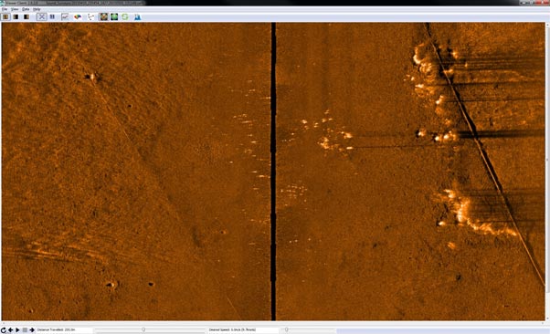
 Solstice is proven. It’s already been used on a number of projects detecting both simulated CO2 leaks in the North Sea and natural methane seeps. During a methane seep detection project we were tasked with detecting naturally occurring seeps from the ocean floor offshore California. As shown in the image above (at 200 m swath), side scan data collected from a Solstice mounted on a Bluefin AUV, the shape and height of the methane plumes close to a pipeline are clear as indicated by the numerous horizontal dark shadows crossing the diagonal pipeline on the starboard channel. Some of the seeps can also be seen to be emanating from pockmarks further away from the pipeline, i.e. closer to the AUV centreline.
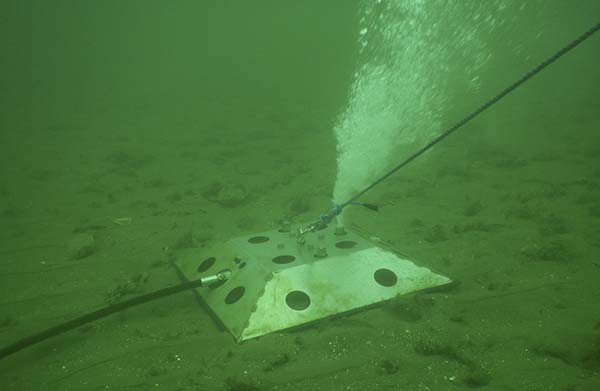
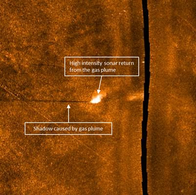
In another project, Solstice’s ability to detect CO2 leaks was put to the test. A test target emitting 15 litres of carbon dioxide a minute was placed on the seafloor for the trial. Our Solstice imagery clearly shows the plume rising up from the seabed by the shadow it casts caused by the obstruction it makes in sonar data return. You can read more about that project here.
Solstice
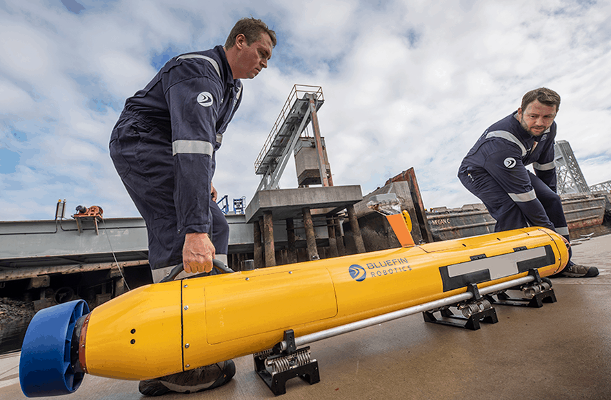
Image Courtesy of General Dynamics
Solstice is also regularly used in other AUV-based seabed search and mapping operations, such as mine detection. In fact, Solstice comes as standard on General Dynamic’s Bluefin-12 and Bluefin-9 AUVs. And, onboard the Bluefin-9, it’s the most powerful sensor package for a two-man portable AUV.
Solstice offers data quality and resolution like no other side scan sonar of the similar size, weight and power. This means you can respond faster, cover more of your assets for less, long term, and with high confidence in the results.
For oil majors’ who have environmental awareness and hydrocarbon containment firmly in their sights for 2025, these are tools that can realise that vision today. Automated monitoring with Solstice is here, proven and available.
All USBL systems calculate position by measuring the range and bearing from a vessel-mounted transceiver to an acoustic transponder fitted to a moving target or placed on the seabed.
Here we offer five top tips on how to get the best out of your USBL systems and make sure your tracking performance in shallow water is trouble free. You can also watch our quick video, below.
Top tip #1
Consider where to deploy your transceiver. Is it on a rigid pole? Mounting your transceiver on a rigid pole will improve the performance of your system in any depth of water, not just shallow water.
Top tip #2
 Make sure there’s enough distance between your vessel hull and your transceiver. This will reduce the amount of background noise from your vessel that interferes with your USBL positioning. Also, consider where on your vessel to put your transceiver. Try to avoid deploying it near the propeller because the noise and aeration from it will affect system performance.
Micro-Ranger 2 is already optimised for shallow water tracking. However, if you’re tracking with Mini-Ranger 2 at an elevation angle above 30 degrees, make sure you have depth aiding turned on at the beacon you’re tracking. This is easy to do. Just go to the beacon table in your Micro-Ranger 2 software, click on the sensor tab and then select the sensor from the depth aiding drop down. It’s also important to turn off depth aiding when you’re tracking underneath the vessel.
Top tip #3
Shallow water environments are by their very nature highly variable. Consider the environment you’re working in and pick the system setting that suits it best in order to optimise performance. For example, if you’re working in a noisy environment, such as waves or rain, you might want to set your beacon power levels to high. This will aid the acoustics to cut through that background noise and make sure they’re detected.
If you’re working in very calm water or near structures or walls of docks, for example, this may result in echoes and reverberation. In this environment, it’s best to set your power levels to ultra-low. This will avoid the echoes giving you false detections, so you’ll get much more accurate tracking. You can change a beacon power by opening the beacons table, then clicking on the advanced settings tab and selecting the power level you want from the drop down menu.
Top tip #4
If you’re always tracking a target at the stern of your vessel at high elevation, such as a tow fish, you might want to tilt your transceiver head towards your target. This will increase sensitivity in that direction and improve performance. However, seek advice because if this is implemented poorly it may result in increased background noise and reverberation. You can also use a 30 degree adaptor flange to point the transceiver back to the target.
Remember, Micro-Ranger 2 is already optimised for shallow water tracking, so tilting the head is not required. And, as we outlined in tip #1, care should be taken on the position of the transceiver to make sure you don’t introduce any more internal noise into the system. Also, if you tilt the transceiver head, remember to turn the depth aiding off.
Top tip #5
The type of beacon you use can be critical. Omni-directional beacons are used extensively in shallow water tracking and their performance can be optimised in the way we’ve described above. However, sometimes a directional beacon may be your best option, especially in high elevation high noise acoustic environments. These beacons focus their acoustic energy to make them much more detectable, giving you more robust tracking in those situations.
We hope these tips have been useful. If you have any questions, please don’t hesitate to get in touch. We’re here to help you get the best out of your Sonardyne USBL system.